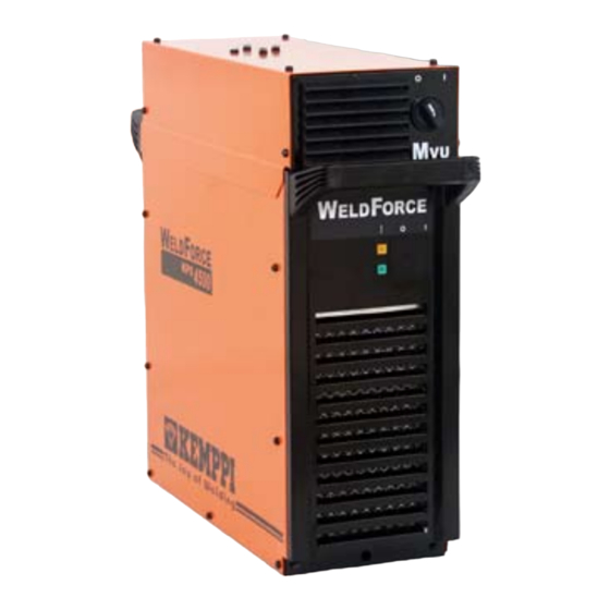
Kemppi WeldForce KPS 3500 Service Manual
Hide thumbs
Also See for WeldForce KPS 3500:
- Operation instructions manual (13 pages) ,
- Operation instructions manual (13 pages)
Table of Contents
Advertisement
Advertisement
Table of Contents

Summary of Contents for Kemppi WeldForce KPS 3500
- Page 1 Service manual Ver. 1.0...
-
Page 2: Table Of Contents
Control cable connectors………………………………...9 Troubleshooting diagram…..……………………….10 Control card A001 layout….…………………...………..11 Control card A001 jumper….....……………...11-12 Control card A001 leds….………….……………………12 IGBT gate pulse…...……………………………………...13 Voltage over the lower IGBT………….……………..14 Voltage after the secondary diode cards….…………..15 Cooling unit control…….....………………………...16 Structure (Kemppi WELDFORCE 4500)……………..17 Notes……………………………………………....18... -
Page 3: Technical Data
Technical data KPS 3500 KPS 4500 KPS 5500 Supply voltage 3~50/60 Hz 400 V –15…+20 % 400 V –15…+20 % 400 V –15…+20 % Loadability (+ 40° C) 60 % ED 450 A (21,5 kVA) 550 A (28 kVA) 80 % ED 350 A (15 kVA) 420 A (20 kVA) 500 A (24,5 kVA) -
Page 4: Operation Principle
Operation principle KEMPPI WELDFORCE -power sources are versatile, MIG/MAG- and MMA-suitable inverters. KEMPPI WELDFORCE -power sources are based on IGBT technology and controlled by PWM principle. The inverter frequency changes by the load, in range of 14 - 24 kHz. -
Page 5: Simplified Main Circuit Diagram
Simplified main circuit diagram Control card A001 Main circuit components Varistors (550V) Filter card Z004 Main switch S001 The filter card Z004 dampens the electromagnetic disturbances conducting to the net (EMI). Varistors (550 V) form an overvoltage protection against low energy voltage spikes. Note! Filter card Z004 and varistors are mounted before the main switch S001! - Page 6 2 x 25 µ F/ 700 VDC Discharge resistors Work capacitors 3500: 18 x 0,15 µ F/ 1000 VDC 4500: 22 x 0,15 µ F/ 1000 VDC IGBT-module 3500: 100 A/ 1200 V RC-protection 4500: 150 A/ 1200 V (KEMPPI WELDFORCE 3500and 4500)
- Page 7 4 x 33 k Ω / 2 W IGBT-modules 2 x 200 A/ 1200 V (KEMPPI WELDFORCE 5500) Inverter´s main parts are the workcapacitors, IGBT-transistors and the main transformer T001. Inverter´s power adjustment is based on pulse width modulation (PWM). RC-protections ease the stress on the semiconductors.
- Page 8 Main circuit components Secondary choke and shunt resistor Shunt amplifier OCV smoothing circuit Diode cards The main transformer T001 secondary voltages are full-wave rectified by the diode cards. The secondary voltage waves are dampened by secondary choke L002. The secondary circuit current is measured by a shunt resistor.
-
Page 9: Control Cable Connectors
The cooling unit KWU-10 is connected to connectors X010 and X011. KPS 4500 KPS 5500 The control card A001 is similar in all Kemppi WELDFORCE -power sources. The machine size is coded with short circuit loops, except in Kemppi WELDFORCE 3500, which has no short circuit loops. -
Page 10: Troubleshooting Diagram
Troubleshooting The machine may only be repaired by a technician or a workshop licensed and authorized to do the job! First do a visual check to find any possible loose connectors, broken wires or signs of overheating. Troubleshooting diagram PROBLEM POSSIBLE CAUSE REMEDY The power source will not start. -
Page 11: Control Card A001 Layout
Control card A001 layout 5 6 7 R164 R164 Inverter frequency Control card A001 jumper functions Factory setting MIG, wire feeder is other MIG, wire feeder is KWF than KWF Scratch-TIG enabled Scratch-TIG disabled OCV approx.. + 16 V OCV is approx. + 65 V (VRD) Not in use Factory setting... -
Page 12: Control Card A001 Leds
Control card A001 jumper functions Recalls the EEPROM parameter´s factory Factory setting settings. Flash-memory update in malfunction situations Factory setting. Enables the flas-memory programming in production. Must remain closed! Factory setting. Flash-memory block 2 in use. Flash-memory block 1 in use. Control card A001 LEDs H1 LED: FANS, LED is on, when fans aren´t rotating and vice versa. -
Page 13: Igbt Gate Pulse
IGBT gate pulse Control cardi A001 The gate pulse on values 10A/14,5V (MIG), meas. point a 10V, 20µs/DIV The gate pulse on values 450A/36,5V (MIG), meas. point a 10V, 20µs/DIV... -
Page 14: Voltage Over The Lower Igbt
Voltage over the lower IGBT Voltage over the lower IGBT on values 10A/14,5V (MIG), meas. point b 100V, 20µs/DIV Voltage over the lower IGBT on values 450A/36,5V (MIG), meas. point b 100V, 20µs/DIV... -
Page 15: Voltage After The Secondary Diode Cards
Voltage after the secondary diode cards Voltage after the secondary diode cards on values 10A/14,5V (MIG), measuring point c 20V, 20µs/DIV Voltage after the diode cards on values 450A/36,5V (MIG), measuring point c 20V, 20µs/DIV... -
Page 16: Cooling Unit Control
Cooling unit control 400 V ∼ 400 V ∼ + 24 V Pump control Monitoring (pressure / temperature) Voltage on connector X010 between pins 2-6, measuring point d: a) Pump motor ON b) Pump motor OFF c) Pump motor continous run selected Voltage on connector X010 between pins 1-6, measuring point e: a) Pump motor is ON, monitoring OK b) Coolant has overheated >... -
Page 17: Structure
IGBT VG102 Primary rectifier VG101 Diodes VG103/VG104 Rectifier unit VG105 Main circuitcardZ001 Smoothing capacitors Working capacitors Filter card Z004 Main switch S001 Filter card Z003 Commutation unit L003 Current transformer LT301 Chokes LL301/LL302 KWU connections Primary choke L001 (KEMPPI WELDFORCE 4500) -
Page 18: Notes
Notes...


Need help?
Do you have a question about the WeldForce KPS 3500 and is the answer not in the manual?
Questions and answers