Table of Contents
Advertisement
Quick Links
Advertisement
Table of Contents

Subscribe to Our Youtube Channel
Related Manuals for BETCO STEALTH ASC24BT


Summary of Contents for BETCO STEALTH ASC24BT
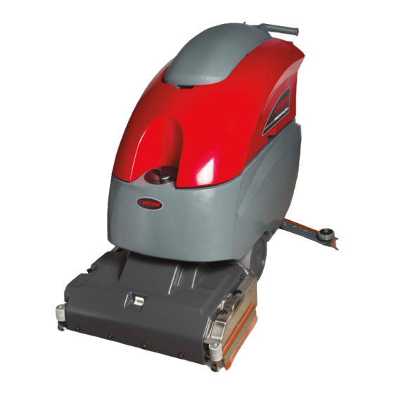
- Page 1 E29951-00 E29952-00 STEALTH ASC24BT 24" Cylindrical Scrubber ™ with Traction Drive Operator and Parts Manual 1001 Brown Avenue • Toledo, Ohio 43607-0127 Customer Service: 888-GO-BETCO • Fax: 800-445-5056 • Technical Service: 877-856-5954 • www.betco.com...
-
Page 2: Table Of Contents
TABLE OF CONTENTS RECEIVING THE MACHINE..........3 TECHNICAL SPECIFICATIONS ........4 GENERAL SAFETY REGULATIONS ......... 5 MACHINE PREPARATION ........6 - 12 OPERATION ............13 - 14 TURNING OFF THE MACHINE ........15 DAILY MAINTENANCE ..........16 -17 WEEKLY MAINTENANCE ..........18 TROUBLESHOOTING ........... 19 BRUSH AND SELECTION USE........ -
Page 3: Receiving The Machine
RECEIVING THE MACHINE Immediately check, when receiving the machine, that all the materials indicated on delivery documents have been received and also that the machine has not been damaged in transit. If it has been damaged, this damage must be immediately reported to the shipper and also to our customer’s service department. -
Page 4: Technical Specifications
TECHNICAL DESCRIPTION Measurement Unit Stealth ASC24BT ™ Working Width Inches Work Capacity Sq. Ft. / Hr. 32,000 Brush Width Inches Brush RPM Brush Pressure Lbs. (Kg) 110 (50) Brush Motor V / HP / W 24 / 0.75 / 560 Drive Type Automatic Forward Speed... -
Page 5: General Safety Regulations
• Before using the machine make sure that all doors and covers are positioned as shown in this operating and maintenance manual. • When your BETCO machine is ready to be retired, the machine must be disposed of properly. It contain oils and electronic components. The machine was built using totally recyclable materials. -
Page 6: Machine Preparation
MACHINE PREPARATION 1. HANDLING THE PACKED MACHINE The machine is contained in specific packaging. It is not possible to place more than two packages on top of each other. The total weight is 735 Lbs. (335 kg). The overall dimensions of the package are: A: 69 in (1760 mm) B: 40 in (1020 mm) C: 50 in (1270 mm) - Page 7 Weight 97 lb. (44 kg) WARNING: Your charger must be set according to the type of bat- tery you install. Call BETCO customer service to ensure correct charger setting after replacement batteries are installed. • The batteries must be handled using lifting and transportation means suitable for the weight and dimensions.
- Page 8 MACHINE PREPARATION 5. BATTERY MAINTENANCE For maintenance and recharging, follow the instructions provided by the battery manufacturer. 6. BATTERY DISPOSAL When the battery reaches the end of its life, it must be disconnected by certi- fied professional, then lifted (using the handles and suitable lifting device) to remove it from the battery compartment.
- Page 9 MACHINE PREPARATION 9. CONNECTING THE BATTERY CONNECTOR Connect the battery connector (2) to the machine connector (1) 10. BATTERY INDICATOR The battery indicator uses LEDs and has 8 positions (7 yellow - charged batter- ies, and 1 red - run down batteries). WARNING: A few seconds after the red indicator light comes on, the brush motor turns off automatically.
- Page 10 MACHINE PREPARATION 11. INSTRUMENT PANEL COMPONENTS The instrument panel components are identified as follows: A. Paddles to activate brushes / traction (located beneath the grip) B. ON/OFF key switch C. Battery level / hour meter 12. REAR COMPONENTS The rear components are identified as follows: A.
- Page 11 MACHINE PREPARATION 15. ADJUSTING THE SQUEEGEE HEIGHT The height of the squeegee must be adjusted based on wear of the squeegee. To do this, turn the knob (2) counter clockwise to raise the squeegee, and clock- wise to lower it. Note: the right and left wheels must be adjusted to the same level, so the squeegee works parallel to the floor.
- Page 12 MACHINE PREPARATION 18. SOLUTION TANK Remove the front inlet cap and check the solution filter is correctly installed. Check the solution filter cover (beneath the tank) is correctly closed. 19. SOLUTION TANK • Fill the tank with clean water in the front fill location (1) or at the rear fill location (2) at a temperature not exceeding 120°F (50°C).
-
Page 13: Operation
OPERATION 1. PREPARING TO WORK A. Connect the battery plug (1) to the machine plug B. Turn the key (1) of the main switch to the "ON" position (clockwise). The bat- tery charge level indicator lights will immediately come on. C. - Page 14 OPERATION 2. REVERSE MOVEMENTS To move in the reverse direction, push the switch levers (1) forward. WARNING: When making reverse movements, raise the squeegee. 3. OVERFLOW DEVICE The machine has a float in the filter basket that activates when the recovery tank is full and stops airflow into the vacuum.
-
Page 15: Turning Off The Machine
SHUTTING DOWN THE MACHINE 1. END OF WORK When shutting down the machine and before you perform any type of mainte- nance: A. Turn off the solution control valve using the handle (1) B. Raise the brush deck using the foot lever (2) C. -
Page 16: Daily Maintenance
DAILY MAINTENANCE 1. CLEANING THE RECOVERY TANK A. Raise the vacuum unit (1). B. Remove the drain hose (2) and empty the tank. C. Rinse the inside of the tank with water. D. Close the vacuum unit on the machine and replace the drain hose cap and drain hose. - Page 17 DAILY MAINTENANCE 4. CLEANING THE SQUEEGEE Ensure the squeegee is always clean, to improve drying results. To clean: A. Remove the squeegee vacuum hose from the squeegee shoe adapter. B. Remove the cotter pins that attach the pins of the squeegee shoe. C.
-
Page 18: Weekly Maintenance
WEEKLY MAINTENANCE 1. CLEANING THE SQUEEGEE HOSE Every week, or whenever vacuum seems to be unsatisfactory, check the squee- gee hose for obstructions. To clean: A. Remove the hose from the squeegee shoe adapter on the squeegee shoe. B. Remove the other end from the recovery tank. C. -
Page 19: Troubleshooting
TROUBLESHOOTING GUIDE INSUFFICIENT WATER ON THE PAD 1. Verify that the solution control valve – located beneath the symbol – (1) is turned on. 2. Verify that there is water in the solution tank. THE MACHINE DOES NOT CLEAN WELL 1. -
Page 20: Parts Diagrams And Listings
BRUSH DECK ASSEMBLY DIAGRAM 1.18 1.16 1.12 1.14 1.13 1.10 1.11 1.15 1.17... - Page 21 BRUSH DECK ASSEMBLY PARTS LISTING Item# Part # Description Qty. Item# Part # Description Qty. E83434 Brush Hub E22507 Nut, M6 x 8 E83435 Pin / Shaft E83799 Flat Washer M6.6x18x2 SS E86275 Barbed Elbow, 3/8" E22197 Side Plate E83580 Ring E81944 Grommet...
- Page 22 BRUSH BASE ASSEMBLY DIAGRAM 20.6 20.1 20.2 20.3 20.4 20.5...
- Page 23 BRUSH BASE ASSEMBLY PARTS LISTING Item# Part # Description Qty. Item# Part # Description Qty. E83274 Support E83831 Flat Hd Soc Machine Screw M6x20 SS E22523 Stop E22511 Flat Hd Soc Machine Screw M6x16 E22547 Screw E81778 Spring E82701 Tube E83947 Hex Nut, M6x5 SS E83469...
- Page 24 DECK LIFT ASSEMBLY DIAGRAM...
- Page 25 DECK LIFT ASSEMBLY PARTS LISTING Item# Part # Description Qty. Item# Part # Description Qty. E22289 Hex Bolt M10x50 Zinc E20220 Brush Deck Lift Arm Linkage E22573 Bushing E20112 Hex Nut, M6x6 Zinc E22574 Lever E83852 Hex Nut, M6x5 E22575 Spacer E82808 Hex Jam Nut, M8X5 Zinc...
- Page 26 SQUEEGEE ASSEMBLY DIAGRAM...
- Page 27 SQUEEGEE ASSEMBLY PARTS LISTING Item# Part # Description Qty. Item# Part # Description Qty. E89559 Squeegee Vacuum Adapter (H) E22352 Center Front Squeegee Blade Clamp E82275 Pin, Adjustable Mounting M10 Zinc E22354 Outer Front Squeegee Blade Clamp E22355 Center Rear Squeegee Blade Clamp E82280 Pin, Fixed Mounting M10 Zinc E22351...
- Page 28 SQUEEGEE SUPPORT ASSEMBLY DIAGRAM 3.25 3.30 3.10 3.26 3.32 3.16 3.11 3.15 3.22 3.18 3.31 3.12 3.14 3.29 3.21 3.23 3.26 3.34 3.28 3.19 3.23 3.24 3.31 3.17 3.18 3.20 3.33 3.27 3.35 3.27 3.33 3.13...
- Page 29 SQUEEGEE SUPPORT ASSEMBLY PARTS LISTING Item# Part # Description Qty. Item# Part # Description Qty. 3.26 E20121 Flat Washer M5x15x1.5 Zinc E20313 Squeegee Lift Lever E88279 Micro Switch Sealed 3.27 E82761 Flat Washer M6x12x1.6 Zinc E22583 Support 3.28 E83278 Flat Washer M6.5x24x2 Zinc E20010 Pivot Pin 3.29...
- Page 30 FRAME ASSEMBLY DIAGRAM 12.2 12.8 12.10 12.13 12.9 12.3 12.11 12.4 12.12 12.5 12.7 12.8 12.1 12.6...
- Page 31 FRAME ASSEMBLY PARTS LISTING Item# Part # Description Qty. Item# Part # Description Qty. E81917 Bolt, Hex, M8x20, Zinc E82689 Spring, 15x2x60mm Galv Extension E82395 Washer E22592 Screw, M6 x 35 E22584 Spacer E20390 Soc Hd Cap Screw M8x22 Zinc E20609 Bearing Mount Base E20111...
- Page 32 TANK ASSEMBLY DIAGRAM 19.8 19.9 19.7 19.6 19.4 19.2 19.4 19.1 19.3 19.5 19.1...
- Page 33 TANK ASSEMBLY PARTS LISTING Item# Part # Description Qty. Item# Part # Description Qty. E82808 Hex Jam Nut, M8X5 Zinc E20107 Screw, Pan Hd Phil Self Tap M4.2x16 SS E20432 Hose Clamp E20127 Flat Washer M9x18x1.5 Zinc E81619 Cable Tie Holder E85762 Hose Clamp E20468...
- Page 34 VACUUM LID ASSEMBLY DIAGRAM 2.24 2.11 2.13 2.14 2.18 2.17 2.15 2.10 2.16 2.25 2.23 2.30 2.12 2.19 2.26 2.28 2.21.2 2.21.1 2.22 2.21 2.21.3 2.21.4.2 2.21.4 2.21.4.1...
- Page 35 VACUUM LID ASSEMBLY PARTS LISTING Item# Part # Description Qty. Item# Part # Description Qty. 2.17 E20182 Sound Deadening Foam E20265 Plate E20305 Mounting Ring 2.18 E22519 Gasket E20652 Sound Deadening Foam 2.19 E22075 Hook, Vac Lid Bale E20180 Sound Deadening Foam 2.21 E88291 Vacuum Motor 24VDC 310W...
- Page 36 SOLUTION ASSEMBLY DIAGRAM...
- Page 37 SOLUTION ASSEMBLY PARTS LISTING Item# Part # Description Qty. Item# Part # Description Qty. E82322 Solenoid Valve, 24v 10w 3-Port Nylon E20004 Tubing 12 ID x 200 L E81348 Hose E83858 Oval Hd SL Machine Screw M4x12 SS E82693 Hose, 17 OD x 12 ID x L 420 E83617 O-Ring, 14x2.5mm Buna-N E22612...
- Page 38 HANDLEBAR ASSEMBLY DIAGRAM 3.15 3.10 3.13 3.17 3.16 3.14 3.12 3.17 3.11...
- Page 39 HANDLEBAR ASSEMBLY PARTS LISTING Item# Part # Description Qty. Item# Part # Description Qty. E22615 E82351 Key Switch Assembly w/Keys E83173 Contact, Key Switch E83836 Hex Bolt M5x16 Zinc E83316 Key Switch E20288 Soc Hd Cap Screw M8x30 Zinc E83316 Key Switch E20242 Pan Hd Phil Machine Screw M3x20 Zinc...
- Page 40 ELECTRICAL CONTROL ASSEMBLY DIAGRAM...
- Page 41 ELECTRICAL CONTROL ASSEMBLY PARTS LISTING Item# Part # Description Qty. Item# Part # Description Qty. E22194 Mounting Plate E20484 Fuse Block E20536 Buss Bar E83170 Fuse, 80 Amp E20448 Bracket E83628 Remote control switch E20097 Hex Bolt M8x40 SS E20129 E20248 Hex Nut, M4x4 Zinc E20468...
- Page 42 ELECTRICAL DIAGRAM...
- Page 43 ELECTRICAL LISTING Item# Part # Description Item# Part # Description E82569 Variable Speed Controller E82351 Key Switch Assembly w/Keys E88293 Battery Check Card, Hour Meter E83952 Circuit Breaker 30A E11410 SB175 Red Electrical Connector ET1002 Part Placeholder for Fimap Parts - FI1241 E11410 SB175 Red Electrical Connector E88249...
- Page 44 ELECTRICAL DIAGRAM...
-
Page 45: Battery Check Card - Hour Meter
BATTERY CHECK CARD – HOUR METER 1. Verify that when turning on the machine the battery check card has the following starting sequence: • Turning on of the LED which correspond to the set-up (red LED = “0”). • Turning on of all the LEDs (check of the lamps) •... -
Page 46: Brake Adjustment
BRAKE ADJUSTMENT 1. Adjust the brake pads on the wheels to lock the wheels when the brake lever reaches the third ratchet notch. 2. To adjust the pads: • Unscrew the M8 jam nut. • Adjust the pad. • Tighten the M8 jam nut. VACUUM SYSTEM INSPECTION 1. -
Page 47: Squeegee Adjustment
SQUEEGEE ADJUSTMENT 1. Adjust the inclination adjuster of the squeegee assembly until the squeegee blade has a uniform deflection along its entire length. 2. Adjust the height of the squeegee wheels using the knob such that the squee- gee blade has an inclination between 30 and 45 degrees. 3. -
Page 48: Check List
CHECK LIST Functional check of the machine Check the functionality of switches and warning lamps. Check the functionality of the switch lever. Check the functionality of the brush deck. Check the functionality of the brush motor. Check the functionality of the solenoid valve. Check the functionality of the vacuum motor. -
Page 49: Maintenance Schedule
MAINTENANCE SCHEDULE RECOMMENDED SERVICE INTERVALS Stealth ASC24BT ™ (HOURS) 750 1,000 Machine components Suggested replacement DAILY BATTERIES Check water level and add if necessary DAILY Check cleanless of machine battery tray ELECTRIC Check state of power contactors and fuses Check state of electric cables crossing the machine SOLUTION TANK Check cleanless of solution filter... -
Page 50: Wear Items
WEAR ITEMS Stealth™ ASC24BT PART NUMBER DESCRIPTION E22512 Brush, General Purpose, 0.4mm E22516 Brush, Medium Duty, 0.6mm E22517 Brush, Tynex Grit, 0.9mm E22503 Side Squeegee, 30 SH Gum Rubber E22513 Side Squeegee, 40 SH Gum Rubber E88953 Squeegee Blade Kit, 42.75" E22264 Squeegee Blade Kit Poly, 42.75"... -
Page 52: Warranty
Service Distributor. If the original part is returned within the warranty policy period from date of delivery for inspection by Betco and is found to be defective the owner will be credited for the cost of replacement parts plus shipping and handling.
Need help?
Do you have a question about the STEALTH ASC24BT and is the answer not in the manual?
Questions and answers