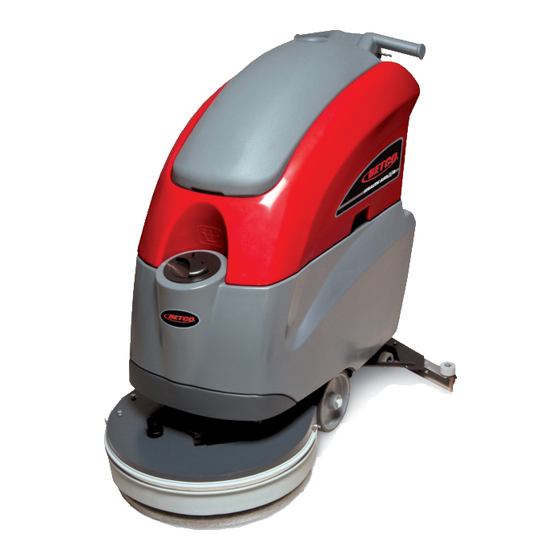
BETCO STEALTH ASD20B Operator And Parts Manual
20” automatic scrubber with brush assist
Hide thumbs
Also See for STEALTH ASD20B:
- Operator and parts manual (64 pages) ,
- Operator and parts manual (48 pages) ,
- Operator and parts manual (52 pages)
Table of Contents
Advertisement
Quick Links
Advertisement
Table of Contents

Related Manuals for BETCO STEALTH ASD20B


Summary of Contents for BETCO STEALTH ASD20B
- Page 1 E87030-00 E88062-00 20” Automatic Scrubber ™ STEALTH STEALTH ASD20B ASD20B with Brush Assist Operator and Parts Manual 1001 Brown Avenue • Toledo, Ohio 43607-0127 Customer Service: 888-GO-BETCO • Fax: 800-445-5056 • Technical Service: 877-856-5954 • www.betco.com...
-
Page 2: Receiving The Machine
RECEIVING THE MACHINE SERIAL # PLATE Immediately check, when receiving the machine, that all the materials indicated on delivery documents have been received and also that the machine has not been damaged in transit. If it has been damaged, this damage must be immediately reported to the shipper and also to our customer’s service department. - Page 3 TECHNICAL DESCRIPTION Rated power HP (W) 1.3 (950) Working width In (mm) 19.7 (500) Rear squeegee width In (mm) 29.2 (742) Work capacity /h (m 15,600 (1450) Water consumption Brush & Pad (diameter) ∅ in (mm) 19.7 (500) Brush RPM Brush pressure lb (Kg) 51 (23)
-
Page 4: Symbols Used On The Machine
SYMBOLS USED ON THE MACHINE Solution valve symbol Used to indicate the water regulation switch Brush release symbol Used to indicate the button for automatic brush release Battery charge gauge Battery symbol Open book symbol Used to tell the operator to read the manual before using the machine Maximum solution temperature gauge Located near the solution tank inlet... -
Page 5: General Safety Regulations
Dispose of consumables in accordance with existing laws and codes. When your BETCO machine is ready to be retired its entire component materials must be disposed of properly. They contain oils and electronic components. The machine itself was built using totally recyclable materials. -
Page 6: Machine Preparation
MACHINE PREPARATION 1. HANDLING THE PACKED MACHINE The machine is contained in specific packaging. It is not possible to place more than two packages on top of each other. The total weight is 220 lb (100kg). The overall dimensions of the package are: 45.1 in (1145mm) 26.2 in (665mm) 48.4 in (1230mm) -
Page 7: Battery Installation
Weight 68 lb (31kg) WARNING: Your charger must be set according to the type of battery you install. Call BETCO customer service to ensure correct charger setting after replacement batteries are installed. The batteries must be handled using lifting and transportation means suitable for the weight and dimensions. -
Page 8: Battery Maintenance
MACHINE PREPARATION 5. BATTERY MAINTENANCE For maintenance and recharging, follow the instructions provided by the battery manufacturer. 6. BATTERY DISPOSAL When the battery reaches the end of its working life, it must be disconnected by certified professional, then lifted (using the handles and suitable lifting device) to remove it from the battery compartment. -
Page 9: Connecting The Battery Connector
MACHINE PREPARATION 9. CONNECTING THE BATTERY CONNECTOR Connect the battery connector (2) to the machine connector (1) 11. BATTERY INDICATOR The battery indicator uses LEDs and has 8 positions (7 yellow - charged batteries, and 1 red - run down batteries). WARNING: a few seconds after the red indicator light comes on, the brush motor switches off automatically. -
Page 10: Instrument Panel Components
MACHINE PREPARATION 12. INSTRUMENT PANEL COMPONENTS The instrument panel components are identified as follows: 1- Paddles to activate brushes / traction (located beneath the grip) 2- ON/OFF key switch 3- battery level / hour-counter display 13. REAR COMPONENTS The rear components are identified as follows: 1- Foot pedal to raise the brushes 2- Water / solution level hose 3- Drainage hose with recovery tank cap... -
Page 11: Adjusting The Squeegee Height
MACHINE PREPARATION 16. ADJUSTING THE SQUEEGEE HEIGHT The height of the squeegee must be adjusted based on wear and tear of the squeegee blade. To do this, turn the knobs (2) counter clockwise to raise the squeegee, and clockwise to lower it. Note: the right and left wheels must be adjusted to the same level, so the squeegee can work parallel to the floor. -
Page 12: Solution Tank
MACHINE PREPARATION 19. SOLUTION TANK Remove the front inlet cap and check the solution filter is correctly fitted. Check the filter cap (beneath the solution tank, at the back) is correctly closed. 20. SOLUTION TANK Fill the tank with clean water in the front fill location (1) at a temperature not exceeding 120°F (50°C). -
Page 13: Assembling The Brush
MACHINE PREPARATION 22. ASSEMBLING THE BRUSH With the base up, insert the brush and position it in line with the plate beneath the base. Lower the base, turn the key (1) to position “1”, push the paddles (2) on the handlebars. -
Page 14: Machine Operation
OPERATION MACHINE OPERATION 1. Connect the battery plug (1) to the machine plug 2. Turn the key (1) of the main switch to the "ON" position (clockwise). The battery charge level indicator lights will immediately come on. 3. Turn on the water valve (2) (the water falls automatically while the brushes are turning). 4. -
Page 15: Forward Movements
OPERATION 3. FORWARD MOVEMENTS The traction of these machines is obtained by means of the pad which, working slightly inclined, is able to drag the machine forwards. To move the machine, you must use the key then activate the paddles levers (1) on the handlebars. WARNING: when making even brief reverse movements, check the squeegee and base are raised. -
Page 16: Shutting Down The Machine
SHUTTING DOWN THE MACHINE 1. AT THE END Proceed as follows when shutting down the machine and before you perform any type of maintenance: 1. Turn off the valve using its handle (1) 2. Raise the brush deck using the pedal (2) 3. -
Page 17: Daily Maintenance
DAILY MAINTENANCE 1. CLEANING THE RECOVERY TANK Raise the vacuum cover (1) and prop it open using the lifting rod on the right-hand side of the lid. Remove the drainage hose (2) from its fitting and empty the tank. Rinse the inside of the tank well with water. Reposition the cover on the machine and replace the drainage hose cap and drainage hose. -
Page 18: Cleaning The Squeegee
DAILY MAINTENANCE 4. CLEANING THE SQUEEGEE Ensure the squeegee is always clean, for better drying results. To clean it you must: 1. Remove the hose from the squeegee 2. Loosen the knobs (1) at the hose nozzle 3. Remove and clean the nozzle 4. -
Page 19: Weekly Maintenance
WEEKLY MAINTENANCE 1. CLEANING THE SQUEEGEE HOSE Every week, or whenever vacuum seems to be unsatisfactory, check the squeegee hose for obstructions. To clean it, proceed as follows: 1. Remove the hose from the sleeve on the squeegee 2. Remove the other end from the recovery tank 3. -
Page 20: Troubleshooting Guide
TROUBLESHOOTING GUIDE INSUFFICIENT WATER ON THE PAD 1. Check the valve – located beneath the symbol – (1) is turned on. 2. Check there is water in the solution tank. THE MACHINE DOES NOT CLEAN WELL 1. Check the state of wear and tear of the pad and, if necessary, replace it. 2. - Page 21 CHOOSING AND USING THE BRUSHES POLYPROPYLENE BRUSH (PPL) Used on all types of floors. Good resistance to wear and tear, and hot water (no greater than 140°F (60°C)). The Polypropylene brush is non-hydroscopic and therefore retains its characteristics even when working in wet conditions. NYLON BRUSH Used on all types of floors.
- Page 23 Item Part Description QTY. Number Number E88272 Brush Deck Splash Guard E20073 Brush Deck E83970 Bushing E83802 Hex Bolt M8x30 Zinc E81709 Nyloc Hex Nut, M8 Zinc E83404 Flat Washer M9x24x2.5 Zinc...
- Page 25 Item Part Description QTY. Number Number E20011 Motor Mount Plate E82312 Bushing E83833 Hex Bolt M8x25 Zinc E83404 Flat Washer M9x24x2.5 Zinc E81709 Nyloc Hex Nut, M8 Zinc E83895 Wheel 80 OD x 23 W E83524 Bushing E81918 Flat Washer M9x32x2.5 Zinc E81874 Flat Washer M8x17x1.6 Zinc E83830...
- Page 27 Item Part Description QTY. Number Number E82665 Squeegee Shoe E81809 Band Clamp E83327 Squeegee Blade, Front E83417 Squeegee Blade, Central Shore 33 E83326 Squeegee Blade, Rear E81633 Band Clamp E83591 Knob E82451 Wheel 45 OD x 25 W E82253 Bushing E82307 Squeegee Vacuum Adapter E83971...
- Page 29 Item Part Description QTY. Number Number E82279 Spring E88279 Micro Switch Sealed E20373 Guide Bushing E20227 Squeegee Yoke ASM E20644 Squeegee Wheel Support ASM 4,1,1 E85497 Weldment, Squeegee Wheel Support 4,1,2 E82329 Threaded Pin 4,1,3 E82428 Wheel 52 OD x 28 W 4,1,4 E81634 Spring Compression...
- Page 31 Item Part Description QTY. Number Number E82834 Pivot Block E20437 Castor E81735 Hex Bolt M12x35 Zinc E83829 Hex Jam Nut, M12X7 Zinc E83550 NyLoc Hex Nut, M6 Zinc E81627 Nyloc Hex Nut, M16 Zinc E81948 Flat Washer M20x26x1.5 AL E20647 Axle Shaft E81738 Flat Washer M4x12x3 Zinc...
- Page 33 Item Part Description QTY. Number Number E20285 Solution Tank ASM E82429 E20569 Flat Hd Soc Machine Screw M5x16 Zinc 1.12 E20197 Solution Tank ASM 1.12.2 E20389 Hinge Pin 1.12.3 E20196 Barbed Nipple 1.12.4 E20271 Grommet 1.13 E20611 Guard Plate 1.14 E20577 Spacer 1.15...
- Page 35 Item Part Description QTY. Number Number E12666 Squeegee Vacuum Hose E20074 Hinge Pin E20354 Recovery Tank ASM E20189 Barbed Nipple E20186 Elbow E88285 Filter, Cage E88286 Hose, Drain E20413 Latch E20107 Screw, Pan Hd Phil Self Tap M4.2x16 SS E20432 Hose Clamp E20468 Flat Hd Phil Machine Screw M5x12 Zinc...
- Page 37 Item Part Description QTY. Number Number E20066 Recovery Tank Cover ASM E20599 Vacuum Motor 24VDC 550W 1.10 E88292 Filter, Cage 1.11 E20442 Button Hd Soc Machine Screw M5x16 Zinc 1.12 E20613 Pan Hd Phil Machine Screw M5x10 Zinc 1.13 E20652 Sound Deadening Foam 1.14 E20325...
- Page 39 Item Part Description QTY. Number Number E81035 Solenoid Valve E85762 Hose Clamp E86275 Barbed Elbow E88265 Hose, Glass Reinforced D 10 x 140 E83935 Hose Clamp E20375 Tubing 10 ID x 650 L E20602 Barbed Threaded Nipple...
- Page 41 Item Part Description QTY. Number Number E20200 Handlebar Housing E82351 Key Switch E83316 Key Switch E83316 Key Switch E83315 Switch Key E83173 Key Switch Contact E81358 Switch Flange E20223 Drive Control E20360 Hex Bolt M6x45 Zinc E20574 Bushing E88204 Spring E81763 E83550 NyLoc Hex Nut, M6 Zinc...
- Page 42 MI 1 MI 2 OPTIONAL Rxe185 MI 4 MI 3...
- Page 43 Item Part Description Number Number E88293 Hour Meter E82351 Key Switch E88266 Relay Card E86208 SB50 Red Electrical Connector E82322 Solenoid Valve E20402 Electrical Connector 30A E20402 Electrical Connector 30A MI 1 E82270 Micro Switch MI 2 E82270 Micro Switch MI 3 E88249 Micro Switch...
- Page 45 Electric harness inspection. 1. Verify the functionality and adjustment of the micro switches of the handle command. 2. Verify that the micro switches are pressed with the lever in rest position and that in that condition the micro switch lever has about 0.5mm of movement.
- Page 46 Battery Check Card – Hour Meter 1. Verify that turning on the machine the battery check card has the following starting sequence: Turning on of the LED which correspond to the set-up (red LED = “0”). Turning on of all the LEDs (check of the lamps) Turning on of the LEDs depending on the charge of the battery 2.
- Page 47 Vacuum system inspection 1. Verify the cleanness and functionality of the float filter. 2. Check the air sealing of the vacuum head on the recovery tank. 3. Verify the connections and the sealing of the vacuum hoses and the squeegee hoses. 4.
-
Page 48: Brake Adjustment
Brush base adjustment Verify the right inclination of the brush base. To adjust the brush base act as follow: • Lower the brush base on the floor with the brush. • Loosen the M8 bolt and the M8 nut that attach the brush base to the left arm. -
Page 49: Squeegee Adjustment
Squeegee adjustment 1. Adjust the inclination adjuster of the squeegee blade until the blade has a common inclination over its length. 2. Adjust the height of the wheels using the knob checking that the blade has an inclination between 30 and 45 degrees. Rear Blade Front Blade 45°... - Page 50 Functional check of the machine Check the functionality of switches; Check the functionality of the accelerator lever; Check the functionality of the brush base; Check the functionality of the brush motor; Check the functionality of the solenoid valve; Check the functionality of the vacuum motor; Check the functionality of the brakes;...
- Page 51 Service Distributor. If the original part is returned within the warranty policy period from date of delivery for inspection by Betco and is found to be defective the owner will be credited for the cost of replacement parts plus shipping and handling.
Need help?
Do you have a question about the STEALTH ASD20B and is the answer not in the manual?
Questions and answers
Do you have trouble codes