
Related Manuals for BETCO FOREMAN AS20B


Summary of Contents for BETCO FOREMAN AS20B
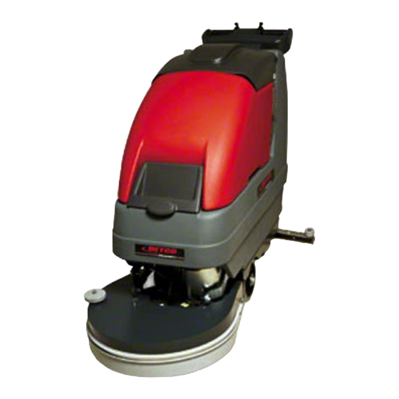
- Page 1 E86014-00 ™ FOREMAN AS20B 20” Automatic Scrubber Operator’s Manual Parts Schematic ©2007 Betco Corporation. All Rights Reserved. 1001 Brown Avenue • Toledo, Ohio 43607-0127 • 888-GO-BETCO • www.betco.com...
- Page 2 Receiving the machine Identification plate Immediately check, when receiving the machine, that all the material indicated on delivery documents has been received and also that the machine has not been damaged in transit. If it has been damaged, this damage must be immediately reported to the shipper and also to our customer service department.
-
Page 3: Symbols Used On The Machine
SYMBOLS USED ON THE MACHINE Cock symbol Used to indicate the cock opening solenoid valve switch Brush symbol Used to indicate the main/brush motor switch Battery charge level symbol. Aspiration motor symbol. Indicates the aspiration motor switch. Brake symbol. Indicates the hand brake engaged signal lamp. Used over the emergency brake lever. Squeegee lift/lower symbol. -
Page 4: General Rules Of Security
GENERAL RULES OF SECURITY The rules below have to be followed carefully in order to avoid damages to the operator and to the machine. Read the labels carefully on the machine. Do not cover them for any reason and replace them immediately if damaged The machine must be used exclusively by authorized staff that has been instructed for its use During the working of the machine, pay attention to other people and especially to the children Do not mix different detergents, avoiding harmful odours... -
Page 5: Machine Preparation
MACHINE PREPARATION 1. HANDLING OF THE PACKED MACHINE The machine is packed in a specific package provided on a pallet for the handling with fork trucks. Do not place more than two packages on top of each other. The total weight is : 187 kg, machines without traction The overall dimensions are: A : 1140 mm MAXIMA 50/450/500/452/502... -
Page 6: Installation Of The Batteries Into The Machine
MACHINE PREPARATION 3. INSTALLATION OF THE BATTERIES INTO THE MACHINE The batteries must be housed in the battery compartment below the recovery tank. They must be handled using special hoisting equipment with suitable grasping systems and designed to support the weight of the batteries. The batteries must also conform to the requirements given in CEI 21-5 standards. -
Page 7: Connection Of The Battery Connector
MACHINE PREPARATION 7. CONNECTION OF THE BATTERY CONNECTOR The battery connector (2) has to be connected to the connector of the machine (1) 8. BATTERIES’ INDICATOR (machines with traction) The batteries’ indicator is digital with 4 fixed positions and a blinking one. The numbers, which appear on the display, show the approximate charge level. - Page 8 MACHINE PREPARATION 11. ADJUSTMENT SQUEEGEE INCLINATION During working operation, the rear rubber has to work slightly tilted backwards and this equally in its whole length for about 5mm. Should it be necessary to increase the rubber bending in the central part, then tilt the squeegee body backwards and turn the adjuster (1) counterclockwise.
-
Page 9: Recovery Tank
MACHINE PREPARATION 13. ASSEMBLY CYLINDRICAL BRUSHES 1. Brake the machine acting upon the lever (1) 2. Lift the brush base acting upon the lever (2) 3. Turn the key (1) into position “0” and take it of 4. Remove the lateral right splash guard (see DISASSEMBLY AND CLEANING OF THE BRUSH UNIT) ATTENTION! Use gloves for this operation in order to protect your hands 1. -
Page 10: Setting For Work
PERFORMANCE 1. SETTING FOR WORK 1. Set the machine up for operation. 2. Check that the parking brake is released (1). 3. Connect the connector to the batteries (2). 4. Turn the main switch key (3) a quarter turn clockwise. The battey led display immediately comes 5. -
Page 11: Overflow Device
PERFORMANCE 2. OVERFLOW DEVICE The machine is equipped with a float, which intervenes when the recovery tank is full causing the closure of the suction hose. In this case, it is necessary to proceed with the emptying of the recovery tank taking off the plug of the exhaust pipe. -
Page 12: On Completion Of The Work
ON COMPLETION OF THE WORK At the end of the work day, before performing any type of maintenance: Close cock (3). Raise base (1). Raise squeegee (2) Turn off brush switch 1). Turn off aspiration motor switch (2). Move the machine to the water disposal point. Turn key (3) to turn the machine off. -
Page 13: Daily Maintenance
DAILY MAINTENANCE 1. CLEANING RECOVERY TANK 1. Open the hood (1). 2. Remove the drain tube (2) from its seat. 3. Empty the tank through the drain tube by turning the knob a few turns and then pulling out the plug. - Page 14 DAILY MAINTENANCE 4. REPLACEMENT OF THE SQUEEGEE RUBBERS Check the squeegee rubber wear and if necessary, change them. To replace them: 1. Take off the suction hose from its coupling. 2. Take off the the pin from the stud bolt. 3.
- Page 15 DAILY MAINTENANCE 3. Clean the hopper as under item 13, paragraph “ON COMPLETION OF THE WORK” 4. Make sure that, at the brushes ends nothing is coiled up like wires, plastic or anything else which does not allow the free brushes rotation. Otherwise: Unscrew the wing nut (1) Take off the plate (2) Remove the splash guard (3)
-
Page 16: Weekly Maintenance
WEEKLY MAINTENANCE CLEANING OF THE SQUEEGEE HOSE Weekly or whenever suction seems to be unsatisfactory check that the squeegee hose is not obstructed. Eventually, clean it proceeding as follows: 5. Take off the hose from its coupling on the squeegee 6. -
Page 17: Troubleshooting Guide
TROUBLE SHOOTING GUIDE 1. INSUFFICIENT WATER ON TO THE BRUSH 4. Check that the cock is open (signal lamp on). 5. Check that there is water in the solution tank. 2. MACHINE DOES NOT CLEAN WELL 6. Check the condition of the brushes and replace if necessary (brushes must be replaced when bristles are 15 mm. - Page 18 SMALTIMENTO ATTENZIONE: Il prodotto, giunto a fine vita, deve essere conferito ai punti di raccolta differenziata messi a disposizione dell'utente finale.
- Page 19 CHOICE AND USE OF BRUSHES POLYPROPYLENE BRUSH (PPL) It is used on all types of floors which are hot water resistant (not more than 60 C). The Polypropylene brush is nonhygroscopic and therefore conserves its characteristics even if working in the wet conditions. NYLON BRUSH It is used on all types of floors with excellent wear and hot water resistance (more than 60 C).
- Page 20 CE STATEMENT OF COMPLIANCE model Maxima 450/500/452/502/650/50 The undersigned company: FIMAP S.p.A. Via Invalidi del Lavoro n.1 37050 Santa Maria di Zevio (VR) states under its own exclusive responsibility that the product FLOOR SCRUBBING MACHINE model Maxima 450/500/452/502/650/50 complies with the provisions of Directives: 98/37/EEC: Machine directive.
- Page 22 Item Applies To Description E83524 Bushing E83895 Wheel 415131 450 B-BT BLADE 500 B-BT E86169 Band Clamp 450 B-BT E83653 Splash guard 500 B-BT E86197 Skirt, Brush Rubber E82312 Bushing E81772 Special Washer E81659 Spring E81769 Shaft E81771 Bearing, 6205 2RS E82667 Belt E83491...
- Page 24 Applies To Description Description ITEM ITEM B-BS E81737 Axle NUT M16x1,5 UNI 7474 414314 B-BS WHEEL WASHER M8 UNI 6592 E86175 Support NUT M8 UNI 7474 203541 SUPPORT SCREW M8x16 UNI 5933 E82529 Caster, Rear Abila SCREW M8x18 UNI 5931 45 BS-BTS 414332 WHEEL WASHER M8 SCHNORR...
- Page 26 ITEM DESCRIPTION E81935 Hose E83810 Knob E82707 Set Screw Hex E82676 Band Clamp 31 1/4" x 7/8" x 1/8" E12560 Squeegee Blade, Polyurethane E12686 Squeegee Blade, Gum Rubber E88240 Squeegee Body E83909 Squeegee Blade, Polyurethane E82608 Band Clamp 29 1/2" x 7/8" x 1/8" E83531 Knob E82329...
- Page 28 ITEM DESCRIPTION 202176 TUBE 416172 CLAMP E81454 Barbed Elbow 203391 SUPPORT E82366 Valve 202188 TUBE E88400 Fitting E86178 O-Ring E83118 Solution Housing Assembly E83119 solution supply filter E82341 Gasket 202172 TUBE E87297 Valve Shaft 203486 CLAMP E83164 Micro Switch E88085 Fitting 1/2 x 3/8 E81035 Solenoid Valve...
- Page 30 DESCRIPTION ITEM 202176 TUBE 416172 CLAMP Barbed Elbow E81454 203391 SUPPORT E82366 Valve 202152 TUBE E88400 Fitting E86178 O-Ring Solution Filter Assembly E83118 E83119 solution supply filter Gasket E82341 202158 TUBE E87297 Valve Shaft Foreman 203486 CLAMP E83164 Micro Switch E88085 Fitting 1/2 x 3/8 Solenoid Valve...
- Page 32 ITEM DESCRIPTION 203491 E83932 Bushing E85767 Bushing E82309 Spring, 11.8x1.2x15mm 412449 203496 KNIFE 203495 STUD BOLT E82837 Spring E82837 Spring 203494 KNIFE 203493 TIE ROD 412450 RETURN 203492 HANDLE E81318 Knob E83832 Flat Washer M8.5x30x3 E81714 Spring WASHER M8 D.24 UNI 6593 SCREW M8X25 UNI 5739 WASHER M8 DIN 6798/A SCREW M8X40 UNI 5739...
- Page 33 Recovery Drain Hose Solution Drain Hose...
- Page 34 ITEM DESCRIPTION ITEM DESCRIPTION E83850 Flat Washer M5x20 SS E81710 Hose Clamp 415147 COVER E88384 Fitting, Recovery Tank Hose 415148 COVER E82790 Air Filter/Shutoff 415144 PANEL E88102 Recovery Filter Assembly E86195 Cover, Bonnet Gray E81786 Hose Clip E88125 E86290 Drain Hose Bushing Foreman 202887 E88126...
- Page 36 DESCRIPTION ITEM 203511 COVER E82493 Grips, Handle 415140 PIPE E81019 O-Ring E82782 Washer E85751 Trigger Lever for Simpla 50 415141 SHAFT 400648 SUPPORT PLATE E82304 Spring, 20.2x1.3x20.8mm Steel Torsion 203513 WASHER E82284 Lever 203510 HANDLE BAR BODY E81663 Fair Lead E88192 415142 SUPPORT PLATE...
- Page 38 DESCRIPTION DESCRIPTION ITEM ITEM 415152 203524 PROTECTION INSTRUMENT BOARD 409296 E83168 Fuse, 3 amp BASE E88244 Fuse Holder for Crewman AS20B E83495 Hour Meter 409869 SUPPORT PLATE SCREW M4X10 UNI 7687 E83926 Fuse 30A faston suction motor WASHER M4 D.12 UNI 6593 E86196 Fuse, 60 amp NUT M4 AUTOBL.
- Page 40 ITEM DESCRIPTION ITEM DESCRIPTION 415152 PROTECTION E82379 Switch 415991 E83168 Fuse, 3 amp GREEN PUSH BUTTON 409296 E88244 Fuse Holder BASE 409869 SUPPORT PLATE E83495 Hour Meter E83926 E83495 Fuse 30A faston Hour Meter E86196 E83315 Fuse, 60 amp Switch Key E81642 Fuseholder SCREW M4X10 UNI 7687...
- Page 42 DESCRIPTION ITEM E81477 Knob 25X50 M8 E82550 Handle - Lever S42 414726 BUSHING 203497 LEVER E85768 Squeegee Cable E81907 203498 SHAFT 415154 CABLE E86154 Fork 203499 BRACKET 409392 LOCK NUT M6 UNI 7474 SCREW M6X16 UNI 5739 LOCK WASHER M6 SCREW M6X20 UNI 5739 NUT M6 UNI 5588 SCREW M5X16 UNI 5739...
- Page 44 ITEM DESCRIPTION E81477 Knob 25X50 M8 203506 HANDLE E82550 Handle - Lever S42 414726 BUSHING 203497 LEVER E85768 Squeegee Cable E81907 203505 SHAFT 202458 SPACER 415138 CABLE E86154 Fork 415154 CABLE E86154 Fork 203499 BRACKET 409392 LOCK NUT M6 UNI 7474 SCREW M6X16 UNI 5739 SCREW M6X30 UNI 5739 WASHER M6 DIN 6798/A...
- Page 46 ITEM DESCRIPTION 202243 DEADENING HOSE E83920 Clamp 9x300 4,8x360 black E83949 Motor, Vacuum Motor, Vacuum 36v 720w 2-Stage E82631 414960 SUPPORT E83944 Sound Deadening Foam 415134 STUD BOLT Stud Bolt Tripla E87975 414686 SPACER E83244 deadening hose E83871 Compression spring 55x2x200 414350 DEADENING HOSE 203523...
- Page 48 ITEM DESCRIPTION 415991 BUTTON - BRUSH- COUPLING E82379 Switch E83316 Key Switch E81358 Switch Flange E83173 Contact, Key Switch E88022 Battery Check Card 24 Volt E83328 Vacuum switch E81706 Signal Lamp Green E83164 Micro Switch E82520 Potentiometer E82794 Microswitch E82794 Microswitch E82403 Double remote control SW 24V...
- Page 51 Doc. 10004809 ADJUSTMENTS Emesso dec -06 MAXIMA Rev. INSPECTIONS Pag. 1 di 7 ADJUSTMENTS AND INSPECTIONS / ALL MODELS READ THE OPERATING AND MAINTENANCE MANUAL Inspection Electrical Equipment 1. Check functionality electrical equipment: switches, motors, solenoid valve. 2. Check functionality control coupling-uncoupling brush, where this is assembled.
- Page 52 Doc. 10004809 ADJUSTMENTS Emesso dec -06 MAXIMA Rev. INSPECTIONS Pag. 2 di 7 8. Push the lever on the handle bar completely forward, read on the tester the tension value: this should be equal to the battery tension, otherwise upon trimmer Vmax (maximum voltage), until the tester indicates...
-
Page 53: Adjustments And Inspections
Doc. 10004809 ADJUSTMENTS Emesso dec -06 MAXIMA Rev. INSPECTIONS Pag. 3 di 7 Adjustment brush – SINGLE BRUSH 450-500 B-BT / MOVEMENT SEMI-AUTOMATIC B 1. Adjust the spring belt tightener at a length of 27mm (1,06 inches) in compression 2. The adjustment lever for the height of the brush base placed under the machine, has to be adjusted always with the brush... - Page 54 Doc. 10004809 ADJUSTMENTS Emesso dec -06 MAXIMA Rev. INSPECTIONS Pag. 4 di 7 Adjust the cup head screw brush rest until the head just touches the even part of the brush on which it rests. The allowance between the head of the screw and the brush must be at most 1mm-2mm, when the brush is coupled and lowered 5.
- Page 55 Doc. 10004809 ADJUSTMENTS Emesso dec -06 MAXIMA Rev. INSPECTIONS Pag. 5 di 7 3. The dimension of the spring belt tightener should be always of 27mm in compression. The models equipped with automatic traction, that means BT, carry out the same operation what the brushes inclination concerns. PS: As the brushes are assembled on flexible couplings, with automatic traction, these models do not need other adjustments regarding the brushes group.
- Page 56 Doc. 10004809 ADJUSTMENTS Emesso dec -06 MAXIMA Rev. INSPECTIONS Pag. 6 di 7 To help the disassembly of the cylindrical brushes, unscrew the screw until the lever is at the first hole of the pressure adjustment. Adjustment brushes base 1. Assemble the joint chain of transmission so that a distance of 2 mm.
- Page 57 Doc. 10004809 ADJUSTMENTS Emesso dec -06 MAXIMA Rev. INSPECTIONS Pag. 7 di 7 2. Adjust the height of the wheels with the suitable hand wheels checking that the rubber has an inclination of around 30°-45° and that it is not too much pressed down onto the floor nor too much lifted.
- Page 58 Service Distributor. If the original part is returned within the warranty policy period from date of delivery for inspection by Betco and is found to be defective the owner will be credited for the cost of replacement parts plus shipping and handling.
Need help?
Do you have a question about the FOREMAN AS20B and is the answer not in the manual?
Questions and answers