BETCO STEALTH ASD26BT Operator And Parts Manual
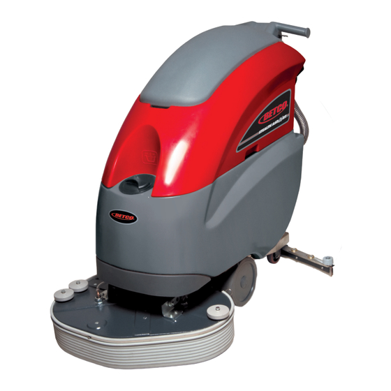
26” automatic scrubber with traction drive
Hide thumbs
Also See for STEALTH ASD26BT:
- Operator and parts manual (52 pages) ,
- Operator and parts manual (56 pages)
Table of Contents
Advertisement
Quick Links
Advertisement
Table of Contents

Related Manuals for BETCO STEALTH ASD26BT


Summary of Contents for BETCO STEALTH ASD26BT
- Page 1 E87026-00 E88064-00 26” Automatic Scrubber ™ STEALTH STEALTH ASD26BT ASD26BT with Traction Drive Operator and Parts Manual 1001 Brown Avenue • Toledo, Ohio 43607-0127 Customer Service: 888-GO-BETCO • Fax: 800-445-5056 • Technical Service: 877-856-5954 • www.betco.com...
-
Page 2: Receiving The Machine
RECEIVING THE MACHINE SERIAL # PLATE Immediately check, when receiving the machine, that all the materials indicated on delivery documents have been received and also that the machine has not been damaged in transit. If it has been damaged, this damage must be immediately reported to the shipper and also to our customer’s service department. -
Page 3: Technical Description
TECHNICAL DESCRIPTION 1.7 (1260) Rated power HP (W) In (mm) 26.0 (660) Working width In (mm) 37.3 (948) Rear squeegee width /h (m 31,970 (2970) Work capacity Water consumption g/ft ∅ in (mm) 14.0 (355) Brush & Pad (diameter) Brush RPM lb (Kg) 99.2 (45) Brush pressure... -
Page 4: Symbols Used On The Machine
SYMBOLS USED ON THE MACHINE Solution valve symbol Used to indicate the water regulation switch Battery charge gauge Battery symbol Open book symbol Used to tell the operator to read the manual before using the machine Maximum solution temperature Located near the solution tank inlet... -
Page 5: General Safety Regulations
Dispose of consumables in accordance with existing laws and codes. When your BETCO machine is ready to be retired its entire component materials must be disposed of properly. They contain oils and electronic components. The machine itself was built using totally recyclable materials. -
Page 6: Machine Preparation
MACHINE PREPARATION 1. HANDLING THE PACKED MACHINE The machine is contained in specific packaging. It is not possible to place more than two packages on top of each other. The total weight is 220 lb (100kg) The overall dimensions of the package are: 49.6 in (1260mm) 28.4 in (720mm) 65.4 in (1660mm) -
Page 7: Battery Installation
Weight 97 lb (44kg) WARNING: Your charger must be set according to the type of battery you install. Call BETCO customer service to ensure correct charger setting after replacement batteries are installed. The batteries must be handled using lifting and transportation means suitable for the weight and dimensions. -
Page 8: Battery Maintenance
MACHINE PREPARATION BATTERY MAINTENANCE For maintenance and recharging, follow the instructions provided by the battery manufacturer. BATTERY DISPOSAL When the battery reaches the end of its working life, it must be disconnected by certified professional, then lifted (using the handles and suitable lifting device) to remove it from the battery compartment. -
Page 9: Connecting The Battery Connector
MACHINE PREPARATION 9. CONNECTING THE BATTERY CONNECTOR The battery connector (2) must be connected to the machine connector (1) 10. BATTERY CHARGE INDICATOR The battery indicator uses LEDs and has 8 positions (7 yellow - charged batteries, and 1 red - run down batteries). WARNING: a few seconds after the red indicator light comes on, the brush motor switches off automatically. -
Page 10: Instrument Panel Components
MACHINE PREPARATION 11. INSTRUMENT PANEL COMPONENTS The instrument panel components are identified as follows: Paddles to activate brushes / traction (located beneath the grip) ON/OFF key switch Battery level / hour-counter display 12. REAR COMPONENTS The rear components are identified as follows: 1- Pedal to raise the brushes 2- Water level tube 3- Solution tank water inlet cap... -
Page 11: Adjusting The Squeegee Height
MACHINE PREPARATION 15. ADJUSTING THE SQUEEGEE HEIGHT The height of the squeegee must be adjusted based on wear and tear of the squeegee. To do this, turn the knob (2) counter clockwise to raise the squeegee, and clockwise to lower it. Note: the right and left wheels must be adjusted to the same level, so the squeegee can work parallel to the floor. -
Page 12: Solution Tank
MACHINE PREPARATION 18. SOLUTION TANK Remove the front inlet cap and check the solution filter is correctly fitted. Check the filter cover (beneath the tank) is correctly closed. 19. SOLUTION TANK Fill the tank with clean water in the front fill location (1) or at the rear fill location (2) at a temperature not exceeding 120°F (50°C). -
Page 13: Regulating The Solution
MACHINE PREPARATION ASSEMBLING THE BRUSH (BASE WITH DOUBLE BRUSH) With the brush deck up, insert the brushes in the brush housing beneath the deck base, turning them until the three pins enter the notches in the plate itself; turn the brush until the pin is pushed towards the coupling spring and is locked into place. -
Page 14: Operation
OPERATION 1. PREPARING TO WORK 1. Connect the battery plug (1) to the machine plug 2. Turn the key (1) of the main switch to the "ON" position (clockwise). The battery charge level indicator lights will immediately come on. 3. Turn on the water valve (2) (the water falls automatically while the brushes are turning). 4. -
Page 15: Overflow Device
OPERATION 2. REVERSE MOVEMENTS (MODELS WITH TRACTION) To activate the reverse direction, just push the command levers (1) counter clockwise. WARNING: when making even brief reverse movements, check the squeegee and base are raised. 4. OVERFLOW DEVICE The machine has a float in the filter basket that trips when the recovery tank is full to stop airflow into the vacuum hose. -
Page 16: Shutting Down The Machine
SHUTTING DOWN THE MACHINE 1. AT THE END At the end of the work, and before carrying out any type of maintenance: 1. Turn off the valve using its handle (1) 2. Raise the brush deck using the pedal (2) 3. -
Page 17: Daily Maintenance
DAILY MAINTENANCE 1. CLEANING THE RECOVERY TANK Raise the vacuum cover (1) and prop it open using the lifting rod on the right-hand side of the lid. Remove the drainage hose (2) from its fitting and empty the tank. Rinse the inside of the tank well with water. Reposition the cover on the machine and replace the drainage hose cap and drainage hose. -
Page 18: Cleaning The Squeegee
DAILY MAINTENANCE 4. CLEANING THE SQUEEGEE Ensure the squeegee is always clean, for better drying results. To clean it you must: 1. Remove the squeegee hose from the nozzle 2. Remove the cotter pins that fix the pins of the squeegee 3. -
Page 19: Weekly Maintenance
WEEKLY MAINTENANCE CLEANING THE SQUEEGEE HOSE Every week, or whenever vacuum seems to be unsatisfactory, check the squeegee hose for obstructions. To clean it, proceed as follows: 1. Remove the hose from the sleeve on the squeegee 2. Remove the other end from the recovery tank 3. -
Page 20: Troubleshooting
TROUBLESHOOTING INSUFFICIENT WATER ON THE BRUSH 1. Check the valve – located beneath the symbol – (1) is turned on. 2. Check there is water in the solution tank. THE MACHINE DOES NOT CLEAN WELL 1. Check the state of wear and tear of the pad and, if necessary, replace it. 2. - Page 21 CHOOSING AND USING THE BRUSHES POLYPROPYLENE BRUSH (PPL) Used on all types of floors. Good resistance to wear and tear, and hot water (no greater than 140°F (60°C)). The Polypropylene brush is non-hydroscopic and therefore retains its characteristics even when working in wet conditions. NYLON BRUSH Used on all types of floors.
- Page 23 Item Part Description QTY. Number Number E20476 Tubing 8 ID x 12 OD x 250 L E20329 Tubing 8 ID x 12 OD x 300 L E86143 Splash Guard E82710 Hose, 8 OD x 5 ID x L 105 E20416 Brush Deck E20628 Support Bracket...
- Page 25 Item Part Description QTY. Number Number E82424 Motor Pulley E85723 Idler Pulley E20428 Tensioner Bracket E20491 Tensioner Arm E81957 Pad Driver Retainer Clip E20007 Stud Bolt E88009 Bushing E88008 Adjuster E87279 Bushing E83823 Screw M5x20/ SS Custom E20615 Flat Washer M6.5x18x4 E20546 Spacer E86216...
- Page 27 Item Part Description QTY. Number Number E82689 Spring E20219 Brush Deck Lift Arm Weldment E20220 Brush Deck Lift Arm Linkage E20062 Brush Deck Lift Idler Arm E20282 Brush Deck Lift Foot Pedal E20283 Foot Pedal Latch Plate E20063 Bushing E88279 Micro Switch Sealed E20088 Hex Bolt M6x18 Zinc...
- Page 29 Item Part Description QTY. Number Number E82275 Stud Bolt M10 Custom E82280 Squeegee Pin E81834 Squeegee Blade Front E81835 Squeegee Support Blade Rear E20617 Band Clamp E20012 Band Clamp E20573 Squeegee Shoe E20498 Brass Washer - Custom E82307 Squeegee Vacuum Adapter E20572 Squeegee Shoe Extender E20077...
- Page 31 Item Part Description QTY. Number Number E20623 Squeegee Yoke ASM E20010 Pivot Pin E82389 Eye Bolt E82265 Adjuster, Squeegee E83331 Knob E85776 Pivot Connector E20078 Squeegee Wheel Support E81880 Squeegee Yoke E20079 Threaded Adjuster Rod E20080 Ballast 1.10 E86252 Latch, Squeegee Connector 1.11 E20090 Hex Bolt M6x25 Zinc...
- Page 33 Item Part Description QTY. Number Number E20003 Axle Shaft ASM E20478 Axle Shaft E20482 Spacer E20081 Bearing Block E83923 Bearing E20013 Spacer E20492 Brake Arm Weldment E20407 Main Frame Weldment E20221 Frame Bracket E20222 Plate E20518 Brake Lever ASM E20595 Brake Lever E20522 Brake Lever Bracket...
- Page 35 Item Part Description QTY. Number Number E12666 Squeegee Vacuum Hose E88287 Hose, Glass Reinforced 17 OD x 12 ID x 200 L E88288 Hose, Glass Reinforced 17 OD x 12 ID x 820 L E20228 Recovery Tank ASM E82341 Gasket E20107 Screw, Pan Hd Phil Self Tap M4.2x16 SS E20432...
- Page 37 Item Part Description QTY. Number Number E20629 Recovery Tank Cover ASM E20599 Vacuum Motor 24VDC 550W E88290 Hose, Vacuum E20064 Support Bracket E20440 Sound Deadening Foam E88289 Gasket E81006 Vacuum Splash Guard E88200 Vacuum Motor 36VDC 550W E20084 Hex Bolt M5x16 SS E20102 Screw, Pan Hd Phil Self Tap M4.2x13 SS 1.10...
- Page 39 Item Part Description QTY. Number Number E20004 Tubing 12 ID x 200 L E20530 Tubing 12 ID x 460 L E82693 Hose, 17 OD x 12 ID x L 420 E82447 Barbed Nipple E88207 Filter E20457 Bracket E20493 Tubing 12 ID x 560 L E20463 Instrument Panel ASM E20332...
- Page 41 Item Part Description QTY. Number Number E82351 Key Switch E83173 Key Switch Contact E83316 Key Switch E83316 Key Switch E81358 Switch Flange E83315 Switch Key E20223 Drive Control E20330 E20574 Bushing E20556 Plate E81763 E82304 Spring E20341 Hex Bolt M4x16 Zinc E20242 Pan Hd Phil Machine Screw M3x20 Zinc E20243...
- Page 43 Item Part Description QTY. Number Number E20065 Bracket E20536 Buss Bar E20646 Variable Speed Controller E83628 Contactor 24VDC E20097 Hex Bolt M8x40 SS E20248 Hex Nut, M4x4 Zinc E83672 Hex Jam Nut, M8x5 SS E20115 Hex Nut, M8x6.5 Brass E20479 Spring Nut M5 E20124 Flat Washer M8x17x1.6 SS...
- Page 45 Item Part Description Number Number E82351 Key Switch E88293 Hour Meter E82511 Variable Speed Controller E83628 Contactor 24VDC E83628 E83628 Contactor 24VDC Contactor 24VDC E83170 Fuse, 80 Amp E83952 Circuit Breaker 30A E83959 Circuit Breaker 20A E82322 Solenoid Valve E81035 Solenoid Valve E20402 Electrical Connector 30A...
- Page 47 Electric harness inspaction 1. Verify the functionality of the variable speed control card. 2. If necessary adjust the traction card as follow: • Lift up at least one of the traction wheel • Remove the handle to guarantee access to the electric plant •...
- Page 48 Battery check card adjustment 1. Verify that turning on the machine the battery check card has the following starting sequence: Turning on of the LED which correspond to the set-up (red LED = “0”). Turning on of all the LEDs (check of the lamps) Turning on of the LEDs depending on the charge of the battery 2.
- Page 49 Water plant inspection 1. Verify the cleanness and functionality of the solution filter under the solution tank plug. 2. Check cleanness and sealing of the solution filter. 3. Fill completely the solution tank. 4. Verify the sealing of the hoses, solenoid valve and the water...
- Page 50 Brake adjustment 1. Fix the brake wire to the chassis screw in up completely the sheath to the support. 2. Adjust the pads on the wheels to let the machine be blocked when the brake lever reach the third step. 3.
- Page 51 6. Vacuum microswitch adjustment: 7. Adjust the vacuum micro switch in way that when the cam on the squeegee lever push the microswitch there is about 0.5 mm of clearance of the microswitch lever. Brush assembly micro switch adjustment 1. Verify that when the pedal is hooked the micro switch switched and the micro switch lever has about 0.5 mm of clearance.
- Page 52 5. Verify that the M8 bolt that fix the arm to the third point let the brush assembly to move longitudinally to let the brush base to adapt itself to the floor. 6. Verify that the brushes can be removed from the brush base and that there is space enough to let the buttons of the brushes pass under the brush connection.
- Page 53 4. Verify the pressure of the squeegee on the floor. Verify that the pressure to the spring and to the squeegee weight is enough to bend the squeegee rubbers and let the squeegee wheels touch the floor. 5. Verify that the pressure is not too much to prevent a fast wearing out of the squeegee wheels in swerving.
- Page 54 Service Distributor. If the original part is returned within the warranty policy period from date of delivery for inspection by Betco and is found to be defective the owner will be credited for the cost of replacement parts plus shipping and handling.
Need help?
Do you have a question about the STEALTH ASD26BT and is the answer not in the manual?
Questions and answers