Table of Contents
Advertisement
Quick Links
Advertisement
Table of Contents
Troubleshooting

Related Manuals for BETCO STEALTH DRS24BT


Summary of Contents for BETCO STEALTH DRS24BT
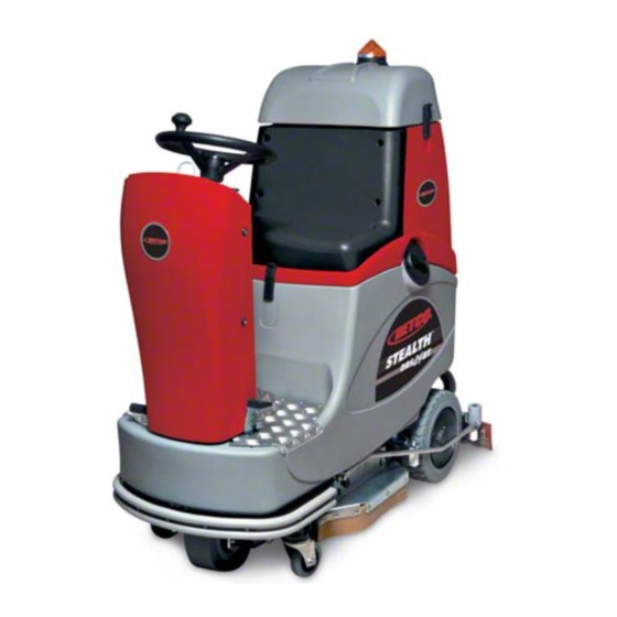
- Page 1 E87032-00 E88065-00 24” Automatic Rider ™ STEALTH STEALTH DRS24BT DRS24BT Scrubber Operator and Parts Manual 1001 Brown Avenue • Toledo, Ohio 43607-0127 Customer Service: 888-GO-BETCO • Fax: 800-445-5056 • Technical Service: 877-856-5954 • www.betco.com...
-
Page 2: Table Of Contents
TABLE OF CONTENTS RECEIVING THE MACHINE........3 - 4 GENERAL SAFETY REGULATIONS ......... 5 MACHINE PREPARATION ..........6 - 9 OPERATION ............10 - 12 SHUTTING DOWN THE MACHINE ........ 13 DAILY MAINTENANCE ..........14 WEEKLY MAINTENANCE ..........15 TROUBLESHOOTING ..........16 - 18 BRUSH SELECTION ............. -
Page 3: Receiving The Machine
RECEIVING THE MACHINE On receipt of the machine, you must immediately make sure you have received all the material indicated in the accompanying documentation and that the machine has not been damaged during shipment. Any damage noted should be reported to the carrier immediately and our customer service department should be notifi... - Page 4 ™ TECHNICAL DESCRIPTION Measurement Unit Stealth DRS24BT Working width In (mm) 24 (610) Squeegee width In (mm) 33 (850) Productivity /h (m 39,400 (3660) Brushes in (mm) 24.0 (610) Brush RPM Brush pressure lb (Kg) 77 (35) Brush motor HP (V / W) 0.75 (560) Drive motor HP (V / W)
-
Page 5: General Safety Regulations
• Do not use the machine on surfaces with a gradient greater than that indicated on the serial tag. • When the machine is parked, remove the key and apply the parking brake. • If you experience poor operation, perform standard maintenance. If operational problems remain, contact a BETCO techni- cal service center. -
Page 6: Machine Preparation
MACHINE PREPARATION 1. HANDLING THE PACKAGED MACHINE The machine is palletized so that it may be moved with forklift trucks. The pallets should not be double stacked. The total weight 775 pounds. The dimensions of the package are: A : 61 inches B : 40 inches C : 69 inches 2. - Page 7 MACHINE PREPARATION 4. CONNECTING THE BATTERY CONNECTOR A. Connect the battery connector to the machine connector. B. Place the connectors in the battery compartment. WARNING: This must be done by qualifi ed personnel only. Incor- rect or faulty connection of the wires to the connector could cause serious injury to people and damage to the machine.
- Page 8 MACHINE PREPARATION 7. BATTERY CHARGE INDICATOR The battery charge indicator is digital with four fi xed states and one fl ashing state. The numbers displayed indicate the approximate charge status. 4 = maximum charge, 3 = 3/4 charged, 2 = 1/2 charged, 1 = 1/4 charged, STOP = batteries completely discharged (fl...
-
Page 9: Machine Preparation
MACHINE PREPARATION 10. MOUNTING THE PAD DRIVER A. Connect the battery connector. B. Turn the key to the ON position. C. Use the switch to raise the brush deck. D. Turn the key to the OFF position and remove it from the key switch. WARNING: Mounting the brush with the power on could lead to injury. -
Page 10: Operation
OPERATION 1. PREPARING FOR OPERATION A. Prepare the machine. B. Sit in the driving position. C. Check that the parking brake is released. D. Turn the ON/OFF key a quarter of a turn clockwise. The battery and hour meter display turns on immediately. E. - Page 11 OPERATION The machine will not move unless the operator is seated correctly in the seat. When the batteries are fully discharged, a fl ashing red LED appears on the display and the brush motor turns off automatically. You must recharge the bat- teries as soon as possible.
- Page 12 OPERATION 3. DRIVE AND BRAKES This machine is equipped with an electronically controlled drive. To move the machine, you must turn the key (1) then move the switch lever (2) forward (forward movement) or backward (reverse movement). The machine starts to move when the speed control pedal is depressed.
-
Page 13: Shutting Down The Machine
SHUTTING DOWN THE MACHINE 1. After work is complete and before performing maintenance, perform the fol- lowing operations: 2. Turn off the water control knob (1) by pressing down on the knob 3. Place the brush deck raise/lower switch in the raised position until the brush deck is completely raised. -
Page 14: Daily Maintenance
DAILY MAINTENANCE 1. CLEANING THE FILTER AND RECOVERY TANK A. Empty the tank through the drain hose. B. Rinse the tank and clean the hose cap. C. Replace the cap on the drain hose. D. Replace the drain hose and cap following the same process in reverse. WARNING: This must be done wearing gloves to protect from con- tact with dangerous solutions. -
Page 15: Weekly Maintenance
WEEKLY MAINTENANCE 1. REPLACING THE SQUEEGEE BLADES If the rear squeegee blade is worn and does not dry effi ciently, the wiping edge can be changed as follows: A. Remove the squeegee from the machine B. Remove the locking latch C. -
Page 16: Troubleshooting
TROUBLESHOOTING GUIDE 1. INSUFFICIENT WATER ON THE BRUSH A. Make sure the water control knob is open. B. Make sure there is water in the solution tank. C. Water comes out only when the machine moves forward. D. Clean the solution fi lter. E. -
Page 17: Troubleshooting Guide
TROUBLESHOOTING GUIDE 4. THERE IS NO VACUUM SUCTION Confi rm that the squeegee switch is in the lowered or center position, this low- ers the squeegee blade. 5. THE MACHINE DOES NOT START A. The operator must be sitting in the driver's seat. B. - Page 18 • Squeegee raising/lowering actuator If a resettable fuse trips, turn the key switch to the OFF position (1), wait for a few seconds, then turn it back to the ON position (2). If the problem persists, contact an authorized BETCO technical service center.
-
Page 19: Brush Selection
BRUSH SELECTION POLYPROPYLENE BRUSH (PPL) Used on all types of fl oors. Good resistance to wear and tear, and hot water (no greater than 140°F (60°C)). NYLON BRUSH Used on all types of fl oors. Excellent resistance to wear and tear and hot water (even over 140°F (60°C)). ABRASIVE BRUSH The bristles of this type of brush are coated with highly aggressive abrasives. -
Page 20: Parts Diagrams And Listings
PARTS DIAGRAM... - Page 21 PARTS LISTING Item# Part # Description Qty. Item# Part # Description Qty. E20654 Gasket 5 .18.1 E81794 Valve Body, Solenoid E20281 Splash Guard ASM Right Side 5.18.2 E81795 Solenoid E20030 Splash Guard Bracket 5.19 E83932 Bushing E83895 Wheel 80 OD x 23 W 5.20 E83354 Spring...
- Page 22 PARTS DIAGRAM...
- Page 23 PARTS LISTING Item# Part # Description Qty. Item# Part # Description Qty. E20590 Gear Housing E20083 Gasket E20618 Gearbox Cover E82399 Shaft Key E20009 Bearing Cup E81708 Oil Seal E20075 Bearing Retainer E20092 Bevel Gear Shaft E20339 Bevel Gear Shaft E20355 Oil Seal E81699...
- Page 24 PARTS DIAGRAM...
- Page 25 PARTS LISTING Item# Part # Description Qty. Item# Part # Description Qty. E20006 Bushing E81874 Flat Washer M8x17x1.6 Zinc E20205 Actuator Pivot Arm Weldment E81918 Flat Washer M9x32x2.5 Zinc E20310 Actuator Pivot Arm Weldment E83704 Lock Washer M8x13x2.2 Zinc E20033 Mounting Plate E83903 Shim Washer M14x22x0.3...
- Page 26 PARTS DIAGRAM...
- Page 27 PARTS LISTING Item# Part # Description Qty. Item# Part # Description Qty. E82275 Stud Bolt M10 Custom E82376 Latch E81664 Squeegee Blade, Front E20435 Nyloc Hex Nut, M3 SS E20404 Squeegee Shoe E20560 Band Clamp E83355 Hex Bolt M6x10 SS E20137 Band Clamp E81672...
- Page 28 PARTS DIAGRAM...
- Page 29 PARTS LISTING Item# Part # Description Qty. Item# Part # Description Qty. 23.27 E88222 Bushing E20643 Spacer E20275 Guide Arm 23.28 E88176 Latch E20439 Spacer 23.29 E20460 Hex Jam Nut, M10X6 SS E20036 Bushing 23.30 E20580 Clevis E20037 Bumper Wheel Bracket 23.31 E20414 Caster...
- Page 30 PARTS DIAGRAM...
- Page 31 PARTS LISTING Item# Part # Description Qty. Item# Part # Description Qty. E82397 Hose, 12 OD x L 100 E83796 Screw, Pan Hd Phil Self Tap M4.2x16 Zinc E20277 Battery Tray E88042 Flat Hd Soc Machine Screw M6x16 Zinc E20640 Main Frame Weldment E83935 Hose Clamp...
- Page 32 PARTS DIAGRAM...
- Page 33 PARTS LISTING Item# Part # Description Qty. Item# Part # Description Qty. E20608 Special Hex Nut M14 E20529 Steering Wheel E20203 Switch Mounting Bracket E20232 Shaft Key E20471 Steering Drive Shaft E83974 Hex Bolt M6x30 Zinc E20456 Steer Shaft Hub ASM E81917 Hex Bolt M8x20 Zinc E20081...
- Page 34 PARTS DIAGRAM 6.47 6.14...
- Page 35 PARTS LISTING Item# Part # Description Qty. Item# Part # Description Qty. E22110 Pinion 6.30 E22126 Grease Nipple E20558 Spacer 6.31 E82492 Master Chain Link E20204 Switch Cam Arm 6.32 E20442 Button Hd Soc Machine Screw, M5x16 Zinc E22111 Bracket 6.33 E22127 Sealing Ring...
- Page 36 PARTS DIAGRAM...
- Page 37 PARTS LISTING Item# Part # Description Qty. Item# Part # Description Qty. E20626 Clevis Pin E20421 Fender Washer M8.2x30x6 Zinc E20021 Brake Pedal E20464 Hub Cap E20022 Brake Lever Pivot Arm E20357 Hex Bolt M8x14 Zinc E20274 Bushing 5.10 E83833 Hex Bolt M8x25 Zinc E20353 Rear Transport Wheel ASM...
- Page 38 PARTS DIAGRAM...
- Page 39 PARTS LISTING Item# Part # Description Qty. Item# Part # Description Qty. E20585 Seat Prop E83278 Flat Washer M6.5x24x2 Zinc E20211 Cam Plate E82774 Flat Washer M6x12x1.6 SS E20541 Pipe E83798 Flat Washer M6x30x3 PVC Black E83850 Flat Washer M5x20 SS E81874 Flat Washer M8x17x1.6 Zinc E82429...
- Page 40 PARTS DIAGRAM...
- Page 41 PARTS LISTING Item# Part # Description Qty. Item# Part # Description Qty. E20462 Hose, Vacuum E81618 Flat Washer M5x10x1 SS E82362 Hose, Vacuum E20122 Flat Washer M5x15x1.5 SS E83614 Vacuum Motor 36VDC E20125 Flat Washer M8x17x1.6 SS E88200 Vacuum Motor 36VDC 550W E82790 Air Filter/Shutoff 3.1.1...
- Page 42 PARTS DIAGRAM...
- Page 43 PARTS LISTING Item# Part # Description Qty. Item# Part # Description Qty. E20649 Tubing 14 ID x 250 L E20087 Hex Bolt M6x16 SS E82447 Barbed Nipple E83795 Hex Bolt M8x16 Zinc E88207 Filter E86194 Hex Bolt M5x20 SS E20512 Filter, Body E82317 Hex Jam Nut, M5X3.5 Zinc...
- Page 44 PARTS DIAGRAM...
- Page 45 PARTS LISTING Item# Part # Description Qty. Item# Part # Description Qty. E20653 Stud Pin 5.2.13 E88204 Spring E20015 Pivot Arm 5.2.14 E20086 Hex Bolt M5x25 Zinc E20016 Console Frame 5.2.15 E20089 Hex Bolt M6x22 Zinc E20453 Bushing 5.2.16 E82691 Spring 5.2.17 E83857...
- Page 46 PARTS DIAGRAM...
- Page 47 PARTS LISTING Item# Part # Description Qty. Item# Part # Description Qty. E88144 Pad Holder, 24 Center Lock E20213 Traction Motor ASM 24VDC 400W E82367 Center Lock E20487 Squeegee Shoe ASM E20603 Brush, 24"" 0.9 Nylon E81664 Squeegee Blade, Front E82457 Brush, 24""...
-
Page 48: Electrical Diagram
ELECTRICAL DIAGRAM F9 F8 F7 100A... - Page 49 ELECTRICAL LISTING Item# Part # Description Item# Part # Description E83495 Hour Meter E82824 Potentiometer E88022 Battery Check Card 24 Volt E82270 Micro Switch E20520 Warning Light E82270 Micro Switch E20559 2 Way Rocker Switch ASM - Amber E82270 Micro Switch E88202 1 Way Momentary Rocker Switch ASM - Green E82567...
-
Page 50: Electrical System
ELECTRICAL DIAGRAM Rxe185 Rxe185 Rxe185 Rxe375 Rxe185 Rxe185 MANIPOLATORE 9 100A PROGRAMMING CONSOLE CONSOLE SERVICES The console allows to: • Program the traction card to have a customized performance of the traction. • Test and check the electric values and the electric circuit conditions (only the traction part). -
Page 51: Alarm And Warning Table
ALARM AND WARNING TABLE Alarms or warnings stop the machine. The number of the alarm occurred is readable by the console display or counting the fl ashes of the alarm led. The number of fl ashes matches with the alarm number (for example 4 fl ashes are equal to A4). Message Purpose Alarm... -
Page 52: Parameters
PARAMETERS Name Default Description Parameters of default (F0=2), switch off and switch on again F 1 * IGSL F 2 * PGSL F 3 * IGCL F 4 * PGCL 50 Ramp Acceleration (10=1s) 50 Ramp Deceleration when reversing (10=1s) Deceleration ramp when stopping (10=1s) Limit of current [A] - Imax Decrease reverse gear [%]... -
Page 53: Potentiometer Calibration
POTENTIOMETER CALIBRATION 1. Be sure that the machine is turned off. 2. Connect the programming console to the traction card and then turn on the machine. 3. A check out message (like - –3 or similar will fl ash few times) will be shown and then “0” will appear. 4. -
Page 54: Speed Control Pedal Adjustment
SPEED CONTROL PEDAL ADJUSTMENT 1. Verify that if the potentiometer gears are at the end of stroke, the speed control pedal touches the bottom plate. This is important to avoid the gears breaking down for a too high pressure. 2. If an adjustment is needed: •... -
Page 55: Steering And Traction Adjustment
STEERING AND TRACTION ADJUSTMENT 1. Check the tension of the steering chain. If you have to adjust it do as follows: • Unscrew the front M8 screws which lock the castle wheel support. • Unscrew the M8 nut on the lateral screw. •... -
Page 56: Brush Deck Adjustment
BRUSH DECK ADJUSTMENT 1. Put the machine on a level fl oor. Check when lowering the brush deck, the front of the brush touches the fl oor, and the rear edge of the brush is 1/4 inch off the fl oor. 2. -
Page 57: Squeegee Adjustment
SQUEEGEE ADJUSTMENT 1. Check that squeegee lifts up and lowers correctly. 2. If the squeegee has bad movement, check that the squeegee micro switches are properly adjusted to stroke ends. 3. If necessary adjust the micro switches as follows: • Remove the plastic cover using a screw driver. •... -
Page 58: Squeegee Lift Adjustment
SQUEEGEE LIFT ADJUSTMENT 1. Adjust the tie rods to their end points tightening them in completely. • Adjust the tie rod end of stroke bumpers. • Unscrew the M8 screws. • The end of stroke bumpers have to be located such that when the tie rod is pushed toward the machine the distance between the tie rod and the rear wheel is about 1/8 of an inch. - Page 59 SQUEEGEE LIFT ADJUSTMENT 4. Check that, when the squeegee is completely pushed to the side of the machine, the bumper wheels have a distance to the rear wheels of about 0.1 inches. If necessary unscrew the joints of the side bars to increase this distance as follows: •...
-
Page 60: Vacuum Test
VACUUM TEST 1. Check the cleanliness and the functionality of the fi lter – fl oat. 2. Check the sealing of the gasket on the recovery tank. 3. Check the connections of the vacuum hoses and of the squeegee hose. TEST WATERING SYSTEM 1. -
Page 61: Check List
CHECK LIST Operational testing of the machine Check the function of switches and signal lamps. Check the function of the operator seat micro switch. Check the function of the speed control pedal. Check the function of the brush deck. Check the function of the brush motor. Check the function of the sideways squeegee movement. -
Page 62: Maintenance Schedule
MAINTENANCE SCHEDULE Stealth DRS24BT DAILY SUGGESTED HOURS 1,000 Suggested replacement e t a e l r n f i s s e y r a y l i a BATTERIES , s e l t c e n o i u l p . -
Page 63: Wear Items
WEAR ITEMS Stealth DRS24BT PART DESCRIPTION NUMBER E88208 Splash Guard E88209 Splash Guard E82260 Carbon Brush E81664 Squeegee Blade, Front E81665 Squeegee Blade, Rear, Shore 33 E88213 Squeegee Blade - Rear Shore 40 E88214 Squeegee Blade - Rear Shore 40 Poly... -
Page 64: Warranty
Service Distributor. If the original part is returned within the warranty policy period from date of delivery for inspection by Betco and is found to be defective the owner will be credited for the cost of replacement parts plus shipping and handling.
Need help?
Do you have a question about the STEALTH DRS24BT and is the answer not in the manual?
Questions and answers