Table of Contents
Advertisement
Quick Links
7KT333
User's Manual Version 1.0
The information presented in this publication has been
made carefully for reliability; however, no responsibility
is assumed for inaccuracies. Specifications are subject
to change without notice.
IBM, PC/AT, and PC/XT are trademarks of Interna-
tional Business Machines Corporation.
Socket462 is a trademark of AMD Corporation
AWARD is a registered trademark of Phoenix
Software Inc.
MS-DOS and WINDOWS NT are registered trade-
marks of Microsoft Corporation.
Trademarks and/or registered trademarks are the
properties of their respective owners.
i
Advertisement
Table of Contents

Subscribe to Our Youtube Channel
Related Manuals for Acorp 7KT333


Summary of Contents for Acorp 7KT333
- Page 1 7KT333 User's Manual Version 1.0 The information presented in this publication has been made carefully for reliability; however, no responsibility is assumed for inaccuracies. Specifications are subject to change without notice. IBM, PC/AT, and PC/XT are trademarks of Interna- tional Business Machines Corporation.
- Page 2 1. Mnthdranarc Ddrcriotinn 1. Mnthdranarc Ddrcriotinn 1. Mnthdranarc Ddrcriotinn 1.1 Intrnctctinn 1.1 Packagd Cnntdntr 1.3 Fdattrdr 1.3 7KT333 Mnthdranarc Kayntt 1.5 CPU Inrtallatinn 1.6 DDR RDRAM Inrtallatinn 1.7 Cnnndctnrr & Jtmodr Rdtting 1.7.1 Back Pandl Cnnndctnrr 1.7.1.1 PR.1 Mntrd.Kdyanarc CNMM.
- Page 3 T T T T T able of Contents able of Contents able of Contents able of Contents able of Contents 1.7.15 Rmart Pandl Ftnctinn (notinnal( 1-10 1.7.15.1 Pnrt 80 Ddatg Ftnctinn(RP-J6( 1-11 1.7.15.1 Rdcnnc BINR Cnnndctnr(RP-J1( 1-11 1.7.15.3 AUX KIMD Cnnndctnr(RP-J5( 1-11 1.7.15.3 Frnnt CNM1 Hdacdr Cnnn.(RP-J7( 1-11...
-
Page 4: Package Contents
1.1 Introduction 1.1 Introduction 1.1 Introduction 1.1 Introduction The 7KT333 motherboard is designed for using AMD Athlon and Duron Front Side Bus Frequency 200/266MHz CPU, which utilize the Socket-462 design and the memory size expandable to 3.0GB. This motherboard use the latest VIA KT333 chipset, appling... - Page 5 Chaosdr 1 Chaosdr 1 Chaosdr 1 Chaosdr 1 Chaosdr 1 Mnshdranarc Cdrbrhoshnn Mnshdranarc Cdrbrhoshnn Mnshdranarc Cdrbrhoshnn Mnshdranarc Cdrbrhoshnn Mnshdranarc Cdrbrhoshnn 1.3 Features 1.3 Features 1.3 Features 1.3 Features 1.3 Features CPU Processor ● Support AMD Athlon 700MHz~Athlon XP 2000+ processor with 200/266MHz FSB. ●...
-
Page 6: Flash Memory
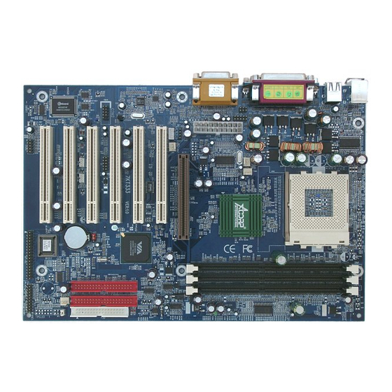
Chaosdr 1 Chaosdr 1 Chaosdr 1 Chaosdr 1 Chaosdr 1 Mnshdranarc Cdrbrhoshnn Mnshdranarc Cdrbrhoshnn Mnshdranarc Cdrbrhoshnn Mnshdranarc Cdrbrhoshnn Mnshdranarc Cdrbrhoshnn 1.3 Features 1.3 Features 1.3 Features 1.3 Features 1.3 Features Universal Serial Bus ● Supports two back Universal Serial Bus(USB)Ports and two front Universal serial Bus(USB)Ports. - Page 7 Chaosdr 1 Chaosdr 1 Chaosdr 1 Chaosdr 1 Chaosdr 1 Mnshdranarc Cdrbrhoshnn Mnshdranarc Cdrbrhoshnn Mnshdranarc Cdrbrhoshnn Mnshdranarc Cdrbrhoshnn Mnshdranarc Cdrbrhoshnn 1.4 7KT333 Motherboard Layout 1 - 4 1 - 4 1 - 4 1 - 4 1 - 4...
- Page 8 Chaosdr 1 Chaosdr 1 Chaosdr 1 Chaosdr 1 Chaosdr 1 Mnshdranarc Cdrbrhoshnn Mnshdranarc Cdrbrhoshnn Mnshdranarc Cdrbrhoshnn Mnshdranarc Cdrbrhoshnn Mnshdranarc Cdrbrhoshnn 1.4 7KT333 Layout USB1 COM1 Printer FAN3 FAN2 COM2 Speak out Line in GAME1 MIC in AGP SLOT FAN1 PCI1...
- Page 9 Chaosdr 1 Chaosdr 1 Chaosdr 1 Chaosdr 1 Chaosdr 1 Mnshdranarc Cdrbrhoshnn Mnshdranarc Cdrbrhoshnn Mnshdranarc Cdrbrhoshnn Mnshdranarc Cdrbrhoshnn Mnshdranarc Cdrbrhoshnn 5. AGP Slot 6. Floppy Connector 7. IDE Connectors (IDE1/IDE2) 8. North Bridge (VIA KT333) 9. South Bridge (VIA VT8233A) 10.
- Page 10 Chaosdr 1 Chaosdr 1 Chaosdr 1 Chaosdr 1 Chaosdr 1 Mnshdranarc Cdrbrhoshnn Mnshdranarc Cdrbrhoshnn Mnshdranarc Cdrbrhoshnn Mnshdranarc Cdrbrhoshnn Mnshdranarc Cdrbrhoshnn 1.5 CPU Installtion The motherboard operates with Socket 462 for AMD Athlon and Duron processor. The CPU should always has a Heat Sink and cooling fan attached to prevent overheating.
- Page 11 Chaosdr 1 Chaosdr 1 Chaosdr 1 Chaosdr 1 Chaosdr 1 Mnshdranarc Cdrbrhoshnn Mnshdranarc Cdrbrhoshnn Mnshdranarc Cdrbrhoshnn Mnshdranarc Cdrbrhoshnn Mnshdranarc Cdrbrhoshnn 1.6 DDR SDRAM Installtion The motherboard supports a maximized 3GB memory. It provides three 184-pin unbuffered DDR sockets. It supports 64MB to 1GB DDR memory module.
-
Page 12: Connectors & Jumpers Setting
Chaosdr 1 Chaosdr 1 Chaosdr 1 Chaosdr 1 Chaosdr 1 Mnshdranarc Cdrbrhoshnn Mnshdranarc Cdrbrhoshnn Mnshdranarc Cdrbrhoshnn Mnshdranarc Cdrbrhoshnn Mnshdranarc Cdrbrhoshnn 1.7 Connectors & Jumpers Setting 1.7.1 Back Panel I/O Connectors The motherboard provides the following back panel connectors: MIDI/(GAME) Port Parallel (Printer) Port (15-pin Female) (25-pin Female) -
Page 13: Joystick / Midi Connector
Chaosdr 1 Chaosdr 1 Chaosdr 1 Chaosdr 1 Chaosdr 1 Mnshdranarc Cdrbrhoshnn Mnshdranarc Cdrbrhoshnn Mnshdranarc Cdrbrhoshnn Mnshdranarc Cdrbrhoshnn Mnshdranarc Cdrbrhoshnn 1.7.1.3 The Serial Interfaces: COM1 / COM2 The serial interface port is sometimes refered to as an RS-232 port or an asynchronous communication port. Mice, printers, modems and other peripheral devices can be connected to a serial port. - Page 14 Chaosdr 1 Chaosdr 1 Chaosdr 1 Chaosdr 1 Chaosdr 1 Mnshdranarc Cdrbrhoshnn Mnshdranarc Cdrbrhoshnn Mnshdranarc Cdrbrhoshnn Mnshdranarc Cdrbrhoshnn Mnshdranarc Cdrbrhoshnn 1.7.2 ATX Power Connector: ATX This connector supports the power button on-board. Using the ATX power supply, functions such as Modem Ring Wake- Up and Soft Power Off are supported on this motherboard .
-
Page 15: Hard Disk Connectors: Ide1/Ide2
Chaosdr 1 Chaosdr 1 Chaosdr 1 Chaosdr 1 Chaosdr 1 Mnshdranarc Cdrbrhoshnn Mnshdranarc Cdrbrhoshnn Mnshdranarc Cdrbrhoshnn Mnshdranarc Cdrbrhoshnn Mnshdranarc Cdrbrhoshnn 1.7.3 Floppy Disk Connector: FDC This connector supports the provided floppy drive ribbon cable. After connecting the single end to the board, connect those two plugs on the other end to the floppy drives. -
Page 16: Cd Audio-In Connectors: Cd-In1/Cdin2
Chaosdr 1 Chaosdr 1 Chaosdr 1 Chaosdr 1 Chaosdr 1 Mnshdranarc Cdrbrhoshnn Mnshdranarc Cdrbrhoshnn Mnshdranarc Cdrbrhoshnn Mnshdranarc Cdrbrhoshnn Mnshdranarc Cdrbrhoshnn Pin Fan2/3 Pin Fan1/4 Definition Definition Ground Ground +12VDC +12VDC Signal These connectors support cooling fans of 1Amp or less. Orientate the fans so that the heatsink fins allow airflow to go across the onboard heat sink(s) instead of the expansion slots. -
Page 17: Wake-On-Lan Connector: Wol
Chaosdr 1 Chaosdr 1 Chaosdr 1 Chaosdr 1 Chaosdr 1 Mnshdranarc Cdrbrhoshnn Mnshdranarc Cdrbrhoshnn Mnshdranarc Cdrbrhoshnn Mnshdranarc Cdrbrhoshnn Mnshdranarc Cdrbrhoshnn 1.7.7 Wake-On-LAN Connector: WOL USB1 COM1 Printer FAN3 FAN2 COM2 Speak out Line in GAME1 MIC in Definition AGP SLOT FAN1 5V_SB PCI1... -
Page 18: Panel Connector
Chaosdr 1 Chaosdr 1 Chaosdr 1 Chaosdr 1 Chaosdr 1 Mnshdranarc Cdrbrhoshnn Mnshdranarc Cdrbrhoshnn Mnshdranarc Cdrbrhoshnn Mnshdranarc Cdrbrhoshnn Mnshdranarc Cdrbrhoshnn 1.7.9 Front USB Port Connector: USB2 USB1 COM1 Printer FAN3 FAN2 COM2 Speak out Line in GAME1 MIC in USB2 AGP SLOT FAN1 PCI1... -
Page 19: Speaker Connector (Speaker)
Chaosdr 1 Chaosdr 1 Chaosdr 1 Chaosdr 1 Chaosdr 1 Mnshdranarc Cdrbrhoshnn Mnshdranarc Cdrbrhoshnn Mnshdranarc Cdrbrhoshnn Mnshdranarc Cdrbrhoshnn Mnshdranarc Cdrbrhoshnn ATX Power Switch (PW_BN) The system power is controlled by a momentary switch connected to this lead. Pushing the button once will switch the system ON. -
Page 20: Cmos Ram
Chaosdr 1 Chaosdr 1 Chaosdr 1 Chaosdr 1 Chaosdr 1 Mnshdranarc Cdrbrhoshnn Mnshdranarc Cdrbrhoshnn Mnshdranarc Cdrbrhoshnn Mnshdranarc Cdrbrhoshnn Mnshdranarc Cdrbrhoshnn 1.7.11 CMOS Function Selection: JBAT1 A battery be used to retain the mainboard configuration in CMOS RAM. USB1 COM1 Printer FAN3 FAN2 COM2... - Page 21 Chaosdr 1 Chaosdr 1 Chaosdr 1 Chaosdr 1 Chaosdr 1 Mnshdranarc Cdrbrhoshnn Mnshdranarc Cdrbrhoshnn Mnshdranarc Cdrbrhoshnn Mnshdranarc Cdrbrhoshnn Mnshdranarc Cdrbrhoshnn 1.7.12 CPU Clock Freq. Setting: JP3 Overclocking is operating a CPU/Processor beyond its specified frequency. JP3 jumper is used for the CPU Front Side Bus Frequencies from 100MHz to 200MHz.
- Page 22 Chaosdr 1 Chaosdr 1 Chaosdr 1 Chaosdr 1 Chaosdr 1 Mnshdranarc Cdrbrhoshnn Mnshdranarc Cdrbrhoshnn Mnshdranarc Cdrbrhoshnn Mnshdranarc Cdrbrhoshnn Mnshdranarc Cdrbrhoshnn 1.7.13 Keyboard Wake up Setting: J3 USB1 COM1 Printer FAN3 FAN2 COM2 Speak out Line in GAME1 MIC in AGP SLOT Pin J3 Definition FAN1...
-
Page 23: Smart Panel
Chaosdr 1 Chaosdr 1 Chaosdr 1 Chaosdr 1 Chaosdr 1 Mnshdranarc Cdrbrhoshnn Mnshdranarc Cdrbrhoshnn Mnshdranarc Cdrbrhoshnn Mnshdranarc Cdrbrhoshnn Mnshdranarc Cdrbrhoshnn 1.7.15 Smart Panel Function: SP-J2/SP-J6/SP-J5/SP-J7/ SP-J8 (optional) USB1 Note: SP-J6 COM1 The motherboard Printer FAN3 FAN2 COM2 provides the pin SP-J5 leads for Smart Speak out... - Page 24 Chaosdr 1 Chaosdr 1 Chaosdr 1 Chaosdr 1 Chaosdr 1 Mnshdranarc Cdrbrhoshnn Mnshdranarc Cdrbrhoshnn Mnshdranarc Cdrbrhoshnn Mnshdranarc Cdrbrhoshnn Mnshdranarc Cdrbrhoshnn 1.7.15.1 Port 80 Debug Function: SP-J6 For Smart Panel connector(SP-J6) to M/B (SP-J6). Assignment Assignment Pin SP-J6 Pin SP-J6 ERD4 ERD0 ERD5 ERD1...
- Page 25 Chaosdr 1 Chaosdr 1 Chaosdr 1 Chaosdr 1 Chaosdr 1 Mnshdranarc Cdrbrhoshnn Mnshdranarc Cdrbrhoshnn Mnshdranarc Cdrbrhoshnn Mnshdranarc Cdrbrhoshnn Mnshdranarc Cdrbrhoshnn 1.7.15.3 AUX Line Connector: SP-J5 For Smart Panel connector(SP-J5) to M/B (SP-J5). Assignment Assignment Pin SP-J5 Pin SP-J5 LINE_OUT_L LINE_OUT_R LINE_IN_L LINE_IN_R MIC_IN_L...
- Page 26 Bhapter 1 Bhapter 1 Bhapter 1 Bhapter 1 Bhapter 1 BIOS Settp BIOS Settp BIOS Settp BIOS Settp BIOS Settp Chapter Introduction This chapter discusses the Award Setup program built into the ROM BIOS. The Setup program allows the user to modify the basic system configuration.
- Page 27 Bhapter 1 Bhapter 1 BIOS Settp BIOS Settp Bhapter 1 Bhapter 1 Bhapter 1 BIOS Settp BIOS Settp BIOS Settp APM Support This AWARD BIOS supports Version 1.1&1.2 of the Advanced Power Management(APM) specification.Power management features are implemented via the System Management Interrupt(SMI).
- Page 28 Bhapter 1 Bhapter 1 BIOS Settp BIOS Settp Bhapter 1 Bhapter 1 Bhapter 1 BIOS Settp BIOS Settp BIOS Settp Keystroke Function Up arrow Move to previous item Down arrow Move to next item Left arrow Move to the item on the left(menu bar) Right arrow Move to the item on the right(menu bar) Main Menu: Quit without saving changes...
- Page 29 Bhapter 1 Bhapter 1 BIOS Settp BIOS Settp Bhapter 1 Bhapter 1 Bhapter 1 BIOS Settp BIOS Settp BIOS Settp 2.1 Main Menu Once you enter AWARD BIOS CMOS Set up Utility, the Main Menu will appear on the screen. The Main Menu allows you to select from several setup functions.
- Page 30 Bhapter 1 Bhapter 1 BIOS Settp BIOS Settp Bhapter 1 Bhapter 1 Bhapter 1 BIOS Settp BIOS Settp BIOS Settp Advanced BIOS Features This setup page includes all the items of the BIOS special enchanced features. Advanced Chipset Features This setup page includes all the items of the Chipset special enchanced features.
- Page 31 Bhapter 1 Bhapter 1 BIOS Settp BIOS Settp Bhapter 1 Bhapter 1 Bhapter 1 BIOS Settp BIOS Settp BIOS Settp Load Optimized Defaults These settings are more likely to configure a workable computer when something is wrong. If you cannot boot the computer successfully, select the BIOS Setup options and try to diagnose the problem after the computer boots.
-
Page 32: Standard Cmos Features
Bhapter 1 Bhapter 1 BIOS Settp BIOS Settp Bhapter 1 Bhapter 1 Bhapter 1 BIOS Settp BIOS Settp BIOS Settp 2.2 Standard CMOS Features This item in the Standard CMOS Setup Menu is divided into 10 categories. Each category includes no, one or more than one setup items. -
Page 33: Main Menu Selections
Bhapter 1 Bhapter 1 BIOS Settp BIOS Settp Bhapter 1 Bhapter 1 Bhapter 1 BIOS Settp BIOS Settp BIOS Settp Main Menu Selections This table shows the selections that you can make on the Main Menu. Item Options Description Date Month DD YYYY Set the system,date. -
Page 34: Primary Master
Bhapter 1 Bhapter 1 BIOS Settp BIOS Settp Bhapter 1 Bhapter 1 Bhapter 1 BIOS Settp BIOS Settp BIOS Settp Item Options Description Halt On All Errors Select the situation in which you No Errors want the BIOS to stop the POST All, but Keyboard process and notify. -
Page 35: Advanced Bios Features
Bhapter 1 Bhapter 1 BIOS Settp BIOS Settp Bhapter 1 Bhapter 1 Bhapter 1 BIOS Settp BIOS Settp BIOS Settp 2.3 Advanced BIOS Features ◎ ◎ ◎ ◎ ◎ Figure 3. Advanced BIOS Features CMOS Setup Utility-Copyright (C) 1984-2001 Award Software Advanced BIOS Features Virus Warning Disabled... - Page 36 Bhapter 1 Bhapter 1 BIOS Settp BIOS Settp Bhapter 1 Bhapter 1 Bhapter 1 BIOS Settp BIOS Settp BIOS Settp CPU Internal Cache These two categories speed up memory access. However, it depends on CPU/chipset design. Enabled (default) Enabled cache. Disabled Disabled cache.
- Page 37 Bhapter 1 Bhapter 1 BIOS Settp BIOS Settp Bhapter 1 Bhapter 1 Bhapter 1 BIOS Settp BIOS Settp BIOS Settp First/Secondary/Third Boot Device This BIOS attempts to load the operating system from the devices in the sequence selected in these items. The Choices: Floppy, LS120, HDD-0, SCSI, CDROM, HDD-1, HDD-2, HDD-3, ZIP100, LAN, Disabled.
-
Page 38: Security Option
Bhapter 1 Bhapter 1 BIOS Settp BIOS Settp Bhapter 1 Bhapter 1 Bhapter 1 BIOS Settp BIOS Settp BIOS Settp Typematic Rate (Char/Sec) Range between 6(default) and 30 characters per second. This option controls the speed of repeating keystrokes. Typematic Delay (Msec) This option sets the time interval for displaying the first and the second characters. -
Page 39: Advanced Chipset Features
Bhapter 1 Bhapter 1 BIOS Settp BIOS Settp Bhapter 1 Bhapter 1 Bhapter 1 BIOS Settp BIOS Settp BIOS Settp 2.4 Advanced Chipset Features This section allows you to configure the system based on the specific features of the installed chipset. This chipset manages bus speeds and access to system memory resources, such as DRAM and external cache. -
Page 40: Dram Clock
Bhapter 1 Bhapter 1 BIOS Settp BIOS Settp Bhapter 1 Bhapter 1 Bhapter 1 BIOS Settp BIOS Settp BIOS Settp DRAM Clock This item determines DRAM Clock following the CPU host clock. The Choices: By SPD(default), 100. DRAM Timing The DRAM timing is controlled by the DRAM Timing Registers. -
Page 41: Agp Driving Control
Bhapter 1 Bhapter 1 BIOS Settp BIOS Settp Bhapter 1 Bhapter 1 Bhapter 1 BIOS Settp BIOS Settp BIOS Settp CMOS Setup Utility-Copyright (C) 1984-2001 Award Software AGP & P2P Bridge Control AGP Aperture Size Item Help AGP Mode AGP Driving Control Auto Menu Level AGP Driving Value... -
Page 42: Pci Delay Transaction
Bhapter 1 Bhapter 1 BIOS Settp BIOS Settp Bhapter 1 Bhapter 1 Bhapter 1 BIOS Settp BIOS Settp BIOS Settp AGP Master 1WS Read When Enabled, read data to the AGP (Accelerated Graphic Port) that will be executed with one wait states. The Choices: Disabled(default), Enabled. -
Page 43: Memory Hole
Bhapter 1 Bhapter 1 BIOS Settp BIOS Settp Bhapter 1 Bhapter 1 Bhapter 1 BIOS Settp BIOS Settp BIOS Settp CMOS Setup Utility-Copyright (C) 1984-2001 Award Software Chipset Register Adjust CS#/CKE Early Clock Select Auto Item Help SMCD/MA Early Clock Select Auto KT333 Rx6D Register Auto... -
Page 44: Integrated Peripherals
Bhapter 1 Bhapter 1 BIOS Settp BIOS Settp Bhapter 1 Bhapter 1 Bhapter 1 BIOS Settp BIOS Settp BIOS Settp 2.5 Integrated Peripherals ◎ ◎ ◎ ◎ ◎ Figure 5. Integrated Peripherals CMOS Setup Utility-Copyright (C) 1984-2001 Award Software Integrated Peripherals VIA Onchip IDE Device Press Enter Item Help... - Page 45 Bhapter 1 Bhapter 1 BIOS Settp BIOS Settp Bhapter 1 Bhapter 1 Bhapter 1 BIOS Settp BIOS Settp BIOS Settp On-Chip IDE Channel 1 Enabled (default) Enabled onboard 2nd channel IDE port. Disabled Disabled onboard 2nd channel IDE port. IDE Prefetch Mode The onboard IDE drive interface supports IDE prefetching, for faster drive access.
-
Page 46: Via-3058 Ac97 Audio
Bhapter 1 Bhapter 1 BIOS Settp BIOS Settp Bhapter 1 Bhapter 1 Bhapter 1 BIOS Settp BIOS Settp BIOS Settp Primary Master UDMA Auto (default) BIOS will automatically detect the IDE HDD Accessing mode. Disabled Disabled. Primary Slave UDMA Auto (default) BIOS will automatically detect the IDE HDD Accessing mode. -
Page 47: Onchip Lan Boot Rom
Bhapter 1 Bhapter 1 BIOS Settp BIOS Settp Bhapter 1 Bhapter 1 Bhapter 1 BIOS Settp BIOS Settp BIOS Settp VIA-3068 AC97 Modem The item allows you to control the onboard MC97 Modem controller. The Choices: Auto(default), Disabled. VIA-3043 Onchip LAN The Choices: Enabled(default), Disabled. -
Page 48: Onboard Parallel Port
Bhapter 1 Bhapter 1 BIOS Settp BIOS Settp Bhapter 1 Bhapter 1 Bhapter 1 BIOS Settp BIOS Settp BIOS Settp Onboard Serial Port1 Select an address and corresponding interrupt for the first and second serial ports. The Choices: 3F8/IRQ4(default), 2F8/IRQ3, 3E8/IRQ4, 2E8/IRQ3, Auto, Disabled. - Page 49 Bhapter 1 Bhapter 1 BIOS Settp BIOS Settp Bhapter 1 Bhapter 1 Bhapter 1 BIOS Settp BIOS Settp BIOS Settp Parallel Port Mode SPP (default) Using Parallel port as Standard Parallel Port. Using Parallel port as Ex- hanced Parallel Port. Using Parallel port as Ex- tended Capabilites Port.
-
Page 50: Ide Hdd Block Mode
Bhapter 1 Bhapter 1 BIOS Settp BIOS Settp Bhapter 1 Bhapter 1 Bhapter 1 BIOS Settp BIOS Settp BIOS Settp Onchip USB Connector This should be enabled if your system has a USB installed on the system board and you wish to use it. Even when so equipped, if you add a higher performance controller, you will need to disable this feature. -
Page 51: Power Management Setup
Bhapter 1 Bhapter 1 BIOS Settp BIOS Settp Bhapter 1 Bhapter 1 Bhapter 1 BIOS Settp BIOS Settp BIOS Settp 2.6 Power Management Setup The Power Management Setup allows you to configure your system to most effectively save energy while operating in a manner consistent with your own style of computer use. -
Page 52: Hdd Power Down
Bhapter 1 Bhapter 1 BIOS Settp BIOS Settp Bhapter 1 Bhapter 1 Bhapter 1 BIOS Settp BIOS Settp BIOS Settp HDD Power Down By default, this is “Disabled”, meaning that no matter the mode of the rest of the system, the hard drive will remain ready. -
Page 53: Modem Use Irq
Bhapter 1 Bhapter 1 BIOS Settp BIOS Settp Bhapter 1 Bhapter 1 Bhapter 1 BIOS Settp BIOS Settp BIOS Settp Modem Use IRQ This determines the IRQ, which can be applied in Modem use. The Choices: 3(default), 4/5/7/9/10/11/NA. Soft-Off by PWRBTN Pressing the power button for more than 4 seconds forces the system to enter the Soft-Off state when the system has “hung”. -
Page 54: Pci Master
Bhapter 1 Bhapter 1 BIOS Settp BIOS Settp Bhapter 1 Bhapter 1 Bhapter 1 BIOS Settp BIOS Settp BIOS Settp HDD & FDD When set to On(default), any event occurring at a hard or floppy drive will awaken a system which has been powered down. -
Page 55: Irqs Activity Monitoring
Bhapter 1 Bhapter 1 BIOS Settp BIOS Settp Bhapter 1 Bhapter 1 Bhapter 1 BIOS Settp BIOS Settp BIOS Settp IRQs Activity Monitoring When set to On(default), any event occurring at Primary INTR will awaken a system which has been powered down. -
Page 56: Pnp/Pci Configurations
Bhapter 1 Bhapter 1 BIOS Settp BIOS Settp Bhapter 1 Bhapter 1 Bhapter 1 BIOS Settp BIOS Settp BIOS Settp 2.7 PnP/PCI Configurations This section describes configuring the PCI bus system. PCI or Personal Computer Interconnect,is a system which allows I/O devices to operate at speeds nearing the speed of the CPU itself when communicating with its own special components. -
Page 57: Reset Configuration Data
Bhapter 1 Bhapter 1 BIOS Settp BIOS Settp Bhapter 1 Bhapter 1 Bhapter 1 BIOS Settp BIOS Settp BIOS Settp Reset Configuration Data The system BIOS supports the PnP feature so the system needs to record which resource is assigned and proceeds resources from conflict. -
Page 58: Assign Irq For Vga
Bhapter 1 Bhapter 1 BIOS Settp BIOS Settp Bhapter 1 Bhapter 1 Bhapter 1 BIOS Settp BIOS Settp BIOS Settp IRQ Resources When resources are controlled manually, assign each system interrupt a type, depending on the type of device using the interrupt. PCI / VGA Palette Snoop Choose Disabled or Enabled. -
Page 59: Pc Health Status
Bhapter 1 Bhapter 1 BIOS Settp BIOS Settp Bhapter 1 Bhapter 1 Bhapter 1 BIOS Settp BIOS Settp BIOS Settp 2.8 PC Health Status ◎ ◎ ◎ ◎ ◎ Figure 8. PC Health Status CMOS Setup Utility-Copyright (C) 1984-2001 Award Software PC Health Status CPU Warning Temperature Disabled... - Page 60 Bhapter 1 Bhapter 1 BIOS Settp BIOS Settp Bhapter 1 Bhapter 1 Bhapter 1 BIOS Settp BIOS Settp BIOS Settp CPU Warning Temperature(℃ ℃ ℃ ℃ ℃ ) Disabled (default) Disabled. 50 ℃ ℃ ℃ ℃ ℃ / / / / / 122℉ ℉ ℉ ℉ ℉ Monitor CPU Temp.at 50℃/ 122℉.
-
Page 61: Frequency/Voltage Control
Bhapter 1 Bhapter 1 BIOS Settp BIOS Settp Bhapter 1 Bhapter 1 Bhapter 1 BIOS Settp BIOS Settp BIOS Settp 2.9 Frequency / Voltage Control ◎ ◎ ◎ ◎ ◎ Figure 9. Frequency / Voltage Control CMOS Setup Utility-Copyright (C) 1984-2001 Award Software Frequency / Voltage Control Auto Detect DIMM / PCI CLK Enabled... -
Page 62: Load Fail-Safe Defaults
Bhapter 1 Bhapter 1 BIOS Settp BIOS Settp Bhapter 1 Bhapter 1 Bhapter 1 BIOS Settp BIOS Settp BIOS Settp 2.10 Load Fail-Safe Defaults When you press <Enter> on this item, you get a confirmation dialog box with a message similar to: ◎... -
Page 63: Load Optimized Defaults
Bhapter 1 Bhapter 1 BIOS Settp BIOS Settp Bhapter 1 Bhapter 1 Bhapter 1 BIOS Settp BIOS Settp BIOS Settp 2.11 Load Optimized Defaults When you press <Enter> on this item, you get a confirmation dialog box with a message similar to: ◎... -
Page 64: Set Supervisor/User Password
Bhapter 1 Bhapter 1 BIOS Settp BIOS Settp Bhapter 1 Bhapter 1 Bhapter 1 BIOS Settp BIOS Settp BIOS Settp 2.12 Set Supervisor / User Password ◎ ◎ ◎ ◎ ◎ Figure 12. Set Supervisor / User Password CMOS Setup Utility-Copyright (C) 1984-2001 Award Software Standard CMOS Features Frequency/Voltage Control Advanced BIOS Features... - Page 65 Bhapter 1 Bhapter 1 BIOS Settp BIOS Settp Bhapter 1 Bhapter 1 Bhapter 1 BIOS Settp BIOS Settp BIOS Settp Password Disabled If you select “System” at the Security Option of BIOS Features Setup Menu, you will be prompted for the password every time when the system is rebooted, or any time when you try to enter Setup.
-
Page 66: Save And Exit Setup
Bhapter 1 Bhapter 1 BIOS Settp BIOS Settp Bhapter 1 Bhapter 1 Bhapter 1 BIOS Settp BIOS Settp BIOS Settp 2.13 Save & Exit Setup ◎ ◎ ◎ ◎ ◎ Figure 13. Save & Exit Setup CMOS Setup Utility-Copyright (C) 1984-2001 Award Software Standard CMOS Features Frequency/Voltage Control Advanced BIOS Features... -
Page 67: Exit Without Saving
Bhapter 1 Bhapter 1 BIOS Settp BIOS Settp Bhapter 1 Bhapter 1 Bhapter 1 BIOS Settp BIOS Settp BIOS Settp 2.14 Exit Without Saving ◎ ◎ ◎ ◎ ◎ Figure 14. Exit Without Saving CMOS Setup Utility-Copyright (C) 1984-2001 Award Software Standard CMOS Features Frequency/Voltage Control Advanced BIOS Features... -
Page 68: Auto-Run Menu
Chapter There are motherboard drivers and utilities included in ACORP Bonus CD disc. You don't need to install all of them in order to boot your system. But after you finish the hardware installation, you have to install your operation system first (such as windows 98) before you can install any drivers or utilities. -
Page 69: Installing Via 4 In 1 Driver
Chaoser 3 Chaoser 3 Crhver Inrsallashnn Crhver Inrsallashnn Chaoser 3 Chaoser 3 Chaoser 3 Crhver Inrsallashnn Crhver Inrsallashnn Crhver Inrsallashnn 3.2 Installing VIA 4 in 1 Driver You can install the VIA 4 in 1 driver (IDE Bus master (For Windows NT use), VIA ATAPI Vendor Support Driver, VIA AGP, IRQ Routing Driver (For Windows 98 use), VIA Registry (INF) Driver) from the Bonus Pack CD disc auto-run menu. -
Page 70: Installing Audio Driver
Chaoser 3 Chaoser 3 Chaoser 3 Crhver Inrsallashnn Crhver Inrsallashnn Crhver Inrsallashnn Chaoser 3 Chaoser 3 Crhver Inrsallashnn Crhver Inrsallashnn Click "Next". 3.3 Installing Audio Driver This motherboard comes with an AC97 CODEC and the sound controller is in VIA South Bridge chipset. You can find the audio driver from the Bonus Pack CD disc auto- run menu. - Page 71 Chaoser 3 Chaoser 3 Crhver Inrsallashnn Crhver Inrsallashnn Chaoser 3 Chaoser 3 Chaoser 3 Crhver Inrsallashnn Crhver Inrsallashnn Crhver Inrsallashnn Click "VT8233A" Item. For Win NT &Win 2000 &Win 9X_ME system. Select your O.S. system. Click "Next". Click "Finish". 3 - 3 3 - 3 3 - 3 3 - 3...
- Page 72 The 7KT333 Jumper Setting Summary Keyboard Wake up Setting: J3 Wake-On LAN Connector: WOL Pin J3 Definition Assignment Enabled USB1 5V_SB Ground COM1 Signal Diabled Printer (Default) FAN3 FAN2 COM2 Wake-On Modem Connector: WOM CMOS Function Selection: JBAT1 Assignment Speak out...
Need help?
Do you have a question about the 7KT333 and is the answer not in the manual?
Questions and answers