Table of Contents
Advertisement
Quick Links
7KT A / A P
User's Manual Version 1.1
The information presented in this publication has been
made carefully for reliability; however, no responsibility
is assumed for inaccuracies. Specifications are subject
to change without notice.
IBM, PC/AT, and PC/XT are tradem a rks of Interna-
tional Business Machines Corporation.
Athlon is a tradem a rk of AMD Corporation
AWARD is a registered trade m a rk of Phoenix
Sofftware Inc.
MS-DOS and WINDOWS NT are registered trade-
m a rks of Microsoft Corporation.
Trademarks and/or registered trademarks are the
properties of their respective owners.
i
Advertisement
Table of Contents

Related Manuals for Acorp 7KTA


Summary of Contents for Acorp 7KTA
- Page 1 7KT A / A P User's Manual Version 1.1 The information presented in this publication has been made carefully for reliability; however, no responsibility is assumed for inaccuracies. Specifications are subject to change without notice. IBM, PC/AT, and PC/XT are tradem a rks of Interna- tional Business Machines Corporation.
-
Page 2: Table Of Contents
Table of Contents Introduction Introduction Introduction Introduction Introduction 1. Motherboard Description 1. Motherboard Description 1. Motherboard Description 1. Motherboard Description 1. Motherboard Description 1.1 Features 1.1.1 Hardware 1.1.2 Software 1.2 Motherboard Installation 1.2.1 Layout of Motherboard 1.3 Motherboard Connectors 1.3.1 Front Panel Connector(J1) 1.3.2 Floppy Disk Connector(FDD1) 1.3.3 Hard Disk Connectors(IDE1/IDE2) 1.3.4 ATX 20-pin Power Connector(PW1) - Page 3 Table of Contents 2. BIOS Setup 2. BIOS Setup 2. BIOS Setup 2. BIOS Setup 2. BIOS Setup 2.1 Main Menu 2.2 Standard CMOS Features 2.3 Advanced BIOS Features 2.4 Advanced Chipset Features 2.5 Integrated Peripherals 2.6 Power Management Setup 2.7 PnP/PCI Configurations 2.8 PC Health Status 2.9 Frequency/Voltage Control...
-
Page 4: Introduction
Introduction System O v erview This m a nual was written to help you start using this product as quickly and s m o othly as possbile. Inside you will find adequate explanations to solve m o st proble m s . In order for this reference m a terial to be of greatest use,refer to the “ex panded table of contents”... -
Page 5: Motherboard Description
1.Motherboard Description 1.1 Features 1.1.1 Hard w a re -Single AMD Socket 462 Athlon/Duron. -200MHz System Interface speed. Speed -Supports 33MHZ PCI Bus speed. -Supports 4X AGP Bus. DRAM Memory -Supports 8/16/32/64..MB DIMM m o dule socket. -Supports Synchronous DRAM(3.3V) -Supports a m a xim u m m e m o ry size of 1.536GB with SDRAM. - Page 6 Flash Memory -Support flash m e m o ry. -support ESCD Function. IDE Bulit-in O n Board -Supports four IDE hard disk drives. -Supports PIO Mode 4,Master Mode,high perform a nce hard disk drives. -Support Ultra DMA 33/66/100 Bus Master Mode. (Ultra DMA 100 only for 7 K T AP) -Supports IDE interface with CD-ROM.
-
Page 7: Software
1.1.2 Soft w a re BIO S -AWARD legal BIOS. -Supports APM 1.2. -Supports USB Function. -Supports ACPI O p eration System -Offers the highest perform a nce for MS-DOS,Windows, Windows NT , Windows 2000, Novell, OS/2, Windows95/98, UNIX, SCO UNIX etc. 1.1.3 Attachments -HDD UDMA66/100 Cable. -
Page 8: Motherboard Installation
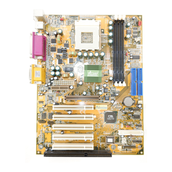
1.2 Motherboard Installation 1.2.1 Layout of Motherboard FAN3 USB1 CO M 1 Printer JACK1 JACK2 G A ME1 JACK3 AMR SLO T AG P SLO T FAN2 PCI1 PCI2 PCI3 PCI4 PCI5 FAN1 ISA SL O T 5 / Chapter 1 Motherboard Description 5 / Chapter 1 Motherboard Description 5 / Chapter 1 Motherboard Description 5 / Chapter 1 Motherboard Description... -
Page 9: Motherboard Connectors
1.3 Motherboard Connectors FAN3 USB1 C O M 1 Printer JACK1 JACK2 G A ME1 JACK3 AMR SLO T A G P SL O T FAN2 PCI1 PCI2 PCI3 PCI4 PCI5 FAN1 ISA SL O T 1.Back Pannel I/O Connectors 1.Back Pannel I/O Connectors 2.CD Audio-In Connector 2.CD Audio-In Connector... -
Page 10: Front Panel Connector(J1)
1.3.1 Front Panel Connector(J1) J1 PANEL Connector PW_LED PW_BN HD_LED SMI_LED SPEAK Speaker Connector (SPEAK E R) An offboard speaker can be installed onto the m o therboard as a m a nufacturing option.An offboard speaker can be connected to the m o therboard at the front pannel connector. -
Page 11: Floppy Disk Connector(Fdd1)
ATX Power Switch (PW_BN) The system power is controlled by a m o m e ntary switch connected to this lead. Pushing the button once will switch the syste m ON. The syste m power LED lights when the syste m ' s power is on . Power LED Lead (PW_LED) The system power LED lights when the system power is on. -
Page 12: Atx 20-Pin Power Connector(Pw1)
1.3.4 ATX 20-pin Po w e r Connector(PW1) This connector supports the power button on-board. Using the ATX power supply, functions such as Modem Ring Wake- Up and Soft Power Off are supported on this m o therboard . This power connector supports instant power-on functionality, which m e ans that the syste m will boot up instantly when the power connector is inserted on the board. -
Page 13: Back Panel Connectors
1.4 Back Pannel Connectors Parallel (Printer) Port MIDI/(G A ME) Port (15-pin Female) (25-pin Female) PS/2 Mouse SPEAKER C O M 1 PS/2 Keyboard (6-pin Female) Serial Port(9-pin Male) LINE IN 1.4.1 PS/2 Mouse /Keyboard CO N N. The m o therboard provides a standard PS/2 m o use / Keyboard m i ni DIN connector for attaching a PS/2 m o use. - Page 14 Front Two USB Connectors:USB2 FAN3 USB1 C O M 1 Printer JACK1 JACK2 G A ME1 JACK3 AMR SLO T A G P SL O T FAN2 PCI1 PCI2 PCI3 PCI4 PCI5 FAN1 ISA SL O T USB 2 G N D G N D G N D G N D...
-
Page 15: Serial And Parallel Interface Ports
1.5 Serial and Parallel Interface Ports This syste m co m e s equipped with two serial ports and one parpllel port. Both types of interface ports will be explained in this chapter. The Serial Interfaces:CO M 1/CO M 2 The serial interface port is som e tim e s refered to as an RS- 232 port or an asynchronous co m m u nication port. - Page 16 FAN3 USB1 C O M 1 Printer JACK1 JACK2 G A ME1 JACK3 AMR SLO T A G P SL O T FAN2 PCI1 PCI2 CO M 2 PCI3 PCI4 PCI5 FAN1 ISA SL O T Parallel Interface Port Unlike the serial ports, parallel interface port has been standardized and should not present any difficulty interfacing peripherals to your system .
-
Page 17: Cpu Installation
1.6 CPU Installation 1.6.1 CPU Installation Procedure:Socket 462 1.Pull the lever sideways away from the socket then raise the lever to a 90-degree angle. 2.Locate Pin 1 in the socket and look for the white dot or cut edge in the CPU. Match Pin 1 with the white dot/cut edge then insert the CPU. -
Page 18: Cpu Clock Setting(Sw1)
1.6.2 CPU Clock Selection:SW1 FAN3 USB1 CO M 1 Printer JACK1 JACK2 G A ME1 JACK3 (MHZ) (MHZ) AMR SL O T 33.33 AG P SLO T FAN2 PCI1 33.67 PCI2 34.00 PCI3 PCI4 34.33 PCI5 35.00 FAN1 ISA SL O T 35.67 36.33 36.67... -
Page 19: Jumper Setting
1.7 Jumper Setting A ju m p er has two or m o re pins that can be covered by a plastic ju m p er cap, allowing you to select different syste m options. FAN3 Connector FAN3 USB1 C O M 1 Printer JACK1 JACK2... -
Page 20: Wake-On-Modem Header(Wom1)
1.7.1 CPU/System Fan Connectors:Fan2 P i n P i n A s s i g n m e n t A s s i g n m e n t P i n P i n P i n A s s i g n m e n t A s s i g n m e n t A s s i g n m e n t 1 1 1 1 1... -
Page 21: Amr Code Select(Jp1)
1.7.4 AMR Code Function:JP1 P i n P i n A s s i g n m e n t A s s i g n m e n t P i n P i n P i n A s s i g n m e n t A s s i g n m e n t A s s i g n m e n t 1 - 2... -
Page 22: Dram Installation
1.8 DRAM Installation 1.8.1 DIMM DRAM Access Tim e :3.3V Unbuffered SDRAM/ PC66/ PC100 and PC133 Type required. DRAM Type:8MB,16MB,32MB,64MB,128MB,256MB ,512MBDIMM Module.(168 pin) Bank Memory module DIMM 1 16MB,32MB,64MB,128MB,256MB,512MB ( Bank 0-1 ) 168 pin,3.3v SDRAM DIMM 2 16MB,32MB,64MB,128MB,256MB,512MB ( Bank 2-3 ) 168 pin 3.3v,SDRAM DIMM 3 16MB,32MB,64MB,128MB,256MB,512MB... -
Page 23: Audio Subsystem
1.9 Audio Subsystem FAN3 USB1 C O M 1 Printer JACK1 JACK2 G A ME1 JACK3 AMR SLO T CDIN1 CDIN2 A G P SL O T FAN2 PCI1 PCI2 PCI3 PCI4 PCI5 FAN1 ISA SL O T 1.9.1 CD Audio-In Connectors:CDIN1/CDIN2 Assignment Pin CDIN1 CD-R... -
Page 24: Bios Setup
2. BIO S Setup Introduction This m a nual discussed Award Setup program built into the ROM BIOS. The Setup progra m allows user to m o dify the basic syste m configuration. This special infor m a tion is then stored in battery-backed RAM so that it retains the setup infor m a tion when the power is turned off. - Page 25 APM Support These AWARD BIOS supports Version 1.1 & 1 .2 of the Advanced Power Managem e nt(APM) specification.Power m a nagem e nt features are im p lem e nted via the System Managem e nt Interrupt(SMI). Sleep and Suspend power m a nagem e nt m o des are supported.
- Page 26 K e ystroke Function Up arrow Move to previous item Down arrow Move to next item Left arrow Move to the ite m on the left( m e nu bar) Right arrow Move to the ite m on the right( m e nu bar) Main Menu:Quit without saving changes Subm e nus:Exit Current page to the next higher level m e nu...
-
Page 27: Main Menu
2.1 Main Menu Once you enter AWARD BIOS CMOS Set up Utility, the Main Menu will appear on the screen. The Main Menu allows you to select fro m several setup function. Use the arrow keys to select am o ng the item s and press<Enter> to accept and enter the sub-m e nu. - Page 28 Advanced BI O S Features This setup page includes all the ite m of BIOS special enchanced features. Advanced Chipset Features This setup page includes all the ite m of Chipset special enchanced features. Integrated Peripherals This selection page includes all the ite m of IDE hard drive and Progra m m e d Input/Output features.
- Page 29 Load O p timized Defaults These settings are m o re likely to configure a workable com p uter when som e thing is wrong. If you cannot boot the com p uter seccessfully, select the BIOS Setup options and try to diagnose the problem after the com p uter boots.
-
Page 30: Standard Cmos Features
2.2 Standard CMO S Features This ite m in Standard CMOS Setup Menu is divided into 10 categories. Each category includes no, one or m o re than one setup item s . Use the arrow keys to highlight the item and then use the <PgUp>... - Page 31 Main Menu Selections This table shows the selections that you can m a ke on the Main Menu. Item O p tions Description Date Month DD YYYY Set the syste m , date.note that the ‘Day’ auto m a tically changes when you set the data.
- Page 32 Item O p tions Description Halt On All Errors Select the situation in which you No Errors want the BIOS to stop the POST All,but Keyboard process and notify. All,but Diskette All,but Disk/Key Base Me m o ry N/A Displays the am o unt of conventional m e m o ry detected during boot up.
-
Page 33: Advanced Bios Features
2.3 Advanced BI O S Features ◎ ◎ ◎ ◎ ◎ Figure 3. Advanced BI O S Features CMOS Setup Utility-Copyright(C) 1984-2000 Award Software advanced BIOS Features Anti-Virus Protection Disabled Item Help CPU Internal Cache Enabled External Cache Enabled Menu Level CPU L2 Cache ECC Checking Enabled Q u ick Power O n Self Test... - Page 34 CPU Internal Cache These two categories speed up m e m o ry access. However, it depends on CPU/chipset design. Enabled(default) Enabled cache. Disabled Disabled cache. External Cache This fields allow you to Enable or Disable the CPU’S “Level 2” secondary cache. Caching allows better perfor m a nce.
- Page 35 First/Secondary/Third/Boot O t her Device These BIOS atte m p ts to load the operating syste m fro m the devices in the sequence selected in these ite m s . The Choices:Floppy, LS120, HDD-0, HDD-1, HDD-2, HDD-3, SCSI, CDROM, Enabled, ZIP, LAN, Disabled. Swap Floppy Drive If the syste m has two floppy drives, you can swap the logical drive nam e assignm e nts.
- Page 36 Typematic Delay (Msec) This option sets the ti m e interval for displaying the first and the second characters. The Choices:250(default) ,500,750,1000 Security O p tion This category allows you to lim i t access to the system and Setup,or just to Setup. System The syste m will not boot and access to Setup will be defined...
-
Page 37: Advanced Chipset Features
2.4 Advanced Chipset Features This section allows you to configure the syste m based on the specific features of the installed chipset. This chipset m a nages bus speeds and access to system m e m o ry resources, such as DRAM and external cache. It also coordinates com m u nications the PCI bus. - Page 38 DRAM Timary by SPD The Choices:Enabled(default),Disabled DRAM Clock This ite m deter m i nes DRAM Clock following the CPU host clock,or . The Choices:100(default),133,66. SDRAM Cycle Length When synchronous DRAM is installed, the num b er of clock cycle of CAS latency depends on the DRAM ti m i ng. Do not reset this field from the default value specified by the system designer.
- Page 39 Video RAM Cacheable When enabled, the access to the syste m VGA RAM address is cached. The Choices:Diasbled(default),Enabled. A G P Aperture Size Select the size of the Accelerated Graphic Port(AGP) aperture. The aperture is a portion of the PCI m e m o ry address range dedicated for graphics m e m o ry address space.
- Page 40 USB K e yboard Support Select Enabled if your system contains a Universal Serial Bus(USB) controller and you have a USB keyboard. The Choices:Disabled(default),Enabled. O n chip Sound The default setting of this ite m unilizes an onboard sound chip for audio output. There is no need to buy and insert a sound card.
- Page 41 PCI #2 Access #1 Retry The Choices:Enabled(default),Disabled. A G P Master 1WS Write When Enabled,write to the AGP (Accelerated Graphic Port) are executed with one wait states. The Choices:Disabled(default),Enabled. A G P Master 1WS Read When Enabled,read to the AGP (Accelerated Graphic Port) are executed with one wait states.
-
Page 42: Integrated Peripherals
2.5 Integrated Peripherals ◎ ◎ ◎ ◎ ◎ Figure 5. Integrated Peripherals CMOS Setup Utility-Copyright(C) 1984-2000 Award Software Integrated Peripherals O n -Chip IDE Channel 0 Enabled Item Help O n -Chip IDE Channel 1 Enabled Primary Master PIO Auto Menu Level Primary Slave PI O Auto... - Page 43 O n -Chip IDE Channel 0 Enabled(default) Enabled onboard 1st channel IDE port. Disabled Disabled onboard 1st channel IDE port. O n -Chip IDE Channel 1 Enabled(default) Enabled onboard 2nd channel IDE port. Disabled Disabled onboard 2nd channel IDE port. Primary Master PIO ( for onboard IDE 1st channel) Auto(default) BIOS will autom a tically detect...
- Page 44 Primary Master UDMA Auto(default) BIOS will autom a tically detect the IDE HDD Accessing m o de. Disabled Disabled. Primary Slave UDMA Auto(default) BIOS will autom a tically detect the IDE HDD Accessing m o de. Disabled Disabled. Secondary Master UDMA Auto(default) BIOS will autom a tically detect the IDE HDD Accessing m o de.
- Page 45 UART 2 Mode This ite m allows you decide which Infra Red(IR) function of the onboard I/O chip,you wish to use. The Choices:Standard (default),SCR,ASKIR. IR Function Duplex This ite m allows you decide which Infra Red(IR) function of the onboard I/O chip. The Choices: H a lf (default),Full.
-
Page 46: Power Management Setup
2.6 Power Management Setup The Power Managem e nt Setup allows you to configure your system to m o st effectively save energy while operating in a m a nner consistent with your own style of co m p uter use. ◎... - Page 47 Power Management This option allows you to set each m o de individually. When not disabled, each of the ranges are from 1 m i n. to 1 hr. except for HDD Power Down which ranges from 1 m i n. to 15 m i n.
- Page 48 Video O f f O p tion This field deter m i nes when to activate the vedio off feature for m o nitor power m a nagem e nt. Video O f f Method This determ i nes the m a nner in which the m o nitor is blanked.
- Page 49 Wake Up Events If you highlight the literal “Press Enter” next to the “Wake Up Events” label and then press the enter key, it will take you a subm e nu with the following options: VG A When set to On,any event occurring at a VGA port will awaken a syste m which has been powered down.
- Page 50 Primary INTR When set to On(default),any event occurring at Pri m a ry INTR will awaken a system which has been powered down. The following is a list of IRQ, Interrupt ReQuests, which can be exe m p ted m u ch as the COM ports and LPT ports above can.
-
Page 51: Pnp/Pci Configurations
2.7 PnP/PCI Configurations This section describes configuring the PCI bus syste m . PCI or Personal Co m p uter Interconnect,is a syste m which allows I/O devices to operate at speeds nearing the speed of the CPU itself uses when co m m u nicating with its own special co m p onents. - Page 52 Reset Configuration Data The syste m BIOS supports the PnP feature so the syste m needs to record which resource is assigned and proceeds resources from conflict. Every peripheral device has a node, which is called ESCD. This node records which resources are assigned to it.
- Page 53 The above settings will be shown on the screen only if “Manual” is chosen for the resources controlled by function. Legacy is the ter m , which signifies that a resource is assigned to the ISA Bus and provides for non-PnP ISA add-on cards.
- Page 54 PCI / VG A Palette Snoop Choose Disabled or Enabled. Som e graphic controllers which are not VGA com p atible take the output from a VGA controller and m a p it to their display as a way to provide boot inform a tion and VGA com p atibility.
-
Page 55: Pc Health Status
2.8 PC H e alth Status ◎ ◎ ◎ ◎ ◎ Figure 8. PC H e alth Status CMOS Setup Utility-Copyright(C) 1984-2000 Award Software PC Health Status Current CPU Temp. Item Help Current System Temp. Current CPU Fan Speed Menu Level Current Sys Fan Speed Vcore A G P... -
Page 56: Frequency/Voltage Control
2.9 Frequency / Voltage Control ◎ ◎ ◎ ◎ ◎ Figure 9. Frequency / Voltage Control CMOS Setup Utility-Copyright(C) 1984-2000 Award Software Frequency / Voltage Control Auto Detect DIMM / PCI CLK Disabled Item Help Spread Spectrum Modulated Disabled Clock By Slight Adjust Menu Level ←→↑↓: Move Enter:Select... -
Page 57: Load Fail-Safe Defaults
2.10 Load Fail-Safe Defaults When you press <Enter> on this ite m , you get a confir m a tion dialog box with a m e ssage si m i lar to: ◎ ◎ ◎ ◎ ◎ Figure 10. Load Fail-Safe Defaults CMOS Setup Utility-Copyright(C) 1984-2000 Award Software STANDARD CMO S FEATURES... -
Page 58: Load Optimized Defaults
2.11 Load O p timized Defaults When you press <Enter> on this ite m , you get a confir m a tion dialog box with a m e ssage si m i lar to: ◎ ◎ ◎ ◎ ◎ Figure 11. Load O p timized Defaults CMOS Setup Utility-Copyright(C) 1984-2000 Award Software STANDARD CMO S FEATURES... -
Page 59: Set Supervisor/User Password
2.12 Set Supervisor / User Password ◎ ◎ ◎ ◎ ◎ Figure 12. Set Supervisor / User Password CMOS Setup Utility-Copyright(C) 1984-2000 Award Software STANDARD CMO S FEATURES FREQ U ENCY/CLO C K CO N TRO L ADVANCED BIO S FEATURES LO A D FAIL-SAFE DEFAULTS ADVANCED CHIPSET FEATURES L O A D O P TIMIZED DEFAULTS... - Page 60 Password Disabled If you select “Syste m ” at the Security Option of BIOS Features Setup Menu, you willbe prom p ted for the password every tim e when the system is rebooted, or any tim e when you try to enter Setup. If you select “Setup” at Security Option of BIOS Features Setup Menu, you willbe pro m p ted only when you try to enter Setup.
-
Page 61: Save & Exit Setup
2.13 Save & Exit Setup ◎ ◎ ◎ ◎ ◎ Figure 13. Save & Exit Setup CMOS Setup Utility-Copyright(C) 1984-2000 Award Software STANDARD CMO S FEATURES FREQ U ENCY/CLO C K CO N TRO L ADVANCED BIO S FEATURES LO A D FAIL-SAFE DEFAULTS ADVANCED CHIPSET FEATURES L O A D O P TIMIZED DEFAULTS INTEG R ATED PERIPHERALS... -
Page 62: Exit Without Saving
2.14 Exit Without Saving ◎ ◎ ◎ ◎ ◎ Figure 14. Exit Without Saving CMOS Setup Utility-Copyright(C) 1984-2000 Award Software STANDARD CMO S FEATURES FREQ U ENCY/CLO C K CO N TRO L ADVANCED BIO S FEATURES LO A D FAIL-SAFE DEFAULTS ADVANCED CHIPSET FEATURES LO A D O P TIMIZED DEFAULTS INTEG R ATED PERIPHERALS... - Page 63 Date : Warranty Card/Technical Fault Report M/B Model No.: Vender Serial No. Date of Purchasing: Hardw a re Configuration Used : RAM (Brand,MB ) Video Card Hard Drive O t her Card Diagnostic Soft w a re Used : Fault Description : 60 / Chapter 2 BIOS Setup 60 / Chapter 2 BIOS Setup 60 / Chapter 2 BIOS Setup...
- Page 64 The 7KTA/AP Mainboard layout FAN3 USB1 C O M 1 Printer JACK1 JACK2 G A ME1 JACK3 AMR SLO T A G P SL O T FAN2 PCI1 PCI2 PCI3 PCI4 PCI5 FAN1 ISA SL O T J1 PANEL Connector...
Need help?
Do you have a question about the 7KTA and is the answer not in the manual?
Questions and answers