Table of Contents
Advertisement
Contents
1. 7KT400 Specifications ........................ 4
1.1 Introduction ...................................................... 4
1.2 Package Contents ........................................... 5
1.3 Specifications and Features ............................ 6
CPU Processor ........................................................................... 6
Chipset ........................................................................................ 6
PCI ............................................................................................... 6
DDR SDRAM Memory ................................................................ 6
Universal Serial Bus ................................................................... 6
AGP ............................................................................................. 6
WOL (Wake On LAN) ................................................................... 6
Award BIOS ................................................................................. 7
ATA 133 On Board ........................................................................ 7
PC'99 Color-coded I/O Ports ...................................................... 7
Hardware Monitoring in Chip W83697HF .................................. 7
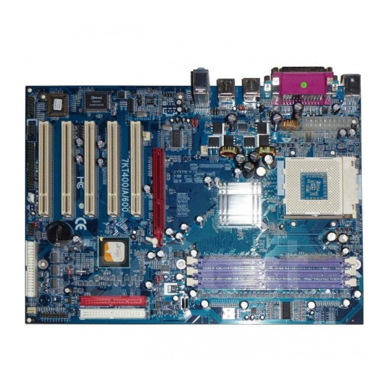
1.4 7KT400 Layout Diagram ................................. 8
1.5 CPU Installation ............................................. 10
CPU Installation Procedures for Socket 462 ............................ 10
1.6 DDR SDRAM Installation ............................... 11
1.7 Connectors & Jumpers Setting ...................... 12
1.7.1 Back Panel I/O Connectors .............................................. 12
1.7.1.1 PS/2 Mouse / Keyboard CONN: ....................................................................................... 12
1.7.1.2 USB0/1/2/3 ...................................................................................................................... 12
1.7.1.3 Serial Interface Port: COM1/2 .......................................................................................... 13
1.7.1.4 Parallel Interface Port ...................................................................................................... 13
1.7.1.5 Audio Ports ...................................................................................................................... 13
1.7.2 ATX Main Power Connectors: ATXPWR ............................ 14
1.7.3 Floppy Disk Connector: FDD ........................................... 15
1.7.4 Hard Disk Connectors: IDE1/IDE2 .................................. 15
1.7.5 Fan Connectors: FAN1/CPUFAN/SYSFAN ....................... 15
1.7.6 CD Audio-In Connectors: CDIN1 ..................................... 16
1.7.7 IR infrared module: IR/CIR Connector ............................ 16
1.7.8 USB Pin Header: USB4/5 ................................................ 17
1.7.9 Front Panel Connectors: PANEL1 .................................... 18
Motherboard 7KT400
0-1
Advertisement
Table of Contents

Related Manuals for Acorp 7KT400


Summary of Contents for Acorp 7KT400
-
Page 1: Table Of Contents
ATA 133 On Board ................ 7 PC’99 Color-coded I/O Ports ............7 Hardware Monitoring in Chip W83697HF ........7 1.4 7KT400 Layout Diagram ......... 8 1.5 CPU Installation ..........10 CPU Installation Procedures for Socket 462 ......10 1.6 DDR SDRAM Installation ....... 11 1.7 Connectors &... - Page 2 Contents Motherboard 7KT400 1.7.10 Wake On LAN Connector: WOL ........20 1.7.11 Game/MIDI Connector: J1 ..........20 1.7.12 Smart Panel Connectors (optional): ......21 1.7.12.1 Front COM2 Header Connector: COM2 ................. 21 1.7.12.2 Audio/Mic Auto Connector: JP1 ..................21 1.7.12.3 SPII Printer Error LED Port: SP-J6 ................. 22 1.7.12.4 Second BIOS Connector: SP-J2 ..................
- Page 3 Contents Motherboard 7KT400 Memo...
-
Page 4: Motherboard 7Kt400
Chapter 1 Motherboard 7KT400 1. 7KT400 Specifications 1.1 Introduction The 7KT400 motherboard is an integration of AMD Athlon/Duron CPU in Socket 462 packaging and the North Bridge VIA KT400 (VT8377) supporting 100/133/166 MHz Front Side Bus. North Bridge KT400 on board also supports DDR 200/... -
Page 5: Package Contents
Chapter 1 Motherboard 7KT400 1.2 Package Contents HDD UDMA66/100 Cable x1. FDD Cable. Flash Memory with BIOS. I/O Shielding Fully Setup Driver CD with built in utilities. User Manual. -
Page 6: Specifications And Features
Chapter 1 Motherboard 7KT400 1.3 Specifications and Features CPU Processor Support 100/133/166 MHz System Interface speed Single Socket 462 for AMD Athlon CPUs 700MHz~2700+ or higher*, and Duron CPUs 600 ~ 1300 MHz or higher* * The higher frequency CPU should be compatible with AMD CPU specificiation and the motherboard latest BIOS version which will be released in our Web Site (url printed on the cover page). -
Page 7: Award Bios
Chapter 1 Motherboard 7KT400 Award BIOS Supporting Plug & Play specification which detects the peripheral devices and expansion cards automatically Supporting CD-ROM, SCSI, LAN BOOT, Temperature sen- sor, LAN, Alarm Bus CLK setup Supporting Desktop Management Interface (DMI) func- tion for recording mainboard specification... -
Page 8: 7Kt400 Layout Diagram
Chapter 1 Motherboard 7KT400 1.4 7KT400 Layout Diagram KT400 AGP 8X Slot PCI 1 PCI 2 VT8235 PCI 3 PCI 4 BIOS PCI 5 Battery 13 14... - Page 9 Chapter 1 Motherboard 7KT400 7KT400 Component Layout : 1. Back Panel: Back Panel I/O Connectors ( Mouse, Keyboard, COM1, COM2, Printer, Mic in, Line in, Speaker-out, USB0/1/2/3) 2. J3: CPU clock Frequency Connector 3. CPUFAN1: CPU Fan Connector 4. CDIN1: CD Audio In Connector 5.
-
Page 10: Cpu Installation
Chapter 1 Motherboard 7KT400 1.5 CPU Installation The motherboard operates with Socket 462 for AMD Athlon and Duron processor. The CPU should always have a Heat Sink and cooling fan attached to prevent overheating. CPU Installation Procedures for Socket 462 1. -
Page 11: Ddr Sdram Installation
Chapter 1 Motherboard 7KT400 1.6 DDR SDRAM Installation The motherboard supports a maximized 3GB memory. It pro- vides three 184-pin unbuffered DDR sockets and each supports 64MB to 1GB DDR memory module. DDR SDRAM Installation Procedures: 1. The DDR socket has a “Plastic Safety Tab” and the DDR memory module has an asymmetrical notch”, so the DDR memory mod-... -
Page 12: Connectors & Jumpers Setting
Chapter 1 Motherboard 7KT400 1.7 Connectors & Jumpers Setting 1.7.1 Back Panel I/O Connectors This motherboard provides the following back panel connectors: Speaker Parallel(Printer) Port 25-pin female PS/2 Mouse USB0 USB1 COM2 Line-in PS/2 Keyboard COM1 USB2 (6-pin female) USB3 1.7.1.1 PS/2 Mouse / Keyboard CONN:... -
Page 13: Serial Interface Port: Com1/2
Chapter 1 Motherboard 7KT400 1.7.1.3 Serial Interface Port: COM1/2 The serial interface port is sometimes referred to as an RS- 232 port or an asynchronous communication port. Mice, printers, modems and other peripheral devices can be connected to a serial port. The serial port can also be used to connect computer systems together . -
Page 14: Atx Main Power Connectors: Atxpwr
Chapter 1 Motherboard 7KT400 1.7.2 ATX Main Power Connectors: ATXPWR This connector supports the power button on-board. Using the ATX power supply, functions such as Modem Ring Wake- Up and Soft Power Off are supported on this motherboard . T h i s p o w e r c o n n e c t o r s u p p o r t s i n s t an t p o w e r- o n functionality, which means that the system will boot up instantly when the power connector is inserted on the board. -
Page 15: Floppy Disk Connector: Fdd
Chapter 1 Motherboard 7KT400 1.7.3 Floppy Disk Connector: FDD This connector supports the provided floppy drive ribbon cable. After connecting the single end to the board, connect the two plugs on the other end to the floppy drives. 1.7.4 Hard Disk Connectors: IDE1/IDE2 These connectors are provided with IDE hard disk ribbon cable into the package . -
Page 16: Cd Audio-In Connectors: Cdin1
Chapter 1 Motherboard 7KT400 1.7.6 CD Audio-In Connectors: CDIN1 CDIN1 and CDIN2 are the connectors for CD-Audio Input signal. Please connect them to CD-ROM CD-Audio output connector. CDIN1 and CDIN2 have the same pin assignment but different pin pitch. Definition... -
Page 17: Usb Pin Header: Usb4/5
Chapter 1 Motherboard 7KT400 1.7.8 USB Pin Header: USB4/5 USB4/5 is 2x5 Pin Headers for support of external USB ports. Each USB pin header requires a USB cable for expansion of two USB ports. This optional USB cable is available from your motherboard dealer or vendor. -
Page 18: Front Panel Connectors: Panel1
Chapter 1 Motherboard 7KT400 1.7.9 Front Panel Connectors: PANEL1 Front Panel Connectors SMI LED KT400 EXTSMI HD LED (Void) VT8235 BIOS PS SW PSSW The system power is controlled by a momentary switch connected to this lead. Pushing the button once will switch the system ON. - Page 19 Chapter 1 Motherboard 7KT400 SMI Suspend Switch Lead This allows the user to manually place the system into the Suspend Green mode . System activity will be instantly decreased to save electricity and expand the life of certain components when the system is not in use. This 2-pin connector (see the figure) connects to the case-mounted suspend switch.
-
Page 20: Wake On Lan Connector: Wol
Chapter 1 Motherboard 7KT400 1.7.10 Wake On LAN Connector: WOL WOL connector is designed to connect to connect to PCI LAN card for waking up system by Ring signal sent in . KT400 Pin 1 5VSB Pin 2 GND VT8235... -
Page 21: Smart Panel Connectors (Optional)
Chapter 1 Motherboard 7KT400 1.7.12 Smart Panel Connectors (optional): SP-J6 KT400 VT8235 SP-J2 BIOS COM2 The motherboard provides the pin leads COM2, JP1, SP-J6 and SP-J2 for Smart Panel connection. If you want POST Error Code or Smart Panel function, please refer to Smart Panel manual. -
Page 22: Spii Printer Error Led Port: Sp-J6
Chapter 1 Motherboard 7KT400 1.7.12.3 SPII Printer Error LED Port: SP-J6 For Smart Panel connector ERR1 to M/B SP-J6. Assignment Assignment ERD4 ERD0 ERD5 ERD1 ERD6 ERD2 ERD7 ERD3 1.7.12.4 Second BIOS Connector: SP-J2 For Smart Panel connector SP-J2 to M/B SP-J2. -
Page 23: 6-Channel Sp-Dif Audio Connector: J6
Chapter 1 Motherboard 7KT400 1.7.12.5 6-channel SP-DIF Audio Connector: J6 J6 is designed to support the 6-channel SP-DIF Audio Connector, and this is an optional funtion. Assignment Assignment AVDD5V Center Lef-out SPDIFI GND-Aud SPDIFO Sur-out-L Sur-out-R 1-23... -
Page 24: Cmos Function Selector: Clear_Cmos
Chapter 1 Motherboard 7KT400 1.7.13 CMOS Function Selector: Clear_CMOS When you have problem with booting system, you may clear CMOS to restore the optimum default BIOS data. Jumper Clear CMOS 1-2 closed Normal (Default) KT400 2-3 closed Clear CMOS VT8235 BIOS 1. -
Page 25: Cpu Clock Frequency Selector: J3 & J5
Chapter 1 Motherboard 7KT400 1.7.15 CPU Clock Frequency Selector: J3 & J5 J3 & J5 are designed to detect the CPU Frequency on board. This motherboard support 133/166 MHz overclocking, while 100 MHz is default CPU clock. J3 Setting J5 Setting... -
Page 26: Ports Usb0/1, 2/3 Wake-Up Selector : J2
Chapter 1 Motherboard 7KT400 1.7.16 Ports USB0/1, 2/3 Wake-up Selector : J2 J2 is designed to select the USB1 wake up function of system from ACPI S3 Suspend Mode. J2: USB0/1,2/3 Wake-up Select 1-2 closed KT400 Enabled 2-3 closed Disabled... -
Page 27: Bios Setup
Chapter 2 7KT400 BIOS Setup Chapter 2 BIOS Setup 2. BIOS Setup 2.1 BIOS Support This chapter discusses the Award BIOS Setup program built in the ROM BIOS. The Setup program allows the user to modify the basic system configuration. The modification is then stored in battery-backed RAM so that it can retain the setup information after the power is turned off. -
Page 28: Setup Menu
Chapter 2 7KT400 BIOS Setup APM Support This AWARD BIOS supports Version 1.1&1.2 of the Advanced Power Management(APM) specification.Power management features are implemented via the System Management Interrupt(SMI). Sleep and Suspend power management modes are supported. Power to the hard disk drives and video monitors can be managed by this AWARD BIOS. - Page 29 Chapter 2 7KT400 BIOS Setup Keystroke Function Up arrow Move to previous item Down arrow Move to next item Left arrow Move to the item on the left(menu bar) Right arrow Move to the item on the right(menu bar) Main Menu: Quit without saving changes...
-
Page 30: Main Menu
Chapter 2 7KT400 BIOS Setup 2.2 Main Menu Once you enter AWARD BIOS CMOS Set up Utility, the Main Menu will appear on the screen and allows you to se- lect from several setup function. Use the arrow keys to se- lect the items and press<Enter>... - Page 31 Chapter 2 7KT400 BIOS Setup Standard CMOS Features This setup page includes all the items in standard compatible BIOS. Advanced BIOS Features This setup page includes all the items of the BIOS special enchanced features. Advanced Chipset Features This setup page includes all the items of the Chipset special enchanced features.
- Page 32 Chapter 2 7KT400 BIOS Setup Load Optimized Defaults These settings are for configuring a workable computer when something is wrong. If you cannot boot the computer successfully, select the BIOS Setup options and try to diagnose the problem after the computer boots. These settings do not provide optional performance.
-
Page 33: Standard Cmos Features
Chapter 2 7KT400 BIOS Setup 2.3 Standard CMOS Features This main option in the Standard CMOS Setup Menu is divided into 10 fields or items. Each field provides one or more setup choices. Use the arrow keys to highlight the field and then use the <PgUp>... - Page 34 Chapter 2 7KT400 BIOS Setup Main Menu Selections This table shows the selections that you can make on the Main Menu. Item Options Description Date Month Day Year Set the system,date. Note that the (mm : dd :yy) ‘Day’ automatically changes when you set the data.
- Page 35 Chapter 2 7KT400 BIOS Setup Item Options Description Halt On All Errors Select the situation in which you No Errors want the BIOS to stop the POST All, but Keyboard process and notify. All, but Diskette All, but Disk/Key Base Memory (640K) The amount of conventional mem- ory detected during boot up.
- Page 36 Chapter 2 7KT400 BIOS Setup IDE HDD Auto-Detection Press Enter on this item to let BIOS auto-detect your Hard Disk and show all the Primary Hard Disk Parameters ( Capacity, Cylinder, Head, Precomp, Landing Zone, Sector) on the menu. IDE Primary(Master/Slave) / Secondary(Master/Slave) This item allows you to detect the Hard Disk in 3 ways.
-
Page 37: Advanced Bios Features
Chapter 2 7KT400 BIOS Setup 2.4 Advanced BIOS Features Phoenix - AwardBIOS CMOS Setup Utility Advanced BIOS Features Virus Warning Disabled Item Help CPU Internal Cache Enabled External Cache Enabled Quick Power On Self Test Enabled First Boot Device Floopy... - Page 38 Chapter 2 7KT400 BIOS Setup CPU Internal / External Cache Allows you to Enable or Disable the CPU’s L1(Internal) / L2 (External) cache to provide better performance. The choices: Enabled(default); Disabled Quick Power On Self Test This category speeds up Power on self-Test(POST) after you power up the computer.
- Page 39 Chapter 2 7KT400 BIOS Setup Boot Up Floppy Seek If enabled, this item allows BIOS to test floppy drives to determine whether they have 40 or 80 tracks. The Choices: Disabled(default), Enabled. Boot Up NumLock Status Select power on state for Numlock..
- Page 40 Chapter 2 7KT400 BIOS Setup Security Option This category allows you to determine whether to use password access the system and Setup,or just Setup. The choices: System: To access system and BIOS Setup with correct password. Setup (default): To access BIOS Setup with correct password.
-
Page 41: Advanced Chipset Features
Chapter 2 7KT400 BIOS Setup 2.5 Advanced Chipset Features This section allows you to configure the system based features of the installed chipset. This chipset manages bus speeds and access to system memory resources, such as DRAM and external cache. It also coordinates communica- tions of the PCI bus. -
Page 42: Dram Clock
Chapter 2 7KT400 BIOS Setup DRAM Clock/Drive Control Press Enter on this item to open the Sub-menu as shown below: Phoenix - AwardBIOS CMOS Setup Utility DRAM Clock/Drive Control Item Help Current FSB Frequency 100MHz Current DRAM Frequency 100MHz DRAM Clock... - Page 43 Chapter 2 7KT400 BIOS Setup x DRAM CAS Latency When DRAM Timing is set Manual, use this item to set the DRAM CAS Latency tine. . The Choices: 1.5; 2; 2.5; 3 x Bank Interleave When DRAM Timing is set Manual, use this item to set the DRAM Bank Interleave.
- Page 44 Chapter 2 7KT400 BIOS Setup Write Recovery Time Use this item to set the Write Recovery Time. The Choices: 3T; 2T DRAM twTR Use this item to set the DRAM twTR time. The Choices: 3T; 1T DRAM Access Use this item to set the DRAM Access time..
-
Page 45: Agp Driving Control
Chapter 2 7KT400 BIOS Setup AGP P2P Bridge Control Press Enter on this item to open the Sub-menu as shown below: Phoenix - AwardBIOS CMOS Setup Utility AGP P2P Bridge Control Item Help AGP Aperture Size 128M AGP Mode AGP Driving Control... - Page 46 Chapter 2 7KT400 BIOS Setup x AGP Driving Value When AGP Driving Control is set manual, use this item to set the AGP Driving address value. The Choices: 00 ~ FF in 1h stepping AGP Fast Write This item is to enable / disable the AGP Fast Write function.
- Page 47 Chapter 2 7KT400 BIOS Setup CPU & PCI Bus Control Press Enter on this item to open the Sub-menu as shown below: Phoenix - AwardBIOS CMOS Setup Utility CPU & PCI Bus Control Item Help PCI1 Master 0 WS Write...
- Page 48 Chapter 2 7KT400 BIOS Setup Memory Hole Use this item to enable or disable the Memory Hole. The Choices: Disabled; 15M ~ 16M System BIOS Cacheable Use this item to enable / disable the System BIOS Cacheable function. The choices: Enabled; Disabled...
-
Page 49: Integrated Peripherals
Chapter 2 7KT400 BIOS Setup 2.6 Integrated Peripherals Phoenix - AwardBIOS CMOS Setup Utility Integrated Peripherals Item Help USB 2.0 Support Enabled VIA Onchip IDE Device Press Enter VIA Onchip PCI Device Press Enter Super IO Device Press Enter Init Display First... -
Page 50: Via Onchip Ide Device
Chapter 2 7KT400 BIOS Setup USB 2.0 Support Use this item to enable or disable the USB 2.0 support. The Choices: Enabled (default); Disabled VIA OnChip IDE Device Press Enter on this item to open the Sub-menu as shown below:... - Page 51 Chapter 2 7KT400 BIOS Setup Primary Master/Slave PIO If OnChip IDE Channel is enabled, this item is to select the IDE Primary Master/Slave PIO mode (Programmed Input Output Mode). Mode4 is the fastest mode. The choices: Auto; Mode0; Mode1; Mode2; Mode3; Mode4...
-
Page 52: Via Onchip Pci Device
Chapter 2 7KT400 BIOS Setup VIA OnChip PCI Device Press Enter on this item to open the Sub-menu as shown below: Phoenix - AwardBIOS CMOS Setup Utility VIA OnChip PCI Device Item Help VIA-3058 AC97 Audio Auto VIA-3068 MC97 Modem Auto ←→↑↓: Move Enter:Select +/-/PU/PD:Value F10:Save ESC:Exit F1:General Help... -
Page 53: Super Io Device
Chapter 2 7KT400 BIOS Setup Super IO Device Press Enter on this item to open the Sub-menu as shown below: Phoenix - AwardBIOS CMOS Setup Utility VIA OnChip IDE Device Item Help Onboard FDC Controller Enabled Onboard Serial Port 1... - Page 54 Chapter 2 7KT400 BIOS Setup UART Mode Select This item allows you to select which Infra Red(IR) function of the onboard I/O chip you wish to use. The Choices: Normal(default), IrDA, ASKIR. RxD’ TxD Active This item allows you to select the high /Low status of the RxD, TxD Active mode.
- Page 55 Chapter 2 7KT400 BIOS Setup EPP Mode Select The Choices: EPP1.7; EPP1.9 ECP Mode Use DMA The Choices: 3, 1. Game Port Address The choices are for setting Game Port Address: 201 (default); 209; Disabled MIDI Port Address The choices are for setting MIDI Port Address: 290:300;...
-
Page 56: Power Management Setup
Chapter 2 7KT400 BIOS Setup 2.7 Power Management Setup Phoenix - AwardBIOS CMOS Setup Utility Power Management Setup ACPI Function Enabled Item Help ACPI Suspend Type S1(POS) Power Management Option User Define HDD Power Down Disabled Suspend Mode Disabled Video Off Option Suspend ->... - Page 57 Chapter 2 7KT400 BIOS Setup HDD Power Down The Choices are for enabling or disabling the HDD Power Down function. Disabled(default); 1Min~15 Min in 1 minute stepping Suspend Mode The Choices are for setting the length of suspend: Disabled(default); 1Min~1hour.
- Page 58 Chapter 2 7KT400 BIOS Setup IRQ/Event Activity Detect Press Enter on this item to open the Sub-menu as shown below: Phoenix - AwardBIOS CMOS Setup Utility VIA OnChip IDE Device Item Help PS2KB Wakeup Select Hot Key PS2KB Wakeup From S3/S4/S5...
- Page 59 Chapter 2 7KT400 BIOS Setup USB Resume from S1-S3 Use this item to enable / disable the USB resume from S3 (Suspend To RAM) function. The Choices: Enabled; Disabled Use this item to turn On or off the VGA. The Choices: On; Off LPT &...
-
Page 60: Irqs Activity Monitoring
Chapter 2 7KT400 BIOS Setup IRQs Activity Monitoring Press Enter on this item to open the Sub-menu as shown below: Phoenix - AwardBIOS CMOS Setup Utility VIA OnChip IDE Device Item Help Primary INTR IRQ3 (COM 2) Disabled IRQ4 (COM 1) - Page 61 Chapter 2 7KT400 BIOS Setup IRQ7 (LPT1) Use this item to enable / disable the IRQ7 for Floppy Disk. The choices: Enabled; Disabled IRQ8 (RTC Alarm) Use this item to enable / disable the IRQ8 for RTC Alarm. The choices: Enabled; Disabled IRQ9 (IRQ2 Redir) Use this item to enable / disable the IRQ2 redirect.
-
Page 62: Pnp/Pci Configurations
Chapter 2 7KT400 BIOS Setup 2.8 PnP/PCI Configurations This section describes configuration of the PCI bus system. PCI or Personal Computer Interconnect, is a system which allows I/O devices to operate at speeds nearing the speed of the CPU itself when communicating with the com- ponents on board. - Page 63 Chapter 2 7KT400 BIOS Setup Reset Configuration Data The system BIOS supports the PnP feature so the system needs to record which resource is assigned and proceeds to get rid of resource conflict. Every peripheral device has a node, which is called ESCD (Extended System Configuration Data.
- Page 64 Chapter 2 7KT400 BIOS Setup IRQ Resources When resources are controlled manually, assign each system interrupt a type, depending on the type of device using the interrupt. PCI / VGA Palette Snoop Choose Disabled or Enabled. Some graphic controllers which...
-
Page 65: Pc Health Status
Chapter 2 7KT400 BIOS Setup 2.9 PC Health Status Phoenix - AwardBIOS CMOS Setup Utility PC Health Status Item Help CPU Warning Temperature Disabled System Temperature CPU Temperature FAN 1 Speed FAN 2 Speed Vcore Vcc 3.3V Vcc 5.0V Vcc 12.V Vbat Vsb 5.0V... -
Page 66: Frequency/Voltage Control
Chapter 2 7KT400 BIOS Setup 2.10 Frequency/Voltage Control Phoenix - AwardBIOS CMOS Setup Utility Frequency/Voltage Control Item Help Auto Detect DIMM/PCI Clk Enabled Spread Spectrum Disabled CPU Clock 100MHz Auto Detect PCI CLK Ensabled ←→↑↓: Move Enter:Select +/-/PU/PD:Value F10:Save ESC:Exit F1:General Help... -
Page 67: Load Fail-Safe Defaults
Chapter 2 7KT400 BIOS Setup 2.11 Load Fail-Safe Defaults When you press <Enter> on this item, you get a confirmation dialog box with a message similar to below: Phoenix - AwardBIOS CMOS Setup Utility Frequency/Voltage Control Standard CMOS Features Load Fail-safe Defaults... -
Page 68: Load Optimized Defaults
Chapter 2 7KT400 BIOS Setup 2.12 Load Optimized Defaults When you press <Enter> on this item, you get a confirmation dialog box with a message similar to: Phoenix - AwardBIOS CMOS Setup Utility Frequency/Voltage Control Standard CMOS Features Load Fail-safe Defaults... -
Page 69: Set Supervisor / User Password
Chapter 2 7KT400 BIOS Setup 2.13 Set Supervisor / User Password Phoenix - AwardBIOS CMOS Setup Utility Frequency/Voltage Control Standard CMOS Features Load Fail-safe Defaults Advanced BIOS Features Load Optimized Defaults Advanced Chipset Features Set Supervisor Password Integrated Peripherals Set User Password... -
Page 70: Save & Exit Setup
Chapter 2 7KT400 BIOS Setup 2.14 Save & Exit Setup Phoenix - AwardBIOS CMOS Setup Utility Frequency/Voltage Control Standard CMOS Features Load Fail-safe Defaults Advanced BIOS Features Load Optimized Defaults Advanced Chipset Features Save to CMOS & Exit (Y/N)? Y... -
Page 71: Exit Without Saving
Chapter 2 7KT400 BIOS Setup 2.15 Exit Without Saving Phoenix - AwardBIOS CMOS Setup Utility Frequency/Voltage Control Standard CMOS Features Load Fail-safe Defaults Advanced BIOS Features Load Optimized Defaults Advanced Chipset Features Set Supervisor Password Integrated Peripherals Quit Without Saving (Y/N)? N... -
Page 72: Drivers & Utilities
Chapter 3 7KT400 Drivers & Utilities Chapter 3 Drivers & Utilities 3. Drivers & Utilities There are motherboard drivers and utilities included in the disc attached in this motherboard package. You don't have to install all of them for booting your system. But after... -
Page 73: Installing Via Service Pack
Chapter 3 7KT400 Drivers & Utilities 3.2 Installing VIA Service Pack Enter the item "Chipset" of the Autorun program and install the VIA Service Pack. Follow the illustrations below : Click "Driver" Item. Click "Chipset" Item. Click "VIA service Pack"... - Page 74 Chapter 3 7KT400 Drivers & Utilities Click "Next". Click "Yes". Tick all four items and click "Next". 3-74...
- Page 75 Chapter 3 7KT400 Drivers & Utilities The Setup Program will install all items until the Restart screen appears. Click "OK" to restart system. 3-75...
-
Page 76: Installing Audio Driver
Chapter 3 7KT400 Drivers & Utilities 3.3 Installing Audio Driver This motherboard comes with an AC97 CODEC V2.2, 6-chan- nel compatible. You can find the Audio driver from this Auto-run menu. Click "Driver" Item. Click "Audio" Item. Click "ALC650" Item. - Page 77 Chapter 3 7KT400 Drivers & Utilities Click "Next". Click "Finish". 3-77...
-
Page 78: Installing Usb 2.0 Driver
Chapter 3 7KT400 Drivers & Utilities 3.4 Installing USB 2.0 Driver Click the "Driver " item. Click the "USB " item. Click the "USB2.0 " item. 3-78... - Page 79 Chapter 3 7KT400 Drivers & Utilities Click the "Next " item. Tick "Install USB Driver" and click the "Next " item. Click the "Finish " item to restart system. 3-79...
-
Page 80: Appendices
Appendices Appendices Appendix I Quick Jumper Setup J3 Setting J5 Setting 100 MHz CPU(MHz) 133 MHz 166 MHz (default) J2: USB0/1, 2/3 Wake-up Selector 1-2 closed Enabled KT400 2-3 closed Disabled(Default) VT8235 BIOS Jumper Clear CMOS JP4: USB4/5 Wake-up Selector Normal Enabled closed... - Page 81 Appendices Test Report 4-81...
- Page 82 Appendices 4-82...
- Page 83 Appendices 4-83...
- Page 84 Appendices 4-84...
Need help?
Do you have a question about the 7KT400 and is the answer not in the manual?
Questions and answers