Table of Contents
Advertisement
Quick Links
7VIA71A
User's Manual Version 1.1
The information presented in this publication has been
made carefully for reliability; however, no responsibility
is assumed for inaccuracies. Specifications are subject
to change without notice.
IBM, PC/AT, and PC/XT are trademarks of Interna-
tional Business Machines Corporation.
Slot-A is a trademark of AMD Corporation
AWARD is a registered trademark of Award
Sofftware Inc.
MS-DOS and WINDOWS NT are registered trade-
marks of Microsoft Corporation.
Trademarks and/or registered trademarks are the
properties of their respective owners.
Advertisement
Table of Contents

Subscribe to Our Youtube Channel
Related Manuals for Acorp 7VIA71A


Summary of Contents for Acorp 7VIA71A
- Page 1 7VIA71A User's Manual Version 1.1 The information presented in this publication has been made carefully for reliability; however, no responsibility is assumed for inaccuracies. Specifications are subject to change without notice. IBM, PC/AT, and PC/XT are trademarks of Interna- tional Business Machines Corporation.
-
Page 2: Table Of Contents
Table of Contents Chapter 1 Introduction ..........1 How this manual is organized ......1 Package checklist ..........2 Chapter 2 Features ............3 Features of the mainboard ......3 The mainboard layout ....... 6 Chapter 3 Installation ..........7 System Installation Setups ...... -
Page 3: Chapter 1 Introduction
C h apter 1 Introduction Ho w This Manual is O r ganized This m a nual is divided into the following sections: Chapter 1 Introduction : Manual inform a tion and checklist. Chapter 2 Features : Infor m a tion and Specifications con- cerning this m a inboard. -
Page 4: Package Checklist
Please check that your package is com p lete . If you discover any item dam a ged or m i ssing , please contact with your retailer im m e diately. The 7VIA71A m a inboard. Retention Mechanis m & Heat Sink Support. -
Page 5: Chapter 2 Features
C h apter 2 Features Features of the 7VIA71A Mainboard The 7VIA71A is designed for the PC user’s who want m a ny new key features processed by the fastest CPU in a econom i c package. This m a inboard : New general CPU support : AMD K7 SLOT-A (500 MHz-1GHz Athlon) processor. - Page 6 VIA K X 133 chips with I/O subsystem s . Biggest memory capacity : 7VIA71A is equipped with two DIMM socket to support (16MB, 32MB, 64MB, 128MB.256MB) 168 pin 3.3v SDRAM SPD(Special Presence Detect).Maxim u m m e m o ry up to 512MB.
- Page 7 CPU built-in Level 2 Cache : The AMD Athlon includes the largest L1 cache (128K total) for x86 platfor m s . The AMD Athlon also features a high- speed, 64-bit backside L2 cache controller that supports L2 cache sizes ranging from 512K to a m a ssive 8MB. This high- perform a nce cache design takes advantage of the processor's high-speed system bus and m i nim i zes bandwidth bottlenecks.
-
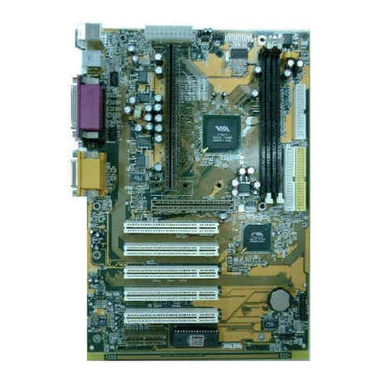
Page 8: The Mainboard Layout
The 7VIA71A Mainboard layout MIDI/ G A ME/ AUDIO 6 / Chapter 2 Features 6 / Chapter 2 Features 6 / Chapter 2 Features 6 / Chapter 2 Features 6 / Chapter 2 Features... -
Page 9: Chapter 3 Installation
C h apter 3 Installation Jumper Jumper Refer to page - CPU bus frequency selection JBAT - Real ti m e Clock RTC clean FAN1 - FAN CONN. for CPU FAN2 - FAN CONN. for AGP FAN3 - FAN CONN. for CPU - Wake ON LAN Function - Wake On Modem Function 7 / Chapter 3 Installation... - Page 10 Expansion Slot Which page SEC(Single Edge Connector) CPU Slot-A 168 pin DIMM Socket AGP (Accelerated Graphic port) SLOT PCI SLOT 1,2,3,4,5 -32bits PCI SLOT Connectors Refer to page PS2_KB - PS/2 Mouse port(UP). PS2_KB - PS/2 AT( m i ni DIM) Keyboard port(DP)25 COM1 - COM 1 serial port COM2...
-
Page 11: System Installation Setups
System Installation Setup Before using your com p uter, you m u st finish the following steps: 1. Set ju m p ers on m a inboard. 2. Install SDRAM m o dule. 3. Install the Athlon Processor. 4. Connect Ribbon Cables, Cabinet Wires, and Power supply. 5. -
Page 12: Jumper Settings
Jumper Settings Jumpers Several hardware setting are m a de through the use of jum p er caps to connect jum p er pins (Jxx) on the m a inboard. See " Map of the m a inboard" for locations of jum p ers. The ju m p er settings will be described nu m e rically such as [----], [1-2], [2-3] for no connection, connect pins 1 &... - Page 13 Real Time Clock (RTC) RAM - JBAT : The CMOS RAM is powered by the onboard button cell battery. To clear the RTC data: (1)Turn off your co m p uter, (2) Move this ju m p er to "2-3Pin Clear Data", (3) Move the ju m p er back to "Default", (4) Turn on your com p uter, (5) Hold down <Delete >...
- Page 14 CPU External (Bus) Frequency Selection - JP1 These ju m p ers tell the clock generator what frequency to send to the CPU. These allow the selection of the CPUs External Frequency (or Bus Clock). The Bus Clock ti m e s the BUS ratio equals the CPUs Internal Frequency (the advertised CPU speed).
- Page 15 (MHZ) (MHZ) 33.3 34.0 34.6 35.3 35.6 36.0 36.3 36.6 37.0 37.3 33.3 STR Function(Suspend to RAM )-J3 J 3 S T R F u n c t i o n J 3 S T R F u n c t i o n J 3 S T R F u n c t i o n J 3 S T R F u n c t i o n J 3 S T R F u n c t i o n...
-
Page 16: System Memory (Dimm Modules)
System Memory ( DIMM Module) This 7VIA71A m a in board supports two 168 pin DIMM ( Dual Inline Mem o ry Module) of 16 MB, 32 MB, 64 MB, 128 MB ,256MB to form a m e m o ry size between 16MB to 256MB. -
Page 17: Dimm Memory Installation
DIMM Memory Installation Insert the m o dule (s) as shown. Because the num b er pins are differ- ent on either side of the breaks,the m o dule will only fit in the orienta- tion as shown. SDRAM DIMM m o dules have different pin contacts on each side and therefore have a higher pin density. - Page 18 The Dual Inline Me m o ry Module (DIMM) m e m o ry m o dule m u st be 3. 3v Extended Data Output (EDO) DRAM or SDRAM. You can identify the type of DIMM m o dule by the illustration below: Unbuffered 5.0V Reserved...
-
Page 19: Central Processing Unit (Cpu)
Central Processing Unit (CPU) This m a in board provides a Single Edge Contact (SEC) slot for AMD Athlon processor packaged in an SEC cartridge. The SEC slot is not co m p atible with other non-Athlon Processors. Installing the Retention Mechanism The Mainboard package includes a Retention Mechanis m . - Page 20 Captive nut Hole Installing Boxed Processor 1. Mount the two black plastic pegs onto the system board. /these pegs will be used to attach the fan heatsink supports. Notice that one hole and the base of one peg are larger than the other hole and peg base.
- Page 21 3. Slide the clip (A) as shown on each support toward the processor, exposing the hole that will fit over the peg on the m a inboard . Push the latches (B) on the processor toward the center of the processor until they click into place.
-
Page 22: Removing The Processor
Removing the Processor To Re m o ve the processor fro m the syste m board,follow these steps (the reverse of the installation processor) : 1. Disconnect the fan power cable from the m a in board. (We rec- om m e nd that you leave the cable connected to the processor) . 2. -
Page 23: Installing Oem Processor
Installing O E M Processor If you are using AMD Athlon Processor in OEM package, Please follow the steps below: 1. Your OEM package m a y include the following ite m s : Note : Make sure your heatsink is attached with a fan to prevent overheating the processor. - Page 24 4. Install the HSS Base by pushing each side down fir m l y into the holes on the m a inboard. (HSS Base can only be installed in one direction). Make sure it locks into place. 5. Replace the HSS Pins on each end of the HSS Base. These pins will insert through the HSS Base to secure it to the m a inboard.
-
Page 25: Clearance Requirements
10.Attach the s m a ll end of the power cable to three-pin connector in the processor, then attach the large the large end to the three- pin connector on the m a in board. Clearance Requirements To m a intain proper airflow once the processor is installed on the m a inboard, the processor and fan heatsink require certain space clearances. -
Page 26: External Connectors
EXTERNAL C O N NECT O R S Both Ribbon cable and Connectors on board are with direction signs to avoid that user insert wrong direction. On other hand, the ribbon cables should always be connected with the red stripe on the pin 1 of side of the connector. - Page 27 1. PS/2 Mouse port This system will direct IRQ12 to PS/2 m o use. 2. PS/2 AT K e yboard port This connection is for a standard keyboard using an PS/2 plug (m i ni DIN) . This connector will not allow standard at AT size (large DIN) keyboard plugs.
- Page 28 7. FAN1 , 2,3 CPU Cooling Fan (FAN/PWR) These connectors support cooling fans of 500 m A m p (6Watt) or less. Orientate the fans so that the heatsink fins allow airflow to go across the onboard heat sink(s) instead of the expansion slots. Depending on the fan m a nufacturer, the wiring and plug m a y be different.
- Page 29 8. Primary / Secondary IDE connectors (Two 40-pin Blocks) These connectors support the provided IDE hard disk ribbon cable. After connecting the single end to the board, connect the two plugs at the other end to your hard disk no space(s) . If you install two hard disks, you m u st configure the second drive to Slave m o de by setting its ju m p er setting.
- Page 30 9. IrDA / Fast IR-Compliant infrared module connector - IR This connector supports the optional wireless transm i tting and receiving infrared m o dule. This m o dule m o unts to a sm a ll open- ing on system cases that support this feature. You m u st also configure the setting through UART2 Use Infrared”...
- Page 31 10.PANEL1 (J4) PANEL1 (J4) PANEL Connector PW_LED PW_BN HD_LED SPEAK a. IDE activity LED (H D _LED) This connector supplies power to the cabinet’s IDE activity LED. Read and write activity by devices connected to the Prim a ry or Secondary IDE connectors will cause the LED to light up.
- Page 32 e. Speaker Connector (SPEAK E R) This 4-pin connector connects to the case-m o unted speaker. f.ATX Power Switch (PW_BN) The system power is controlled by a m o m e ntary switch con- nected to this lead. Pushing the button once will switch the sys- te m ON.
-
Page 33: Wake Up On Lan
12. CD Audio Connector- CD_IN/CD_IN1 The 4-pin connectors enable the system to receive the audio output from the CD-ROM. CD_IN Description CD-R G N D CD-L G N D CD_IN1 Description CD-R G N D G N D MIDI/ CD-L G A ME/ AUDIO Wake-O n -LAN Connector... - Page 34 O t her Card Diagnostic Soft w a re Used : Fault Description : Technical Support : WWW : w w w . acorp.com.t w fae@acorp.com.tw 32 / Chapter 3 Installation 32 / Chapter 3 Installation 32 / Chapter 3 Installation...
Need help?
Do you have a question about the 7VIA71A and is the answer not in the manual?
Questions and answers