Allied Telesis AT-TQ4600 Installation Manual
Enterprise-class wireless access point
with ieee802.11a/b/g/n/ac dual radio
Hide thumbs
Also See for AT-TQ4600:
- Quick installation manual (2 pages) ,
- Installation manual (58 pages) ,
- Installation manual (72 pages)

Related Manuals for Allied Telesis AT-TQ4600


Summary of Contents for Allied Telesis AT-TQ4600
-
Page 1: Installation Guide
AT-TQ4600 Enterprise-class Wireless Access Point with IEEE802.11a/b/g/n/ac Dual Radio Installation Guide 613-002009 Rev. C... - Page 2 Allied Telesis, Inc. has been advised of, known, or should have known, the...
-
Page 3: Electrical Safety And Emissions Standards
This product meets the following standards: Federal Communications Commission Interference Statement Declaration of Conformity Manufacturer Name: Allied Telesis, Inc. Declares that the product: Wireless access point with PoE+ powered device function Model Number: AT-TQ4600 This device complies with Part 15 of the FCC Rules. Operation is subject to the following two conditions: (1) This device may not cause harmful interference, and (2) this device must accept any interference received, including interference that may cause undesired operation. - Page 4 European Union Restriction of the Use of Certain Hazardous Substances (RoHS) in Electrical and Electronic Equipment This Allied Telesis RoHS-compliant product conforms to the European Union Restriction of the Use of Certain Hazardous Substances (RoHS) in Electrical and Electronic Equipment. Allied Telesis ensures RoHS conformance by requiring supplier Declarations of Conformity, monitoring incoming materials, and maintaining manufacturing process controls.
- Page 5 Electromagnetic Compatibility (EMC) EN 301 489-1 EN 301 489-17 EN 55022 EN 55024 EN 61000-3-2 EN 61000-3-3 EN 61000-4-2 EN 61000-4-3 EN 61000-4-4 EN 61000-4-5 EN 61000-4-6 EN 61000-4-11 ...
-
Page 6: Translated Safety Statements
Translated Safety Statements Important: The indicates that a translation of the safety statement is available in a PDF document titled Translated Safety Statements on the Allied Telesis website at www.alliedtelesis.com/support. -
Page 7: Table Of Contents
Reset Button .............................. 24 Chapter 2: Installing the Access Point ......................25 Reviewing Safety Precautions ........................26 Unpacking the AT-TQ4600 Access Point....................28 Installing the Access Point on a Wall or Ceiling ..................29 Guidelines............................29 Mounting the Base Plate to the Wall or Ceiling ................... 30 Attaching the Mounting Bracket to the Access Point................ - Page 8 Contents...
- Page 9 Figures Figure 1: Rear Panel Components ........................19 Figure 2: AT-TQ0091 AC/DC Power Adapter....................28 Figure 3: Ventilation Slots..........................29 Figure 4: Base Plate Hole Dimensions......................30 Figure 5: Mounting Base Plate ........................30 Figure 6: Bottom of Access Point ........................31 Figure 7: Locking Bracket to Access Point ......................
- Page 10 List of Figures...
- Page 11 Table 1. Components on the Rear Panel ....................... 19 Table 2. Twisted Pair Cable for the LAN Port ....................22 Table 3. LEDs on the AT-TQ4600 Access Point .................... 23 Table 4. AT-TQ4600 Physical Specifications ....................43 Table 5. Environmental Specifications ......................43 Table 6.
- Page 12 List of Tables...
-
Page 13: Preface
Preface This guide contains the hardware installation instructions for the AT-TQ4600 Wireless Access Point. This preface contains the following sections: “Safety Symbols Used in this Document” on page 14 “Contacting Allied Telesis” on page 15... -
Page 14: Safety Symbols Used In This Document
Preface Safety Symbols Used in this Document This document uses the following conventions. Note Notes provide additional information. Caution Cautions inform you that performing or omitting a specific action may result in equipment damage or loss of data. Warning Warnings inform you that performing or omitting a specific action may result in bodily injury. -
Page 15: Contacting Allied Telesis
AT-TQ4600 Wireless Access Point Installation Guide Contacting Allied Telesis If you need assistance with this product, you may contact Allied Telesis technical support by going to the Support & Services section of the Allied Telesis web site at www.alliedtelesis.com/support. You can find links for the following services on this page: ... - Page 16 Preface...
-
Page 17: Chapter 1: Overview
Chapter 1 Overview This chapter describes the hardware components of the AT-TQ4600 Wireless Access Point. This chapter contains the following sections: “Features” on page 18 “Rear Panel Components” on page 19 “LAN Port” on page 21 ... -
Page 18: Features
Chapter 1: Overview Features The main features of the product are listed here: Dual radio: 2.4 GHz and 5 GHz IEEE 802.11a/b/g/n/ac 3x3:3ss MIMO with internal omni antennas Maximum capacity 2.4 GHz: 450 Mbps Maximum capacity 5 GHz: 1300 Mbps ... -
Page 19: Rear Panel Components
AT-TQ4600 Wireless Access Point Installation Guide Rear Panel Components The rear panel components of the AT-TQ4600 Access Point are illustrated in Figure 1. Kensington Reset LAN Port Lock Button DC Power Console Connector Port Figure 1. Rear Panel Components The components are listed in Table 1. - Page 20 This connector is for the AT-TQ0091 Power Adapter. The access point can be powered with PoE+ on the LAN port or the power adapter. The AT-TQ0091 Power Adapter does not come with the access point. It must be ordered separately from Allied Telesis.
-
Page 21: Lan Port
The LAN port is used to connect the device to your Local Area Network (LAN), typically through an Ethernet switch. Power over The AT-TQ4600 Access Point supports Power over Ethernet (PoE+) on the LAN port. The unit is a PoE+ class 4 powered device with a maximum Ethernet power consumption of 16 watts. -
Page 22: Automatic Mdix Detection
Chapter 1: Overview Table 2. Twisted Pair Cable for the LAN Port 10Mbps 100Mbps 1000Mbps Cable Type Non- Non- Non- PoE+ PoE+ PoE+ PoE+ PoE+ PoE+ Standard TIA/EIA 568- B-compliant Category 3 shielded or unshielded cabling with 100 ohm impedance and 16 MHz frequency. -
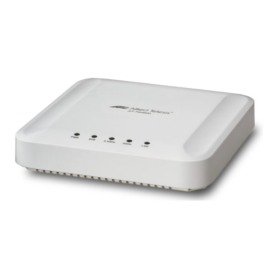
Page 23: Leds
AT-TQ4600 Wireless Access Point Installation Guide LEDs The LEDs on the AT-TQ4600 Access Point are described in Table 3. Table 3. LEDs on the AT-TQ4600 Access Point State Description Solid Green The unit is receiving DC power that is within the normal operating range. -
Page 24: Reset Button
Chapter 1: Overview Reset Button The Reset button on the rear panel is used to return the parameter settings of the unit to their default values. You might use the button if you want to discard the current configuration of the device or because you forgot the password to the manager account and cannot manage the unit. -
Page 25: Chapter 2: Installing The Access Point
Chapter 2 Installing the Access Point This chapter describes how to install the AT-TQ4600 Wireless Access Point. This chapter contains the following sections: “Reviewing Safety Precautions” on page 26 “Unpacking the AT-TQ4600 Access Point” on page 28 ... -
Page 26: Reviewing Safety Precautions
indicates that a translation of the safety statement is available in a PDF document titled Translated Safety Statements on the Allied Telesis website at www.alliedtelesis.com/support. Warning To prevent electric shock, do not remove the cover. No user- serviceable parts inside. This unit contains hazardous voltages and should only be opened by a trained and qualified technician. - Page 27 AT-TQ4600 Wireless Access Point Installation Guide Warning Operating Temperature. This product is designed for a maximum ambient temperature of 40°C Warning To reduce the risk of electric shock, the PoE port on this product must not connect to cabling that is routed outside the building where ...
-
Page 28: Unpacking The At-Tq4600 Access Point
One bracket and one base plate for wall or ceiling mounting If any item is missing or damaged, contact your Allied Telesis sales representative for assistance. If you are not using the PoE feature on the LAN port of the access point to power the device, you need to separately order the AT-TQ0091 AC/DC Power Adapter. -
Page 29: Installing The Access Point On A Wall Or Ceiling
AT-TQ4600 Wireless Access Point Installation Guide Installing the Access Point on a Wall or Ceiling This procedure contains the following sections. “Guidelines” “Mounting the Base Plate to the Wall or Ceiling” on page 30 “Attaching the Mounting Bracket to the Access Point” on page 31 ... -
Page 30: Mounting The Base Plate To The Wall Or Ceiling
Chapter 2: Installing the Access Point Mounting the To mount the base plate to the wall or ceiling, perform the following: Base Plate to the 1. Using the base plate as a template, mark the four holes for mounting Wall or Ceiling the base plate to the wall or ceiling. -
Page 31: Attaching The Mounting Bracket To The Access Point
AT-TQ4600 Wireless Access Point Installation Guide Attaching the To attach the mounting bracket to the access point, perform the following: Mounting 1. Place the access point upside down on a flat surface. Bracket to the 2. Place the bracket against the bottom of the access point and use the Access Point bracket to push downward on the stopper nub (see Figure 6). -
Page 32: Attaching The Access Point To The Base Plate
Chapter 2: Installing the Access Point Figure 8. Attaching the Mounting-Bracket Screw Attaching the To attach the access point and mounting bracket to the base plate on the wall or ceiling, perform the following: Access Point to the Base Plate 1. -
Page 33: Cabling The Access Point
AT-TQ4600 Wireless Access Point Installation Guide 4. Fasten the access point to the base plate by turning the base-plate captive screw clockwise using a Phillips-head screwdriver, as shown in Figure 9 on page 32. Cabling the To install cabling on the access point, perform the following: Access Point 1. -
Page 34: Figure 11: Connecting The Power Cable From The At-Tq0091 Ac/Dc Adapter
Chapter 2: Installing the Access Point Figure 11. Connecting the Power Cable from the AT-TQ0091 AC/DC Adapter 5. Check the AC plug on the AC/DC Power Adapter to see if it is the correct plug for your region. If it is not the correct plug, remove it by pushing down on the release tab and sliding it from the slot on the adapter. -
Page 35: Figure 13: Installing An Ac Plug On The At-Tq0091 Ac/Dc Power Adapter
AT-TQ4600 Wireless Access Point Installation Guide 6. Slide the correct AC plug for your region into the slot on the adapter until it clicks into place. Refer to Figure 13. Figure 13. Installing an AC Plug on the AT-TQ0091 AC/DC Power Adapter 7. -
Page 36: Kensington Lock
Chapter 2: Installing the Access Point Kensington Lock A Kensington lock can be used to secure the device. The lock is located on the rear panel (see Figure 14.) Kensington Lock Figure 14. Kensington Lock... -
Page 37: Starting The Initial Management Session On The Access Point
AT-TQ4600 Wireless Access Point Installation Guide Starting the Initial Management Session on the Access Point When you power on the access point for the first time, it queries the subnet on the LAN port for a DHCP server. If a DHCP server responds to its query, the unit uses the IP address the server assigns to it. -
Page 38: Starting The Initial Management Session With A Direct Connection
Chapter 2: Installing the Access Point Starting the To start the management session with a direct Ethernet connection between your computer and the access point, perform the following Initial procedure: Management Session with a Note Direct If the unit is using PoE for power, and you did not order an AC/DC Connection adapter with the unit, you cannot perform this procedure because it requires removing the network cable from the LAN port. -
Page 39: Starting The Initial Management Session Without A Dhcp Server
AT-TQ4600 Wireless Access Point Installation Guide Starting the This procedure explains how to start the initial management session on the access point when the LAN port is connected to an Ethernet switch on Initial a network that does not have a DHCP server. To start the management... - Page 40 Chapter 2: Installing the Access Point 5. Enter “manager” for the username and “friend” for the password. The username and password are case-sensitive.
-
Page 41: Setting The Country Setting
AT-TQ4600 Wireless Access Point Installation Guide Setting the Country Setting You should set the country setting during the initial management session of the access point to ensure that the device operates in compliance with the codes and regulations of your region or country. - Page 42 If the setting is not correct for your country or region, contact your Allied Telesis sales representative for assistance. The access point displays a confirmation prompt. 3. Click OK to change the country setting or Cancel to cancel the procedure.
-
Page 43: Appendix A: Technical Specifications
“LAN Port” on page 45 “Safety and Electromagnetic Emissions Certifications” on page 47 Physical Specifications Table 4. AT-TQ4600 Physical Specifications Dimensions (W x D x H) 170.0 mm x 170.0 mm x 35.0 mm (6.7 in. x 6.7 in. x 1.4 in.) Weight 0.47 kg (1 lb.) -
Page 44: Power Specifications
Appendix A: Technical Specifications Power Specifications Table 6. AT-TQ4600 Maximum Power Consumption AT-TQ4600 16 watts Table 7. AT-TQ0091 Power Adapter Input Range 240 Vac Input Frequency 47-63 Hz Input Power Consumption (no load) <0.3W max. Output Voltage +12 VDC Output Current... -
Page 45: Lan Port
AT-TQ4600 Wireless Access Point Installation Guide LAN Port Table 8. LAN Port Specifications Connector RJ45 Standards IEEE 802.3 (10Base-T) IEEE 802.3u (100Base-TX) IEEE 802.3ab (1000Base-T) PoE standard IEEE 802.3at (class 4) Figure 17 illustrates the pin layout of the LAN port. -
Page 46: Table 10. Mdi-X Pin Signals (10Base-T Or 100Base-Tx)
Appendix A: Technical Specifications Table 10 lists the pin signals for the MDI-X configuration at 10 or 100 Mbps. Table 10. MDI-X Pin Signals (10Base-T or 100Base-TX) Signal Table 11 lists the pin signals when the LAN port is operating at 1000 Mbps. -
Page 47: Safety And Electromagnetic Emissions Certifications
AT-TQ4600 Wireless Access Point Installation Guide Safety and Electromagnetic Emissions Certifications Table 12. Safety and Electromagnetic Emissions Certificates Standard RoHs compliant Compliance European Union RoHS (Directive 2011/65/EU of the European Parliament and of the Council of 8 June 2011 on the restriction of the use of certain hazardous substances in electrical and electronic equipment.) - Page 48 Appendix A: Technical Specifications Table 12. Safety and Electromagnetic Emissions Certificates (Continued) Safety EN 60950-1 IEC 60950-1 TUV-T UL 60950-1...
-
Page 49: Appendix B: Regulatory Statements
Appendix B Regulatory Statements This appendix contains the following regulatory statements: “Federal Communication Commission Interference Statement” on page 50 “Industry Canada Statement” on page 52 “Europe - EU Declaration of Conformity” on page 54... -
Page 50: Federal Communication Commission Interference Statement
Appendix B: Regulatory Statements Federal Communication Commission Interference Statement This device complies with Part 15 of the FCC Rules. Operation is subject to the following two conditions: (1) This device may not cause harmful interference, and (2) this device must accept any interference received, including interference that may cause undesired operation. - Page 51 AT-TQ4600 Wireless Access Point Installation Guide Country Code Selection (WiFi Devices) Note The non-US model of this product has a country code setting that must be set during the initial management session of the unit. The setting ensures that the unit operates in compliance with the laws and regulations of your country or region.
-
Page 52: Industry Canada Statement
Appendix B: Regulatory Statements Industry Canada Statement This device complies with RSS-210 of the Industry Canada Rules. Operation is subject to the following two conditions: (1) This device may not cause harmful interference, and (2) this device must accept any interference received, including interference that may cause undesired operation. - Page 53 AT-TQ4600 Wireless Access Point Installation Guide (ii) le gain maximal d’antenne permis pour les dispositifs utilisant les bandes 5 250-5 350 MHz et 5 470-5 725 MHz doit se conformer à la limite de p.i.r.e.; (iii) le gain maximal d’antenne permis (pour les dispositifs utilisant la bande 5 725-5 825 MHz) doit se conformer à...
-
Page 54: Europe - Eu Declaration Of Conformity
Appendix B: Regulatory Statements Europe - EU Declaration of Conformity This device complies with the essential requirements of the R&TTE Directive 1999/5/EC. The following test methods have been applied in order to prove presumption of conformity with the essential requirements of the R&TTE Directive 1999/5/EC: ... -
Page 55: Table 13. Declaration Of Conformity
Directive 1999/5/EC. Español Por medio de la presente Allied Telesis declara que el [Spanish] wireless access point cumple con los requisitos esenciales y cualesquiera otras disposiciones aplicables o exigibles de la Directiva 1999/5/CE. - Page 56 Allied Telesis declara que este wireless access point [Portuguese está conforme com os requisitos essenciais e outras disposições da Directiva 1999/5/CE. Slovensko Allied Telesis izjavlja, da je ta wireless access point v [Slovenian] skladu z bistvenimi zahtevami in ostalimi relevantnimi določili direktive 1999/5/ES. Slovensky Allied Telesis týmto vyhlasuje, že wireless access point...
- Page 57 AT-TQ4600 Wireless Access Point Installation Guide Table 13. Declaration of Conformity (Continued) Country Declaration Statement Svenska Härmed intygar Allied Telesis att denna wireless access [Swedish] point står I överensstämmelse med de väsentliga egenskapskrav och övriga relevanta bestämmelser som framgår av direktiv 1999/5/EG.
- Page 58 Appendix B: Regulatory Statements...
Need help?
Do you have a question about the AT-TQ4600 and is the answer not in the manual?
Questions and answers