Table of Contents
Advertisement
Quick Links
Download this manual
See also:
User Manual
Advertisement
Table of Contents

Subscribe to Our Youtube Channel
Related Manuals for Allied Telesis AT-TQ2450


Summary of Contents for Allied Telesis AT-TQ2450
-
Page 1: Installation Guide
Review Draft - March 18, 2012 AT-TQ2450 2.4 and 5 GHz Wireless Access Point Installation Guide 613-001820 Rev. A... - Page 2 Telesis, Inc. be liable for any incidental, special, indirect, or consequential damages whatsoever, including but not limited to lost profits, arising out of or related to this manual or the information contained herein, even if Allied Telesis, Inc. has been advised of, known, or should have known, the possibility of such damages.
-
Page 3: Electrical Safety And Emissions Standards
This product meets the following standards. Federal Communications Commission Interference Statement Declaration of Conformity Manufacturer Name: Allied Telesis, Inc. Declares that the product: wireless access point Model Number: AT-TQ2450 This device complies with Part 15 of the FCC Rules. Operation is subject to the following two conditions: (1) This device may not cause harmful interference, and (2) this device must accept any interference received, including interference that may cause undesired operation. - Page 4 European Union Restriction of the Use of Certain Hazardous Substances (RoHS) in Electrical and Electronic Equipment This Allied Telesis RoHS-compliant product conforms to the European Union Restriction of the Use of Certain Hazardous Substances (RoHS) in Electrical and Electronic Equipment. Allied Telesis ensures RoHS conformance by requiring supplier Declarations of Conformity, monitoring incoming materials, and maintaining manufacturing process controls.
-
Page 5: Translated Safety Statements
Translated Safety Statements Important: The indicates that a translation of the safety statement is available in a PDF document titled “Translated Safety Statements” on the Allied Telesis website at www.alliedtelesis.com/support/software. After you have accessed this website, enter the model number in the Search by Product Name box and then click Find to view the current list of documents. - Page 6 Review Draft - March 18, 2012...
-
Page 7: Table Of Contents
Reset Button..............................25 Chapter 2: Installing the Access Point ......................27 Reviewing Safety Precautions..........................28 Unpacking the AT-TQ2450 Access Point ......................30 Installing the Access Point on a Table......................32 Installing the Access Point on a Wall of Ceiling with the AT-BRKT-J26 Bracket..........36 Guidelines ..............................36 Attaching the Bottom Panel to the Wall or Ceiling ..................39... - Page 8 Review Draft - March 18, 2012 Contents...
- Page 9 Figure 3: 2.4 and 5 GHz Antenna Connectors ....................21 Figure 4: AT-TQ2450 Access Point Items ....................... 30 Figure 5: AT-TQ2450 Access Point Power Cords ................... 31 Figure 6: Installing the Rubber Feet ........................ 32 Figure 7: Installing the Antenna........................32 Figure 8: Attaching the Network Cable to the LAN Port ..................
- Page 10 Review Draft - March 18, 2012 List of Figures...
- Page 11 Table 1. Rear Panel Components ........................20 Table 2. Twisted Pair Cable for the LAN Port ....................23 Table 3. LEDs on the AT-TQ2450 Access Point .................... 24 Table 4. AT-TQ2450 Physical Specifications ....................53 Table 5. AT-BRKT-J26 Physical Specifications ....................53 Table 6.
- Page 12 Review Draft - March 18, 2012 List of Tables...
-
Page 13: Preface
Review Draft - March 18, 2012 Preface This guide contains the hardware installation instructions for the AT- TQ2450 wireless access point. This preface contains the following sections: “Safety Symbols Used in this Document” on page 14 “Contacting Allied Telesis” on page 15 ... -
Page 14: Safety Symbols Used In This Document
Review Draft - March 18, 2012 Preface Safety Symbols Used in this Document This document uses the following conventions. Note Notes provide additional information. Caution Cautions inform you that performing or omitting a specific action may result in equipment damage or loss of data. Warning Warnings inform you that performing or omitting a specific action may result in bodily injury. -
Page 15: Contacting Allied Telesis
AT-TQ2450 Installation Guide Contacting Allied Telesis If you need assistance with this product, you may contact Allied Telesis technical support by going to the Support & Services section of the Allied Telesis web site at www.alliedtelesis.com/support. You can find links for the following services on this page: 24/7 Online Support —... - Page 16 Review Draft - March 18, 2012 Preface...
-
Page 17: Chapter 1: Overview
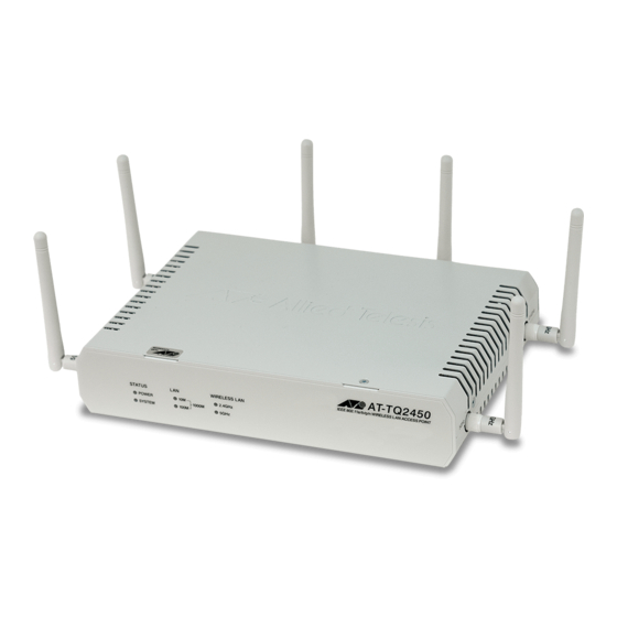
Review Draft - March 18, 2012 Chapter 1 Overview This chapter describes the hardware components of the AT-TQ2450 Chassis. This chapter contains the following sections: “Features” on page 18 “Front and Rear Panels” on page 19 “2.44 and 5 GHz Antenna Connectors” on page 21 ... -
Page 18: Features
Review Draft - March 18, 2012 Chapter 1: Overview Features The main features of the product are listed here: Independent 2.4 and 5 GHz radios IEEE 802.11a/b/g IEEE 802.11n 2x2 MIMO chains with antenna diversity Up to 600 Mbps throughput ... -
Page 19: Front And Rear Panels
Review Draft - March 18, 2012 AT-TQ2450 Installation Guide Front and Rear Panels The front and rear panels of the unit are illustrated in Figure 1 and Figure 2. Power and LAN Port Radio System Status LEDs LEDs LEDs Figure 1. Front Panel The LEDs are described in “LEDs”... -
Page 20: Table 1. Rear Panel Components
Review Draft - March 18, 2012 Chapter 1: Overview Table 1. Rear Panel Components Field Description Console Port The Console Port is for manufacturing purposes only. Rest Button The Reset button returns the parameter settings on the access point to their default settings. -
Page 21: And 5 Ghz Antenna Connectors
Review Draft - March 18, 2012 AT-TQ2450 Installation Guide 2.44 and 5 GHz Antenna Connectors The access point has two independent radios that operate ar 2.4 and 5 GHz. Each radio has three connectors on the side and rear panels of the device. -
Page 22: Lan Port
The LAN port is used to connect your wireless network to your wired network, typically through an Ethernet switch. Power over The AT-TQ2450 Access Point supports Power over Ethernet on the LAN port. The unit is a PoE class 3 device with a maximum power consumption Ethernet of 11 watts. -
Page 23: Automatic Mdix Detection
Review Draft - March 18, 2012 AT-TQ2450 Installation Guide Table 2. Twisted Pair Cable for the LAN Port 10Mbps 100Mbps 1000Mbps Cable Type Non- Non- Non- Standard TIA/EIA 568- B-compliant Category 3 shielded or unshielded cabling with 100 ohm impedance and a frequency of 16 MHz. -
Page 24: Leds
Review Draft - March 18, 2012 Chapter 1: Overview LEDs The LEDs on the AT-TQ2450 Access Port are described in Table 3. Table 3. LEDs on the AT-TQ2450 Access Point State Description Power Solid Green The unit is receiving DC power that is within the normal operating range. -
Page 25: Reset Button
Review Draft - March 18, 2012 AT-TQ2450 Installation Guide Reset Button The Reset button on the rear panel is used to return the parameter settings of the unit to their default values. You might use the button if you want to discard the current configuration of the device or cannot manage the unit because you forgot the password to the manager account. - Page 26 Review Draft - March 18, 2012 Chapter 1: Overview...
-
Page 27: Chapter 2: Installing The Access Point
Review Draft - March 18, 2012 Chapter 2 Installing the Access Point This chapter describes how to install the AT-TQ2450 Access Point. This chapter contains the following sections: “Reviewing Safety Precautions” on page 28 “Unpacking the AT-TQ2450 Access Point” on page 30 ... -
Page 28: Reviewing Safety Precautions
Review Draft - March 18, 2012 Chapter 2: Installing the Access Point Reviewing Safety Precautions Please review the following safety precautions before you begin to install the access point. Note The indicates that a translation of the safety statement is available for viewing in the “Translated Safety Statements”... - Page 29 Review Draft - March 18, 2012 AT-TQ2450 Installation Guide Warning Operating Temperature. This product is designed for a maximum ambient temperature of 40° degrees C. E7 Note All Countries: Install product in accordance with local and National Electrical Codes. E8...
-
Page 30: Unpacking The At-Tq2450 Access Point
As you unpack the access point, check the shipping container for the components listed in Figure 4. If any item is missing or damaged, contact your Allied Telesis sales representative for assistance. One AT-TQ2450 Access Point Three 2.4 GHz antennas... -
Page 31: Figure 5: At-Tq2450 Access Point Power Cords
(North America, Europe, Australia, and United Kingdom) 1692 1691 Figure 5. AT-TQ2450 Access Point Power Cords 1. Do one of the following: To install the unit on a table, go to “Installing the Access Point on a Table” on page 32. -
Page 32: Installing The Access Point On A Table
Review Draft - March 18, 2012 Chapter 2: Installing the Access Point Installing the Access Point on a Table To install the access point on a table, perform the following procedure: 1. Place the access point upside down on a table. 2. -
Page 33: Figure 8: Attaching The Network Cable To The Lan Port
Review Draft - March 18, 2012 AT-TQ2450 Installation Guide N S O 5 G H R E S R E S L A N 1 0 B A S E (A U -T /1 0 0 B P o E... -
Page 34: Figure 10: Attaching The Dc Power Cable
Review Draft - March 18, 2012 Chapter 2: Installing the Access Point 6. Connect the DC cable on the AC/DC adapter to the 12VDC connector on the access point. Refer to Figure 10. N S O 5 G H R E S R E S L A N 1 0 B... -
Page 35: Figure 11: Securing The Dc Power Cord To The Access Point With The Tie Wrap
Review Draft - March 18, 2012 AT-TQ2450 Installation Guide N S O 5 G H R E S R E S L A N 1 0 B A S E (A U -T /1 0 0 B P o E... -
Page 36: Installing The Access Point On A Wall Of Ceiling With The At-Brkt-J26 Bracket
Review Draft - March 18, 2012 Chapter 2: Installing the Access Point Installing the Access Point on a Wall of Ceiling with the AT-BRKT-J26 Bracket This section contains the procedure for installing the access point on a wall or ceiling with the optional AT-BRKT-J26 bracket. The bracket consists of top and bottom panels. -
Page 37: Figure 13: Flange On The Bottom Panel Of The At-Brkt-J26 Bracket
Review Draft - March 18, 2012 AT-TQ2450 Installation Guide Flange Figure 13. Flange on the Bottom Panel of the AT-BRKT-J26 Bracket You should verify that the wall or ceiling material is strong enough to support the weight of the bracket and access point. -
Page 38: Figure 14: Screw Holes On The Bottom Panel Of The At-Brkt-J26 Bracket
Review Draft - March 18, 2012 Chapter 2: Installing the Access Point Screw Holes Screw Holes Figure 14. Screw Holes on the Bottom Panel of the AT-BRKT-J26 Bracket The holes have a diameter of 4.5 mm (0.2 in.). Refer to Figure 15. ... -
Page 39: Attaching The Bottom Panel To The Wall Or Ceiling
Review Draft - March 18, 2012 AT-TQ2450 Installation Guide To attach the bottom panel of the bracket to the wall or ceiling, preform the Attaching the following procedure: Bottom Panel to the Wall or Note Ceiling Please review “Guidelines” on page 36 before performing this procedure. -
Page 40: Attaching The Access Point To The Top Panel
1. Place the AT-TQ2450 Access Point upside down on a table or desk, with the rear panel facing you. Refer to Figure 18 on page 41. -
Page 41: Figure 18: Rear Panel Upside Down
Review Draft - March 18, 2012 AT-TQ2450 Installation Guide Figure 18. Rear Panel Upside Down 2. Locate the two screw holes on the rear panel. The holes are used to secure the top panel to the access point. Refer to Figure 19. -
Page 42: Figure 20: Attaching The Top Panel To The Access Point
Review Draft - March 18, 2012 Chapter 2: Installing the Access Point Figure 20. Attaching the Top Panel to the Access Point 4. Place the top panel and access point over the bottom panel on the wall or ceiling such that the two anchor pins on the bottom panel fit into the holes on the top panel. -
Page 43: Figure 21: Attaching The Top Panel And Access Point To The Bottom Panel
Review Draft - March 18, 2012 AT-TQ2450 Installation Guide Anchor Pins Figure 21. Attaching the Top Panel and Access Point to the Bottom Panel... -
Page 44: Figure 22: Tightening The Screws To Secure The Top Panel And Access Port To The Bottom Panel
Review Draft - March 18, 2012 Chapter 2: Installing the Access Point 5. Secure the top panel and access point to the bottom panel by tightening the two captive screws on the top panel. Refer to Figure 22. Screws Figure 22. Tightening the Screws to Secure the Top Panel and Access Port to the Bottom Panel 6. -
Page 45: Figure 23: Installing The Antennas
Review Draft - March 18, 2012 AT-TQ2450 Installation Guide Figure 23. Installing the Antennas 7. Attach a network cable to the LAN port. Refer to Figure 24. Figure 24. Attaching the LAN Cable... -
Page 46: Figure 25: Connecting The Power Cord To The Ac/Dc Adapter
Review Draft - March 18, 2012 Chapter 2: Installing the Access Point 8. Connect the other end of the network cable to a port on an Ethernet switch. 9. If you are not using the PoE feature on the Ethernet port to power the unit, continue with this procedure to attach the AC/DC power adapter. -
Page 47: Figure 26: Attaching The Dc Power Cable
Review Draft - March 18, 2012 AT-TQ2450 Installation Guide Figure 26. Attaching the DC Power Cable 12. Secure the DC cable to one of the anchors on the bottom panel with the tie wrap that comes with the access point. Refer to Figure 27 on... -
Page 48: Figure 27: Securing The Dc Power Cord To The At-Brkt-J26 Bracket With The Tie Wrap
Review Draft - March 18, 2012 Chapter 2: Installing the Access Point Anchors Figure 27. Securing the DC Power Cord to the AT-BRKT-J26 Bracket with the Tie Wrap 13. Connect the AC plug on the power cord to an appropriate AC power source. -
Page 49: Installing Anti-Theft Devices
When an anti-theft device is installed on the bracket, the top panel and access point cannot be removed from the bottom panel. The holes are identified in Figure 28. Note Anti-theft devices are not available from Allied Telesis. Kensington Lock Padlock Torx or similar screw (M3 x 4mm) Figure 28. -
Page 50: Starting The Initial Management Session On The Access Point
Review Draft - March 18, 2012 Chapter 2: Installing the Access Point Starting the Initial Management Session on the Access Point When you power on the access point for the first time, it queries the subnet on the LAN port for a DHCP server. If a DHCP server responds to its query, the unit uses the IP address the server assigns to it. -
Page 51: Starting The Initial Management Session With A Direct Connection
Review Draft - March 18, 2012 AT-TQ2450 Installation Guide To start the management session with a direct Ethernet connection Starting the between your computer and the access port, perform the following Initial procedure: Management Session with a Note Direct If the access point is using PoE, you may not perform this procedure... -
Page 52: Starting The Initial Management Session With A Dhcp Server
Review Draft - March 18, 2012 Chapter 2: Installing the Access Point 2. Change the IP address on your computer to 192.168.1.n, where n is a number from 1 to 254, but not 230. Refer to the documentation that accompanies your computer for instructions on how to set the IP address. -
Page 53: Appendix A: Technical Specifications
Review Draft - March 18, 2012 Appendix A Technical Specifications Physical Specifications Table 4. AT-TQ2450 Physical Specifications Dimensions (W x D x H) 228 mm x 160 mm x 44 mm (8.98 in. x 6.3 in. x 1.74 in.) Weight (kilograms) 1 kg (2.2 lbs) -
Page 54: Power Specifications
Review Draft - March 18, 2012 Appendix A: Technical Specifications Power Specifications Table 7. AT-TQ2450 Maximum Power Consumption AT-TQ2450 11.0 W Table 8. Power Adapter Input Input Range 100-240 AC @ 47-63 Hz Input Connector IEC320-C14 (3-Pole AC inlet) Table 9. Power Adapter Output... -
Page 55: Lan Port
Review Draft - March 18, 2012 AT-TQ2450 Installation Guide LAN Port Table 10. LAN Port Specifications Connector RJ-45 Standards IEEE 802.3 (10Base-T) IEEE 802.3u (100Base-TX) IEEE 802.3ab (1000Base-T) PoE standard IEEE 802.3af (class 3) Figure 29 illustrates the pin layout of the LAN port. -
Page 56: Table 13. 1000Base-T Connector Pinouts
Review Draft - March 18, 2012 Appendix A: Technical Specifications Table 12. MDI-X Pin Signals (10Base-T or 100Base-TX) (Continued) Signal Table 13 lists the pin signals when the LAN port is operating at 1000 Mbps. Table 13. 1000Base-T Connector Pinouts Pair Signal TX and RX+... -
Page 57: Safety And Electromagnetic Emissions Certifications
Review Draft - March 18, 2012 AT-TQ2450 Installation Guide Safety and Electromagnetic Emissions Certifications Safety and Electromagnetic Emissions: Table 14. Certificates Standard Compliance RoHs compliant Electromagnetic Compatibility ETSI EN 61000-6-3:2007 (EMC) ETSI EN 301 489-17 v2.11 FCC 47 CFR Part 15, Subpart B... - Page 58 Review Draft - March 18, 2012 Appendix A: Technical Specifications...
-
Page 59: Appendix B: Regulatory Statements
Review Draft - March 18, 2012 Appendix B Regulatory Statements This appendix contains the following regulatory statements: “Federal Communication Commission Interference Statement” on page 60 “Industry Canada Statement” on page 61 “Europe - EU Declaration of Conformity” on page 63 ... -
Page 60: Federal Communication Commission Interference Statement
Review Draft - March 18, 2012 Appendix B: Regulatory Statements Federal Communication Commission Interference Statement This device complies with Part 15 of the FCC Rules. Operation is subject to the following two conditions: (1) This device may not cause harmful interference, and (2) this device must accept any interference received, including interference that may cause undesired operation. -
Page 61: Industry Canada Statement
Review Draft - March 18, 2012 AT-TQ2450 Installation Guide Industry Canada Statement This device complies with RSS-210 of the Industry Canada Rules. Operation is subject to the following two conditions: (1) This device may not cause harmful interference, and (2) this device must accept any interference received, including interference that may cause undesired operation. - Page 62 Review Draft - March 18, 2012 Appendix B: Regulatory Statements pour l’exploitation point à point et non point à point, selon le cas. (iv) De plus, les utilisateurs devraient aussi être avisés que les utilisateurs de radars de haute puissance sont désignés utilisateurs principaux (c.-à- d., qu’ils ont la priorité) pour les bandes 5 250-5 350 MHz et 5 650-5 850 MHz et que ces radars pourraient causer du brouillage et/ou des dommages aux dispositifs LAN-EL.
-
Page 63: Europe - Eu Declaration Of Conformity
Review Draft - March 18, 2012 AT-TQ2450 Installation Guide Europe - EU Declaration of Conformity This device complies with the essential requirements of the R&TTE Directive 1999/5/EC. The following test methods have been applied in order to prove presumption of conformity with the essential requirements of the R&TTE Directive 1999/5/EC:... - Page 64 Directive 1999/5/EC. Español Por medio de la presente Allied Telesis declara que el [Spanish] wireless access point cumple con los requisitos esenciales y cualesquiera otras disposiciones aplicables o exigibles de la Directiva 1999/5/CE.
- Page 65 Allied Telesis declara que este wireless access point [Portuguese está conforme com os requisitos essenciais e outras disposições da Directiva 1999/5/CE. Slovensko Allied Telesis izjavlja, da je ta wireless access point v [Slovenian] skladu z bistvenimi zahtevami in ostalimi relevantnimi določili direktive 1999/5/ES. Slovensky Allied Telesis týmto vyhlasuje, že wireless access point...
- Page 66 Review Draft - March 18, 2012 Appendix B: Regulatory Statements Svenska Härmed intygar Allied Telesis att denna wireless access [Swedish] point står I överensstämmelse med de väsentliga egenskapskrav och övriga relevanta bestämmelser som framgår av direktiv 1999/5/EG.
Need help?
Do you have a question about the AT-TQ2450 and is the answer not in the manual?
Questions and answers