
Subscribe to Our Youtube Channel
Related Manuals for Allied Telesis AT-TQ4400e


Summary of Contents for Allied Telesis AT-TQ4400e
-
Page 1: Installation Guide
AT-TQ4400e Outdoor Wireless Access Point with IEEE802.11a/b/g/n/ac Dual Radio Installation Guide 613-002195 Rev. A... - Page 2 Allied Telesis, Inc. has been advised of, known, or should have known, the...
-
Page 3: Declaration Of Conformity
This product meets the following standards: Federal Communications Commission Interference Statement Declaration of Conformity Manufacturer Name: Allied Telesis, Inc. Declares that the product: Wireless access point with PoE+ powered device function Model Number: AT-TQ4400e This device complies with Part 15 of the FCC Rules. Operation is subject to the following two conditions: (1) This device may not cause harmful interference, and (2) this device must accept any interference received, including interference that may cause undesired operation. - Page 4 European Union Restriction of the Use of Certain Hazardous Substances (RoHS) in Electrical and Electronic Equipment This Allied Telesis RoHS-compliant product conforms to the European Union Restriction of the Use of Certain Hazardous Substances (RoHS) in Electrical and Electronic Equipment. Allied Telesis ensures RoHS conformance by requiring supplier Declarations of Conformity, monitoring incoming materials, and maintaining manufacturing process controls.
- Page 5 Electromagnetic Compatibility (EMC) EN 301 489-1 EN 301 489-17 EN 55022 EN 55024 EN 61000-3-2 EN 61000-3-3 EN 61000-4-2 EN 61000-4-3 EN 61000-4-4 EN 61000-4-5 EN 61000-4-6 EN 61000-4-8 ...
-
Page 6: Translated Safety Statements
CAN/CSA-C22.2 No. 60950-22-07 IEC 60950-22 IEC 60529 Translated Safety Statements Important: The indicates that a translation of the safety statement is available in a PDF document titled Translated Safety Statements on the Allied Telesis website at www.alliedtelesis.com/support. -
Page 7: Table Of Contents
Maximum Distance ..........................20 Chapter 2: Installing the Access Point ......................21 Reviewing Safety Precautions ........................22 Unpacking the AT-TQ4400e Access Point....................24 Attaching the Ground Cable to the Access Point ..................26 Guidelines............................26 What to Prepare for Attaching the Ground Cable ................26 Attaching the Ground Cable to the Access Point ................ - Page 8 Contents Appendix B: Regulatory Statements ......................49 Federal Communication Commission Interference Statement ..............50 Industry Canada Statement........................52 Europe - EU Declaration of Conformity ...................... 55 Europe – EU Declaration of Conformity ....................55...
-
Page 9: Preface
Preface This guide contains the hardware installation instructions for the AT-TQ4400e Outdoor Wireless Access Point. This preface contains the following sections: “Safety Symbols Used in this Document” on page 10 “Contacting Allied Telesis” on page 11 ... -
Page 10: Safety Symbols Used In This Document
Preface Safety Symbols Used in this Document This document uses the following conventions. Note Notes provide additional information. Caution Cautions inform you that performing or omitting a specific action may result in equipment damage or loss of data. Warning Warnings inform you that performing or omitting a specific action may result in bodily injury. -
Page 11: Contacting Allied Telesis
AT-TQ4400e Outdoor Wireless Access Point Installation Guide Contacting Allied Telesis If you need assistance with this product, you may contact Allied Telesis technical support by going to the Support & Services section of the Allied Telesis web site at www.alliedtelesis.com/support. You can find links for the following services on this page: 24/7 Online Support —... - Page 12 Preface...
-
Page 13: Chapter 1: Product Description
Chapter 1 Product Description This chapter describes the hardware components of the AT-TQ4400e Wireless Access Point. This chapter contains the following sections: “Overview” on page 14 “Features” on page 16 “LAN Port” on page 18 “Cable Specifications” on page 20... -
Page 14: Overview
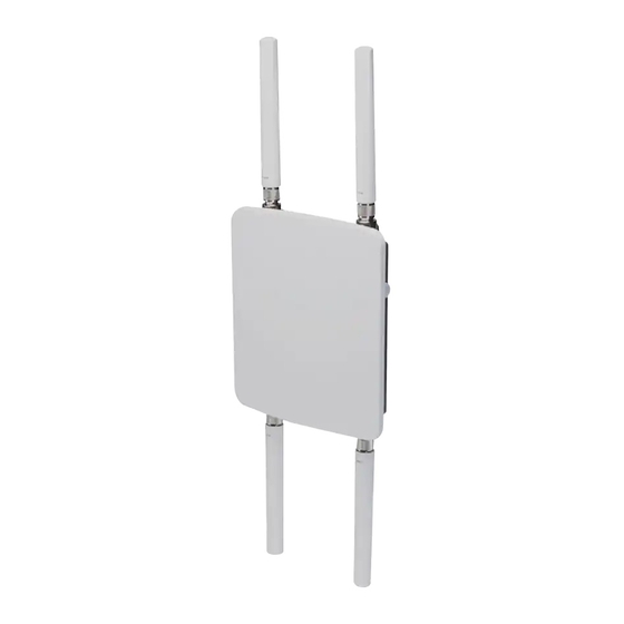
The bottom panel components of the AT-TQ4400e Access Point are illustrated in Figure 2. LAN Port 2.4GHz Antenna Connector 5GHz Antenna Connector Figure 2. AT-TQ4400e Access Point Antenna Panel Bottom Figure 3 on page 15 shows the side view of the AT-TQ4400e Access Point. - Page 15 AT-TQ4400e Outdoor Wireless Access Point Installation Guide Gore® vent Figure 3. AT-TQ4400e Access Point Side Panel The components are listed in Table 1. Table 1. Components of the Access Point Component Description 5 GHz Antenna N-type female connector for the 5 GHz...
-
Page 16: Features
Chapter 1: Product Description Features The main features of the product are listed here: Dual radio: 2.4 GHz and 5 GHz IEEE 802.11a/b/g/n/ac 2x2:2ss MIMO Maximum capacity 2.4 GHz: 300 Mbps Maximum capacity 5 GHz: 867 Mbps ... - Page 17 AT-TQ4400e Outdoor Wireless Access Point Installation Guide Metallic chassis with plastic cover to repel ultraviolet (UV) radiation from the sun...
-
Page 18: Lan Port
Chapter 1: Product Description LAN Port The AT-TQ4400e wireless access point has one LAN port to connect to your Local Area Network (LAN), typically through an Ethernet switch. Power over The AT-TQ4400e Access Point supports Power over Ethernet Plus (PoE+) on the LAN port. The access point is a PoE+ class 4 powered Ethernet (PoE) device with a maximum power consumption of 16 watts. -
Page 19: Port Pinouts
AT-TQ4400e Outdoor Wireless Access Point Installation Guide You may not disable automatic MDIX detection. For automatic MDIX detection to work properly, it must also be present on the Ethernet switch. The LAN port defaults to MDIX if it is connected to a network device that does not support automatic MDIX detection. -
Page 20: Cable Specifications
Chapter 1: Product Description Cable Specifications To connect the AT-TQ4400e wireless access point to your LAN, you must provide cables. Here are cable requirements and options. Cable The cable requirements for the LAN port are listed in Table 2. Requirements Table 2. -
Page 21: Chapter 2: Installing The Access Point
Chapter 2 Installing the Access Point This chapter describes how to install the AT-TQ4400e Wireless Access Point. This chapter contains the following sections: “Reviewing Safety Precautions” on page 22 “Unpacking the AT-TQ4400e Access Point” on page 24 “Attaching the Ground Cable to the Access Point” on page 26 ... -
Page 22: Reviewing Safety Precautions
available in a PDF document titled Translated Safety Statements on the Allied Telesis website at www.alliedtelesis.com/support. Warning To prevent electric shock, do not remove the cover. No user- serviceable parts inside. This unit contains hazardous voltages and should only be opened by a trained and qualified technician. - Page 23 AT-TQ4400e Outdoor Wireless Access Point Installation Guide Note You should verify that your PoE network adheres to the standards of a separated extra-low voltage (SELV) circuit before using the PoE feature on the wireless access point. Warning Only trained and qualified personnel are allowed to install or to replace this equipment.
-
Page 24: Unpacking The At-Tq4400E Access Point
Chapter 2: Installing the Access Point Unpacking the AT-TQ4400e Access Point To unpack the AT-TQ4400e access point, perform the following procedure: 1. Remove all components from the shipping boxes. Note Store the packaging material in a safe location. You must use the original shipping material if you need to return the unit to Allied Telesis. - Page 25 2 x Antenna connector 4 x Screw for the mounting base 4 x Screw for the pole- mount bracket 1 x Screw for the ground cable 3. If any item is missing or damaged, contact your Allied Telesis sales representative for assistance.
-
Page 26: Attaching The Ground Cable To The Access Point
What to Prepare You need the following items to attach the ground cable to the access point: for Attaching the Ground Cable AT-TQ4400e Access Point Ground cable One screw for the ground cable ... - Page 27 AT-TQ4400e Outdoor Wireless Access Point Installation Guide Figure 4. Aligning the Access Point with Ground Cable 2. Drive the screw through the holes to attach the ground cable to the access point. 3. Cut off the extra length of the ground cable to make it connected straight to the ground point.
-
Page 28: Connecting The Access Point With The Ethernet Cable
Chapter 2: Installing the Access Point Connecting the Access Point with the Ethernet Cable To connect the access point with the Ethernet cable, perform the following procedure: 1. Unscrew the sealing nut at the LAN port on the access point and remove the clamping claw and sealing insert. - Page 29 AT-TQ4400e Outdoor Wireless Access Point Installation Guide Figure 7. Applying the Sealing Parts to the LAN Cable 4. Connect the RJ-45 plug into the LAN port and screw the sealing nut to the access point as shown in Figure 8.
-
Page 30: Installing The Access Point On A Wall
Chapter 2: Installing the Access Point Installing the Access Point on a Wall The AT-TQ4400e access point can be mounted on a concrete or regular wall. To install the access point, perform one of the following procedures: “Installing the Access Point on a Concrete Wall” on page 30 ... - Page 31 AT-TQ4400e Outdoor Wireless Access Point Installation Guide 2. Using the mounting base as a template, mark four holes with a pencil. See Figure 9 on page 31 for hole dimensions. Figure 9. Base Plate Hole Dimensions 3. Pre-drill the marked locations on the concrete wall.
-
Page 32: Installing The Access Point On A Regular Wall
Chapter 2: Installing the Access Point 5. Install the four sets of bolts and wall anchors into the holes you made in Step 3. 6. Attach the nuts and washers to the bolts in the concrete wall to install the access point. See Figure 11. Figure 11. - Page 33 AT-TQ4400e Outdoor Wireless Access Point Installation Guide 4. Drive the tapping screws into the holes made in Step 2 to install the access point. See Figure 12 on page 33. Figure 12. Installing to the Wall Using Tapping Screws 5. Proceed to “Attaching the Antennas to the Access Point” on page 37.
-
Page 34: Installing The Access Point On A Pole
Chapter 2: Installing the Access Point Installing the Access Point on a Pole The AT-TQ4400e access point can be mounted on a vertical pole or horizontal pole as shown in Figure 13. Figure 13. Pole Installation of the Access Point... - Page 35 AT-TQ4400e Outdoor Wireless Access Point Installation Guide Note Attach the ground cable to the access point before attaching the mounting base to the access point. See “Attaching the Ground Cable to the Access Point” on page 26. 3. Orient the pole-mount bracket for installing to either a vertical pole or a horizontal pole.
- Page 36 Chapter 2: Installing the Access Point 7. Proceed to “Attaching the Antennas to the Access Point” on page 37.
-
Page 37: Attaching The Antennas To The Access Point
AT-TQ4400e Outdoor Wireless Access Point Installation Guide Attaching the Antennas to the Access Point To attach the antennas to the access point, perform the following procedure: 1. Screw a 5GHz antenna into the 5GHz antenna connector on the top panel of the access point. See Figure 16. -
Page 38: Starting The Initial Management Session On The Access Point
Chapter 2: Installing the Access Point Starting the Initial Management Session on the Access Point When you connect the access point to the PoE switch for the first time, it queries the subnet on the LAN port for a DHCP server. If a DHCP server responds to its query, the access point uses the IP address the server assigns to it. -
Page 39: Starting The Initial Management Session With A Dhcp Server
AT-TQ4400e Outdoor Wireless Access Point Installation Guide 2. Change the IP address on your management PC to 192.168.1.n. The n is any number from 1 to 254, except 230. Refer to the documentation that accompanies your PC for instructions on how to set the IP address. - Page 40 Chapter 2: Installing the Access Point The logon window appears as shown in Figure 17 on page 39. 4. Enter “manager” for the username and “friend” for the password. The username and password are case-sensitive.
-
Page 41: Setting The Country Setting
AT-TQ4400e Outdoor Wireless Access Point Installation Guide Setting the Country Setting You should set the country setting during the initial management session of the access point to ensure that the device operates in compliance with the codes and regulations of your region or country. - Page 42 If the setting is not correct for your country or region, contact your Allied Telesis sales representative for assistance. The access point displays a confirmation prompt. 3. Click OK to change the country setting or Cancel to cancel the procedure.
-
Page 43: Appendix A: Technical Specifications
“Safety and Electromagnetic Emissions Certifications” on page 47 Physical Specifications Table 4. AT-TQ4400e Physical Specifications Dimensions (W x D x H) 218 mm x 250 mm x 55.5 mm (8.6 in. x 9.8 in. x 2.2 in.) Weight 2 kg (4.4 lb.) -
Page 44: Power Specifications
Appendix A: Technical Specifications Power Specifications Table 6. AT-TQ4400e Maximum Power Consumption AT-TQ4400e 19.4 watts... -
Page 45: Lan Port
AT-TQ4400e Outdoor Wireless Access Point Installation Guide LAN Port Table 7. LAN Port Specifications Connector RJ45 Standards IEEE 802.3 (10Base-T) IEEE 802.3u (100Base-TX) IEEE 802.3ab (1000Base-T) PoE standard IEEE 802.3at (class 4) Figure 19 illustrates the pin layout of the LAN port. - Page 46 Appendix A: Technical Specifications Table 9 lists the pin signals for the MDI-X configuration at 10 or 100 Mbps. Table 9. MDI-X Pin Signals (10Base-T or 100Base-TX) Signal Table 10 lists the pin signals when the LAN port is operating at 1000 Mbps.
-
Page 47: Safety And Electromagnetic Emissions Certifications
AT-TQ4400e Outdoor Wireless Access Point Installation Guide Safety and Electromagnetic Emissions Certifications Table 11. Safety and Electromagnetic Emissions Certificates Standard RoHs compliant Compliance European Union RoHS (Directive 2011/65/EU of the European Parliament and of the Council of 8 June 2011 on the restriction of the use of certain hazardous substances in electrical and electronic equipment.) - Page 48 Appendix A: Technical Specifications Table 11. Safety and Electromagnetic Emissions Certificates (Continued) Safety EN 60950-1 IEC 60950-1 TUV-T UL 60950-1 UL 60950-22 CAN/CSA C22.2 No. 60950-1-07 CAN/CSA-C22.2 No. 60950-22-07 IEC 60950-22 IEC 60529...
-
Page 49: Appendix B: Regulatory Statements
Appendix B Regulatory Statements This appendix contains the following regulatory statements: “Federal Communication Commission Interference Statement” on page 50 “Industry Canada Statement” on page 52 “Europe - EU Declaration of Conformity” on page 55 ... -
Page 50: Federal Communication Commission Interference Statement
Appendix B: Regulatory Statements Federal Communication Commission Interference Statement This device complies with Part 15 of the FCC Rules. Operation is subject to the following two conditions: (1) This device may not cause harmful interference, and (2) this device must accept any interference received, including interference that may cause undesired operation. - Page 51 AT-TQ4400e Wireless Access Point Installation Guide Radiation Exposure Statement This equipment complies with FCC radiation exposure limits set forth for an uncontrolled environment. This equipment should be installed and operated with minimum distance 32cm between the radiator & your body.
-
Page 52: Industry Canada Statement
Appendix B: Regulatory Statements Industry Canada Statement This device complies with RSS-247 of the Industry Canada Rules. Operation is subject to the following two conditions: (1) This device may not cause harmful interference, and (2) this device must accept any interference received, including interference that may cause undesired operation. - Page 53 AT-TQ4400e Wireless Access Point Installation Guide (ii) le gain maximal d’antenne permis pour les dispositifs utilisant les bandes 5 250-5 350 MHz et 5 470-5 725 MHz doit se conformer à la limite de p.i.r.e.; (iii) le gain maximal d’antenne permis (pour les dispositifs utilisant la bande 5 725-5 825 MHz) doit se conformer à...
- Page 54 Appendix B: Regulatory Statements 5. Warning Please carefully select the installation position and make sure that the final output power does not exceed the limit set force in relevant rules. The violation of the rule could lead to serious federal penalty. Instructions d'installation professionnelle: 1.
-
Page 55: Europe - Eu Declaration Of Conformity
AT-TQ4400e Wireless Access Point Installation Guide Europe - EU Declaration of Conformity This device complies with the essential requirements of the R&TTE Directive 1999/5/EC. The following test methods have been applied in order to prove presumption of conformity with the essential requirements of the R&TTE Directive 1999/5/EC:... - Page 56 Directive 1999/5/EC. Español Por medio de la presente Allied Telesis declara que el [Spanish] wireless access point cumple con los requisitos esenciales y cualesquiera otras disposiciones aplicables o exigibles de la Directiva 1999/5/CE.
- Page 57 Allied Telesis declara que este wireless access point [Portuguese está conforme com os requisitos essenciais e outras disposições da Directiva 1999/5/CE. Slovensko Allied Telesis izjavlja, da je ta wireless access point v [Slovenian] skladu z bistvenimi zahtevami in ostalimi relevantnimi določili direktive 1999/5/ES. Slovensky Allied Telesis týmto vyhlasuje, že wireless access point...
- Page 58 Appendix B: Regulatory Statements Table 12. (Continued)Declaration of Conformity Country Declaration Statement Svenska Härmed intygar Allied Telesis att denna wireless access [Swedish] point står I överensstämmelse med de väsentliga egenskapskrav och övriga relevanta bestämmelser som framgår av direktiv 1999/5/EG.
Need help?
Do you have a question about the AT-TQ4400e and is the answer not in the manual?
Questions and answers