Allied Telesis AT-TQ5403 Series Installation Manual
Hide thumbs
Also See for AT-TQ5403 Series:
- Management software user manual (142 pages) ,
- User manual (98 pages) ,
- Installation manual (54 pages)
Table of Contents
Advertisement
Quick Links
Download this manual
See also:
User Manual
Advertisement
Table of Contents

Subscribe to Our Youtube Channel
Related Manuals for Allied Telesis AT-TQ5403 Series


Summary of Contents for Allied Telesis AT-TQ5403 Series
- Page 1 AT-TQ5403 Series Wireless Access Point AT-TQ5403 AT+TQm5403 Installation Guide 613-002713 Rev. A...
- Page 2 Allied Telesis, Inc. has been advised of, known, or should have known, the...
- Page 3 AT-TQ5403 Series Wireless Access Point Installation Guide Electrical Safety and Emissions Standards This product meets the following standards: “Federal Communications Commission Interference Statement” “European Union Restriction of the Use of Certain Hazardous Substances (RoHS) in Electrical and Electronic Equipment” on page 4 “Safety and Electromagnetic Emissions”...
- Page 4 European Union Restriction of the Use of Certain Hazardous Substances (RoHS) in Electrical and Electronic Equipment This Allied Telesis RoHS-compliant product conforms to the European Union Restriction of the Use of Certain Hazardous Substances (RoHS) in Electrical and Electronic Equipment. Allied Telesis ensures RoHS conformance by requiring supplier Declarations of Conformity, monitoring incoming materials, and maintaining manufacturing process controls.
- Page 5 AT-TQ5403 Series Wireless Access Point Installation Guide Wire Communication • IEEE 802.1 • IEEE 802.3 • IEEE 802.3u • IEEE 802.3x • IEEE 802.3at • ITU-T G.993.1 Wireless Communication • IEEE 802.11 DSSS • IEEE 802.11a OFDM • IEEE 802.11b DSSS/FHSS •...
- Page 6 Electro Magnetic Interference EMI • FCC part15 Subpart B/ Class B • EN55032 Class B • CISPR 32 • VCCI Class B • VCCI-CISPR 32:2016 • AS/NZS CISPR 32 Electro Magnetic Susceptibility - EN55024 • IEC 61000-3-2:2014 • IEC 61000-3-3:2013 •...
- Page 7 India WPC Malaysia SIRIM Hong Kong OFCA Taiwan NCC&BSMI Translated Safety Statements Important: The indicates that a translation of the safety statement is available in a PDF document titled Translated Safety Statements on the Allied Telesis website at www.alliedtelesis.com/ support.
-
Page 9: Table Of Contents
Table of Contents Product Description ............................19 Overview ..............................20 Features ..............................23 Hardware Features ..........................23 Management Access ........................... 24 LAN Port .............................. 24 Redundant Power Supply .......................... 26 LEDs ................................27 Cable Specifications........................... 28 Wireless Access Point Installation ......................29 Review Safety Precautions ........................ - Page 10 Contents...
- Page 11 List of Figures Figure 1: Singapore IMDA Logo ........................7 Figure 2: Vietnam MIC Logo..........................7 Figure 3: AT-TQ5403 Access Point Top View....................20 Figure 4: AT-TQm5403 Access Point Top View ....................21 Figure 5: Access Point Front Edge View ......................21 Figure 6: Access Point Back Edge View ......................
- Page 12 List of Figures...
- Page 13 List of Tables Table 1. Primary Port for Power Source ......................26 Table 2. LED Status Information ........................27 Table 3. Shipping Box Components ....................... 32 Table 4. Physical Specifications ........................47 Table 5. Environmental Specifications ......................47 Table 6. Input Power Specifications ....................... 48 Table 7.
- Page 14 List of Tables...
- Page 15 Preface This guide contains the hardware installation instructions for the AT-TQ5403 and AT-TQm5403 Wireless Access Points. This preface contains the following sections: “Safety Symbols Used in this Document” on page 16 “Contacting Allied Telesis” on page 17 ...
- Page 16 Preface Safety Symbols Used in this Document This document uses the following conventions. Note Notes provide additional information. Caution Cautions inform you that performing or omitting a specific action may result in equipment damage or loss of data. Warning Warnings inform you that performing or omitting a specific action may result in bodily injury.
- Page 17 AT-TQ5403 Series Wireless Access Point Installation Guide Contacting Allied Telesis If you need assistance with this product, you may contact Allied Telesis technical support by going to the Support & Services section of the Allied Telesis web site at www.alliedtelesis.com/support. You can find links for the following services on this page: 24/7 Online Support —...
- Page 18 Preface...
-
Page 19: Product Description
Chapter 1 Product Description This chapter describes the hardware components of the AT-TQ5403 and AT-TQm5403 access points. This chapter contains the following sections: “Overview” on page 20 “Features” on page 23 “LAN Port” on page 24 “Redundant Power Supply” on page 26 ... -
Page 20: Overview
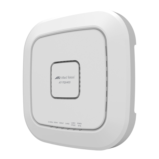
Chapter 1: Product Description Overview The AT-TQ5403 Series models are tri-band wireless access points designed connect wireless devices to your local area network. They are equipped with one PoE+ capable Ethernet port, a second Ethernet LAN port, a DC IN jack for an external power supply with a DC Power switch and a console port for manufacturing purposes only. - Page 21 AT-TQ5403 Series Wireless Access Point Installation Guide The top view of the AT-TQm5403 Access Point is illustrated in Figure 2. Back Edge Front Edge Figure 2. AT-TQm5403 Access Point Top View The front edge view of both access point models is illustrated in Figure 3.
- Page 22 Chapter 1: Product Description The back edge view of both access point models is illustrated in Figure 4. Kensington Ethernet DC Power Button Lock Port LAN1-POE+ LAN2 Console DC Input DC Input Reset Ports Serial Port Button Jack Jack Figure 4. Access Point Back Edge View Note The DC Power Button only controls power into the DC-IN jack only.
-
Page 23: Features
AT-TQ5403 Series Wireless Access Point Installation Guide Features This section lists the main features of both access point models. Hardware The hardware features are as follows: Features Triple radio is supported. The supported frequency ranges may vary depending on the region’s regulations. For example: - USA: 2.4GHz (2412-2462 MHz) -
Page 24: Management Access
Chapter 1: Product Description Five single color LED’s: LAN1 LAN2 2.4 GHz - 2.4 GHz radio band 5 GHz1 - W 52 and W 53 radio bands 5 GHz2 - W 56 radio band One dual color LED (i.e. Power LED) ... - Page 25 AT-TQ5403 Series Wireless Access Point Installation Guide Speed Both LAN ports can operate at 10/100 Mbps or 1000 Mbps. The speed is set automatically with Auto-Negotiation. You cannot disable Auto-Negotiation on the port. Note The LAN ports should be connected to network devices that also adjusts the speed with Auto-Negotiation.
-
Page 26: Redundant Power Supply
Chapter 1: Product Description Redundant Power Supply Both access point models offer a redundant power supply system. In addition to the power supply through the DC IN jack, the access point has one PoE+ capable LAN port (LAN1). The external power supply connected to the DC IN jack is the primary power source for the unit. -
Page 27: Leds
AT-TQ5403 Series Wireless Access Point Installation Guide LEDs The LEDs on the top panel display the status information. This LED display status information is given in Table 2. Table 2. LED Status Information State Description GREEN The access point is powered ON and operating normally. -
Page 28: Cable Specifications
Chapter 1: Product Description Cable Specifications Both access point models are connected to your local area network with Ethernet cables from Ethernet ports LAN1 and LAN2. Refer to “Cable Specifications” on page 50 for the specifications of these cables. -
Page 29: Wireless Access Point Installation
Chapter 2 Wireless Access Point Installation This chapter describes how to install the AT-TQ5403 or AT-TQm5403 Access Points. It contains the following sections: “Review Safety Precautions” on page 30 “Unpack Shipping Box Contents” on page 32 “Installation Guidelines” on page 33 ... -
Page 30: Review Safety Precautions
Chapter 2: Wireless Access Point Installation Review Safety Precautions Please review the following safety precautions before you begin to install the access point. Important: Safety statements that have the symbol are translated into multiple languages in the Translated Safety Statements document, which is available at www.alliedtelesis.com/library. - Page 31 AT-TQ5403 Series Wireless Access Point Installation Guide Warning This equipment shall be installed in a Restricted Access location. Warning FCC Caution: Any changes or modifications not expressly approved by the party responsible for compliance could void the user's authority to operate this equipment.
-
Page 32: Unpack Shipping Box Contents
Note Store the packaging material in a safe location so that if you need to return the unit to Allied Telesis, you will have the original shipping material available. 2. Verify that all components listed in Table 3 are included in your shipping box. -
Page 33: Installation Guidelines
AT-TQ5403 Series Wireless Access Point Installation Guide Installation Guidelines Review the following guidelines before installing the access point: • The ceiling or wall mounting surface must be of proper material to accommodate the screws and strong enough to support the weight of the access point and cables. -
Page 34: Install Access Point
Chapter 2: Wireless Access Point Installation Install Access Point This section contains the following topics: • ”General Installation Guidelines” • ”Table Top Installation” • “Ceiling or Wall - Mounting Bracket Installation” on page 35 • “Install Ethernet Cables and External DC Power Supply” on page 40 •... -
Page 35: Ceiling Or Wall - Mounting Bracket Installation
AT-TQ5403 Series Wireless Access Point Installation Guide 3. The installation of your access point on the table top surface is now complete. Ceiling or Wall - This section explains how to install the access point on a ceiling or wall that consists of a hard surface. - Page 36 Chapter 2: Wireless Access Point Installation Pre-Fit Mounting Bracket on Access Point To pre-fit the access point on the mounting bracket, perform the following procedure: 1. Install the two screws (provided) in the bottom side of the access point chassis. Refer to Figure 6. Figure 6.
- Page 37 AT-TQ5403 Series Wireless Access Point Installation Guide 3. Tighten the screws so that they touch the mounting bracket plate and then loosen them by approximately 1/4 turn. Note Adjust the access point chassis screws so they are loose enough to...
- Page 38 Chapter 2: Wireless Access Point Installation 2. Using the mounting bracket as a template, mark the two key-hole slots with a pencil in the location and orientation where you want to install the access point. Refer to the arrows in Figure 9. Ceiling Wall Figure 9.
- Page 39 AT-TQ5403 Series Wireless Access Point Installation Guide 5. Secure the physical position of the mounting bracket by pre-drilling holes through the two existing open bracket mounting holes in the opposite corners from the key-hole slots. Refer to the arrows in Figure 11.
-
Page 40: Install Ethernet Cables And External Dc Power Supply
Chapter 2: Wireless Access Point Installation Install Ethernet The Ethernet and power cables need to be connected before attaching the access point to the mounting bracket. Cables and External DC Note Power Supply Refer to “Cable Specifications” on page 50 when selecting Ethernet cables. -
Page 41: External Ac/Dc Power Adapter Installation
AC/DC power supply, proceed to ”External AC/DC Power Adapter Installation”. External AC/DC If you choose to use an external AC/DC power supply, Allied Telesis recommends that you procure an AT-MWS0091 Power Adapter by Power Adapter contacting your local Allied Telesis representative. -
Page 42: Install Anti-Theft Device
Note Anti-theft devices including a Kensington lock are not available from Allied Telesis. 1. Follow the instructions provided with the vendor’s anti-theft device packaging for the installation. Refer to Figure 17 for the Kensington lock port location. -
Page 43: Ceiling Or Wall - Attach Access Point To Mounting Bracket
AT-TQ5403 Series Wireless Access Point Installation Guide Ceiling or Wall - Perform this procedure to complete the ceiling or wall installation by attaching the chassis to the mounting bracket. Attach Access Point to 1. Align and insert the two access point chassis screws into the keyhole Mounting slots of the mounting bracket. - Page 44 Chapter 2: Wireless Access Point Installation 3. Tighten the bracket thumbscrew into the front of the chassis until it is securely fastened. Refer to Figure 20. Figure 20. Securely Fasten Chassis to Mounting Bracket with Thumbscrew 4. The ceiling or wall installation is now complete and your access point is ready for use.
-
Page 45: Start Initial Management Session
AT-TQ5403 Series Wireless Access Point Installation Guide Start Initial Management Session This section contains an abbreviated version of the procedure to start the initial management session. For complete instructions, refer to the AT-TQ5403 and AT-TQm5403 Management Software User’s Guide. The wireless access point firmware includes a DHCP client. The default setting for the client is enabled. - Page 46 Chapter 2: Wireless Access Point Installation...
-
Page 47: Technical Specifications
Appendix A Technical Specifications This appendix contains the specifications for the AT-TQ5403 and AT-TQm5403 access point models and the following sections: “Physical Specifications” “Environmental Specifications” “Power Specifications” on page 48 “Cable Specifications” on page 50 “LAN Port Specifications and Pinouts” on page 51 ... -
Page 48: Power Specifications
3000 m (9843 ft) Note Allied Telesis recommends using the AT-MWS0091 (WA-24Q12R) external AC/DC power supply with the AT-TQ5403 Series Access Point. This power supply is a UL Listed power supply and is fully compatible with the above specifications while meeting the standards of a separated extra-low voltage (SELV) product. -
Page 49: Poe+ Power Requirements
AT-TQ5403 Series Wireless Access Point Installation Guide PoE+ Power The access point power requirements for the LAN1 PoE+ port are given in Table 8. Requirements Table 8. PoE+ Power Requirements Parameter Specification AT-TQ5403 and AT-TQm5403 25.5 watts PoE Device Classification... -
Page 50: Cable Specifications
Appendix A: Technical Specifications Cable Specifications The access point Ethernet cable requirements for the LAN ports are listed in Table 9. Table 9. LAN Port Twisted Pair Cable Requirements 10Mbps 100Mbps 1000Mbps Cable Type PoE+ PoE+ PoE+ Standard TIA/EIA 568-A-compliant Category 5 shielded or unshielded cabling with 100 ohm impedance and 100 MHz frequency. -
Page 51: Lan Port Specifications And Pinouts
AT-TQ5403 Series Wireless Access Point Installation Guide LAN Port Specifications and Pinouts Port The access point port specifications are shown in Table 10. Specifications Table 10. LAN Port Specifications Connector Specification Standards - LAN1 and LAN2 IEEE 802.3 (10Base-T) IEEE 802.3u (100Base-TX) IEEE 802.3ab (1000Base-T) -
Page 52: Table 12. Mdi-X Pin Signals (10Base-T Or 100Base-Tx)
Appendix A: Technical Specifications Table 12 lists the pin signals for the MDI-X configuration at 10/100 Mbps. Table 12. MDI-X Pin Signals (10Base-T or 100Base-TX) Signal Table 13 lists the pin signals when the LAN port is operating at 1000 Mbps. -
Page 53: Regulatory Statements
Appendix B Regulatory Statements This appendix contains the following regulatory statements: “Federal Communication Commission Interference Statement” on page 54 “Industry Canada Statement” on page 56 “Europe - EU Declaration of Conformity” on page 58 ... -
Page 54: Federal Communication Commission Interference Statement
Appendix B: Regulatory Statements Federal Communication Commission Interference Statement This device complies with Part 15 of the FCC Rules. Operation is subject to the following two conditions: (1) This device may not cause harmful interference, and (2) this device must accept any interference received, including interference that may cause undesired operation. - Page 55 AT-TQ5403 Series Wireless Access Point Installation Guide Radiation Exposure Statement This equipment complies with FCC radiation exposure limits set forth for an uncontrolled environment. This equipment should be installed and operated with minimum distance 20 cm between the radiator & your body.
-
Page 56: Industry Canada Statement
Appendix B: Regulatory Statements Industry Canada Statement This device contains licence-exempt transmitter(s)/receiver(s) that comply with Innovation, Science and Economic Development Canada’s licence- exempt RSS(s). Operation is subject to the following two conditions: (1) This device may not cause interference. (2) This device must accept any interference, including interference that may cause undesired operation of the device. - Page 57 AT-TQ5403 Series Wireless Access Point Installation Guide Avertissement: Le guide d’utilisation des dispositifs pour réseaux locaux doit inclure des instructions précises sur les restrictions susmentionnées, notamment: (i) les dispositifs fonctionnant dans la bande 5150-5250 MHz sont réservés uniquement pour une utilisation à l’intérieur afin de réduire les risques de brouillage préjudiciable aux systèmes de satellites mobiles...
-
Page 58: Europe - Eu Declaration Of Conformity
20 cm between Statement the radiator and your body. Importer Allied Telesis International BV Incheonweg 7, 1437 EK Rozenburg Note Contact Allied Telesis for the EU conformity statement. To contact Allied Telesis, visit our web site at www.alliedtelesis.com/contact.
Need help?
Do you have a question about the AT-TQ5403 Series and is the answer not in the manual?
Questions and answers