Table of Contents
Advertisement
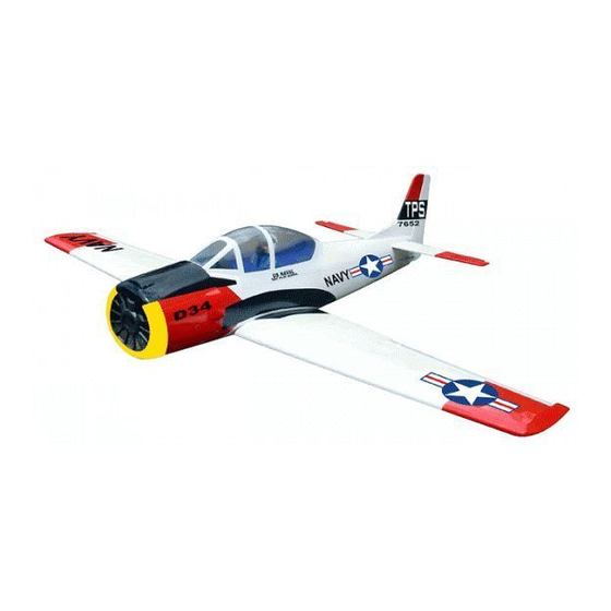
Instruction Manual book
SPECIFICATION
Wingspan
Length
Weight
Radio
Servo
Glow Engine : 61 cu.in
:
163 cm
64.17 inches.
: 130 cm
51.18 inches.
: 3.3kg
7.26 lbs.
:
5 channels.
:
7 servos.
91 cu.in
ITEM CODE: BH45.
2 stroke.
4 stroke.
Made in Vietnam.
Advertisement
Table of Contents

Related Manuals for Black Horse Model T-28 TROJAN


Summary of Contents for Black Horse Model T-28 TROJAN
- Page 1 Instruction Manual book ITEM CODE: BH45. SPECIFICATION Wingspan 163 cm 64.17 inches. Length : 130 cm 51.18 inches. Weight : 3.3kg 7.26 lbs. Radio 5 channels.
-
Page 2: Parts List
TROJAN. Instruction Manual This instruction manual is designed to help you build a great flying aeroplane. Please read this manual thoroughly before starting assembly of your TROJAN. Use the parts listing below to identify all parts. WARNING. Please be aware that this aeroplane is not a toy and if assembled or used incorrectly it is capable of causing injury to people or property. -
Page 3: Safety Precaution
TROJAN. INSTRUCTION MANUAL Caution: this model is not a toy! SAFETY PRECAUTION. If you are a beginner to this type of powered + This is not a toy model, please ask an experienced model flyer + Be sure that no other flyers are using your for help and support. -
Page 4: Instruction Manual
TROJAN. Instruction Manual INSTALLING THE AILERON- FLAP SERVOS. 1. Install the rubber grommets and brass eyelets onto the aileron and flap servo. C/A glue C/A glue C/A glue Bottom side. C/A glue Flap. Aileron. Servo tray. - Page 5 TROJAN. INSTRUCTION MANUAL 5. Instal servo tray with aileron servo into the wing as same as picture below. 3. Drill 1,5mm pilot holes through the block of wood for each of the four mounting screws provided with the servo. Install servo into aileron Aileron.
- Page 6 TROJAN. Instruction Manual Aileron. Flap. aileron control horn Flap. Remove covering Repeat the procedure for the other wing half. INSTALLING THE AILERON - FLAP SERVO CONTROL HORN. 1. Using a ruler & pen to draw a straight line as below picture. 3 x 40mm.
-
Page 7: Installing The Aileron Linkages
TROJAN. INSTRUCTION MANUAL 2. Install control horn as same as picture Flap 4. Install control horn as same as the below. way of aileron control horn. control horn. Flap. aileron 3. Install control horn as same as picture below. - Page 8 TROJAN. Instruction Manual Aileron. Cut. Aileron. 4. Locate one nylon servo arm, and using wire cutters,remove all but one of the arms. Using a 2mm drill bit, enlarge the third hole out from the center of the arm to accommodate the aileron pushrod wire.
-
Page 9: Joining The Wing Halves
TROJAN. INSTRUCTION MANUAL Aileron Flap servo. servo. finishing Bottom side Top side. Flap. Aileron. JOINING THE WING HALVES. 1. Location the aluminium wing dihedral brace. 2. Using a modeling knife, remove the cov- ering wing. Epoxy glue. Remove covering. Aluminium brace. - Page 10 TROJAN. Instruction Manual Masking tape. Mark point. Apply masking tape. Wing bolt plate...
-
Page 11: Installing Landing Gear
TROJAN. INSTRUCTION MANUAL INSTALLING LANDING GEAR. See pictures below: 3x12mm. Mark point 1mm drill bit. Remove covering. -
Page 12: Engine Mount
TROJAN. Instruction Manual ENGINE MOUNT. See pictures below: 3.5x25mm. 4x 30mm. -
Page 13: Installing The Stopper Assembly
TROJAN. INSTRUCTION MANUAL FUEL TANK. INSTALLING THE STOPPER ASSEMBLY 1. The stopper has been pre-assembled at the factory. 2. Using a modeling knife, cut one length of silicon fuel line (the length of silicon fuel line is calculated by how the weighted clunk should rest about 8mm away from the rear of the tank and move freely inside the tank). - Page 14 TROJAN. Instruction Manual 8. Feed three lines through the fuel tank compartment and through the pre-drilled hole in the firewall. Pull the lines out from behind the engine, while guiding the fuel tank into place. Push the fuel tank as far forward as possible, the front of the tank should just about touch the back of the firewall.
-
Page 15: Installing The Engine
TROJAN. INSTRUCTION MANUAL INSTALLING THE ENGINE. Locate the long piece of wire used for the throttle pushrod. One end of the wire has been pre-bend in to a “Z” bend at the factory. This “Z” bend should be inserted into the throttle arm of the engine when the engine is fitted onto the engine mount. -
Page 16: Installing The Nose Gear
TROJAN. Instruction Manual INSTALLING THE NOSE GEAR. - Page 17 TROJAN. INSTRUCTION MANUAL COWLING. 1. Slide the fiberglass cowl over the en- gine and line up the back edge of the cowl with the marks you made on the fuselage. Trim and cut. Trim and cut.
- Page 18 TROJAN. Instruction Manual 2. While keeping the back edge of the cowl flush with the marks, align the front of 3 x 10mm. the cowl with the crankshaft of the engine. The front of the cowl should be positioned so the crankshaft is in nearly the middle of the cowl opening.
-
Page 19: Elevator Installation
TROJAN. INSTRUCTION MANUAL HORIZONTAL STABILIZER INSTALLATION. ELEVATOR INSTALLATION. 1. Using a modeling knife, cut away the covering from the fuselage for the stabilizer SERVO INSTALLATION. and remove it. 1. Install the rubber grommets and brass collets into the elevator servo. Test fit the servo into the servo tray. - Page 20 TROJAN. Instruction Manual 3. Mark the shape of the vertical on the left and right sides onto the horizontal stabilizer using a left-tip pen. C/A glue Pen. Bottom side. 4. Remove the stabilizer. Using the lines C/A glue you just drew as a guide, carefully remove the covering from between them using a modeling knife.
-
Page 21: Elevator Control Horn Installa- Tion
TROJAN. INSTRUCTION MANUAL 6. After the epoxy has fully cured, Check to mark sure the wing and stabi- remove lizer are paralell. If they are not, lightly sand the masking tape or T-pins used to hold the the opening in the fuselage for the stabilizer stabilizer in place and carefully inspect the until the stabilizer is paralell to the wing. -
Page 22: Elevator Pushrod Installation
TROJAN. Instruction Manual Elevator control horn. ELEVATOR PUSHROD INSTALLATION. Pushrod install as same as method of pushrod wing. See pictures below: C/A glue. Bottom side . C/A glue. - Page 23 TROJAN. INSTRUCTION MANUAL Elevator servo. Elevator Elevator Bend pushrod. pushrod. Cut. Cut.
-
Page 24: Vertical Stabilizer
TROJAN. Instruction Manual C/A glue C/A glue VERTICAL STABILIZER. C/A glue Vertical stabilizer installation See picture below. C/A glue... - Page 25 TROJAN. INSTRUCTION MANUAL Remove covering. Hinge. 1. Using a modeling knife cut away the covering from the end of fuselage for the rud- der hinge. Remove covering. Top side. Hinge slot. 5. Put the vertical stabilizer back in place.
-
Page 26: Rudder Control Horn Installa- Tion
TROJAN. Instruction Manual 6) When you are sure that everything is a Epoxy glue. aligned correctly, mix up a generous amount of 30 minute epoxy. Apply a thin layer to the slot in the mounting platform and to the verti- cal stabilizer mounting area. -
Page 27: Rudder Pushrod Installation
TROJAN. INSTRUCTION MANUAL Rudder control horn RUDDER PUSHROD INSTALLATION. Bend and cut after Rudder pushrod install as same as the way of aileron pushrod. Rudder pushrod. Rudder pushrod Elevator pushrod Rudder servo. Connector... - Page 28 TROJAN. Instruction Manual Elevator pushdrod Elevator pushdrod Rudder pushdrod Cut. C/A glue...
-
Page 29: Installing The Switch
TROJAN. INSTRUCTION MANUAL Secure. Throttle pushrod. Cut. Nose gear pushrod Rudder pushrod. Cut. Rudder pushrod. Nose gear pushrod Elevator pushrod. E l e v a t o r pushrod. Throttle pushrod. INSTALLING THE SWITCH. 1) Cut out the switch hole using a modeling knife. - Page 30 TROJAN. Instruction Manual Tie wrap. Tie wrap. Battery. Rubber band. Switch. INSTALLING THE RECEIVER AND BATTERY. 1. Plug the servo leads and the switch lead into the receiver. You may want to plug an aileron extension into the receiver to make plugging in the aileron servo lead easier when you are installing the wing .
-
Page 31: Wing Attachment
TROJAN. INSTRUCTION MANUAL Receiver. Secure. WING ATTACHMENT. See picture wing attach to fuselage. Wing bolt. Installing the fuselage hatch as same as picture below. - Page 32 TROJAN. Instruction Manual BALANCING. 1. It is critical that your airplane be bal- anced correctly. Improper balance will cause your plane to lose control and crash. THE CENTER OF GRAVITY IS LOCATED 100mm BACK FROM THE LEADING EDGE OF THE WING.
-
Page 33: Control Throws
TROJAN. INSTRUCTION MANUAL CONTROL THROWS. 1. We highly recommend setting up a plane using the control throws listed. 2. The control throws should be measured at the widest point of each control surface. ... - Page 34 TROJAN. Instruction Manual...
Need help?
Do you have a question about the T-28 TROJAN and is the answer not in the manual?
Questions and answers