Table of Contents
Advertisement
Quick Links
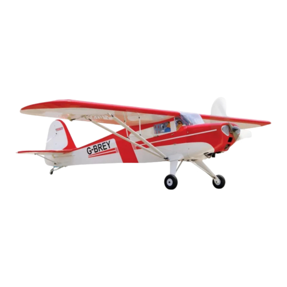
SPECIFICATION
Wingspan :
Length
Weight
Parts listing required (not included).
Radio
Servo
Engine
Instruction Manual book
2,050 mm
:
1,530 mm
:
5,9 kg
:
05 channels.
:
06 servos.
:
O.S.GT 22cc Gas.
80.71 in.
60.24 in.
12.98Lbs.
Made in Vietnam.
ITEM CODE:BH 134
Advertisement
Table of Contents

Subscribe to Our Youtube Channel
Related Manuals for Black Horse Model TAYLORCRAFT


Summary of Contents for Black Horse Model TAYLORCRAFT
- Page 1 Instruction Manual book ITEM CODE:BH 134 SPECIFICATION Wingspan : 2,050 mm 80.71 in. Length 1,530 mm 60.24 in. Weight 5,9 kg 12.98Lbs. Parts listing required (not included). ...
-
Page 2: Parts List
Instruction Manual - Item code: BH 134 This instruction manual is designed to help you build a great flying aeroplane. Please read this manual thoroughly before starting assembly of your TAYLORCRAFT. Use the parts listing below to identify all parts. WARNING. -
Page 3: Safety Precaution
TAYLORCRAFT Instruction Manual - Item code: BH 134 Wing warp: Hold the panel twisted Caution: this model is not a toy! gently in the opposite If you are a beginner to this type of powered direction to the warp, and... -
Page 4: Installing The Aileron Servo
TAYLORCRAFT Instruction Manual - Item code: BH 134 REPLACEMENT SMALL PARTS I. SERVO 1. Aluminium landing gear.(1a,1b) 1.INSTALLING THE AILERON SERVO. 2. Wheels. 1. Install the rubber grommets and brass eyelets onto the aileron servo. 3.Plastic parts for landing gear. - Page 5 TAYLORCRAFT Instruction Manual - Item code: BH 134 2. Using a modeling knife, remove the cov- ering servo tray. Electric wire. Servo tray. Thread. Remove covering Servo tray. 5. Instal servo tray with aileron servo into the wing as same as picture below.
-
Page 6: Installing The Aileron Linkages
TAYLORCRAFT Instruction Manual - Item code: BH 134 Install aileron control horn as same 3.INSTALLING THE AILERON as picture below. LINKAGES . Installing the aileron linkages as pictures below. M3 lock nut. A+B Epoxy 75mm PLUS 3x10mm Attach the clevis to the outer hole in the control horn. -
Page 7: Wing Struts Installation
TAYLORCRAFT Instruction Manual - Item code: BH 134 WING STRUTS INSTALLATION 4x12mm Secure 3x8mm Bottom side Secure. Aileron Repeat the procedure for the other wing half. - Page 8 TAYLORCRAFT Instruction Manual - Item code: BH 134 Secure. 86mm 3 x 8 m m 3 x 8 m m 92mm 3 x 8 m m bend 90 degree. S e c u r e . bend 90 d e g r e e Secure.
- Page 9 TAYLORCRAFT Instruction Manual - Item code: BH 134 Secure bend 80 3x10mm. degree. bend 80 d e g r e e Secure 3x8mm. Secure 3x8mm. 3 x 8 m m 3x10mm Bottom side Secure 3x10mm. Bottom side Secure 3x8mm.
-
Page 10: Installing The Engine Mount
TAYLORCRAFT Instruction Manual - Item code: BH 134 INSTALLING THE ENGINE MOUNT. INSTALLING THE ENGINE MOUNT. See pictures below: 4x 30mm 4x 30mm INSTALLING THE ENGINE. Locate the long piece of wire used for the throttle pushrod. One end of the wire has been pre-bend in to a “Z”... - Page 11 TAYLORCRAFT Instruction Manual - Item code: BH 134 Drill a hole 4mm diameter. Pushrod choke. Pushrod choke.
-
Page 12: Installing The Stopper Assembly
TAYLORCRAFT Instruction Manual - Item code: BH 134 4. Carefully bend the third nylon tube down at a 45 degree angle (using a cigarette lighter). This tube will be vent tube to the fueling valve. Pushrod choke. When the stopper assembly is installed in the tank, the top of the vent tube should rest just below the top surface of the tank. - Page 13 TAYLORCRAFT Instruction Manual - Item code: BH 134 Do not secure the tank into place perma- 6. When satisfied with the alignment of the nently until after balancing the airplane. stopper assembly tighten the 3mm x 20mm You may need to remove the tank to mount machine screw until the rubber stopper ex- the battery in the fuel tank compartment.
- Page 14 TAYLORCRAFT Instruction Manual - Item code: BH 134 INSTALLING THE THROTTLE PUSHROD. 1. Install one adjustable metal connector through the third hole out from the center of one servo arm, enlarge the hole in the servo arm using a 2mm drill bit to accommodate the servo connector.
- Page 15 TAYLORCRAFT Instruction Manual - Item code: BH 134 Trim and cut C/A glue. COWLING. 1. Slide the fiberglass cowl over the en- gine and line up the back edge of the cowl with Right side. the marks you made on the fuselage.
- Page 16 TAYLORCRAFT Instruction Manual - Item code: BH 134 Front view Drill a hole 2.5mm diameter ELEVATOR INSTALLATION SERVO INSTALLATION 3 x 12mm 1. Install the rubber grommets and brass collets into the elevator servo. Test fit the servo into the servo tray.
-
Page 17: Elevator Control Horn Installation
TAYLORCRAFT Instruction Manual - Item code: BH 134 4x12mm Throttle servo Secure Elevator servo Elevator servo ELEVATOR CONTROL HORN INSTALLATION. HORIZONTAL STABILIZER. Elevator control horn install as same as the Horizontal stabilizer installation way of aileron control horn. See picture below Control horn of Elevator. - Page 18 TAYLORCRAFT Instruction Manual - Item code: BH 134 Control horn of elevator. Bottom side. 9 mm 243 mm Control horn of elevator.
-
Page 19: Elevator Pushrod Installation
TAYLORCRAFT Instruction Manual - Item code: BH 134 E l e v a t o r E l e v a t o r pushrod. pushrod. Bottom side. Elevator servo. Elevator servo. Throttle servo Bottom side. ELEVATOR PUSHROD INSTALLATION. Elevator pushrod install as same as the way of aileron pushrod. -
Page 20: Rudder Servo Installation
TAYLORCRAFT Instruction Manual - Item code: BH 134 1. Put the rudder into the fuselage as same RUDDER SERVO INSTALLATION. as picture below. Rudder servo install as same as method of elevator servo. See picture below: Rudder servo. Rudder servo. -
Page 21: Rudder Cable Installation
TAYLORCRAFT Instruction Manual - Item code: BH 134 A+ B Epoxy PLUS glue. Rudder control horn. RUDDER CABLE INSTALLATION. 1. Rudder push - pull system install as RUDDER CONTROL HORN same as picture below. INSTALLATION. Rudder control horn install as same as the 3x 10 mm way of aileron control horn. -
Page 22: Mounting The Tail Wheel Bracket
TAYLORCRAFT Instruction Manual - Item code: BH 134 Drill a hole Rudder pushrod MOUNTING THE TAIL WHEEL BRACKET. 1) Set the tail wheel assembly in place on the plywood plate. The pivot point of the... - Page 23 TAYLORCRAFT Instruction Manual - Item code: BH 134 Vertical Stabilizer Struts. 3x8mm 3x25mm Bottom side. 3x8mm Secure.
- Page 24 TAYLORCRAFT Instruction Manual - Item code: BH 134 3x25mm 3 x 8 m m . S e c u r e Secure. 3x25mm. 3x25mm Bottom side. Top side.
- Page 25 TAYLORCRAFT Instruction Manual - Item code: BH 134 Plastic parts for elevator pushrod and rudder cable. Top side. Bottom side. C/A glue. S e c u r e 3x25mm. Bottom side. Bottom side. Top side.
- Page 26 TAYLORCRAFT Instruction Manual - Item code: BH 134 MAIN GEAR INSTALATION. Landing gear PARTS REQUIRED 1) Assemble and mounting the wheel pants as shown in the following pictures. 2) Using the hardware provided, mount the 5x40mm main landing gear to the fuselage.
- Page 27 TAYLORCRAFT Instruction Manual - Item code: BH 134 Mark line. 4x12mm Remove covering. Secure Epoxy glue. C/A glue. 3x10mm. 4x6mm. 4x12mm...
- Page 28 TAYLORCRAFT Instruction Manual - Item code: BH 134 3x10mm Secure 3x10mm 4x6mm. Secure. Secure Bottom side. 5x40mm.
-
Page 29: Installing The Switch
TAYLORCRAFT Instruction Manual - Item code: BH 134 INSTALLING THE RECEIVER AND BATTERY. Bottom side. 1. Plug the servo leads and the switch lead into the receiver. You may want to plug an aileron extension into the receiver to make plugging in the aileron servo lead easier when you are installing the wing . - Page 30 TAYLORCRAFT Instruction Manual - Item code: BH 134 INSTALLING THE COCKPIT. See pictures below: A+B Epoxy Right side. PLUS glue. Secure. A+B Epoxy PLUS glue.
-
Page 31: Wing Attachment
TAYLORCRAFT Instruction Manual - Item code: BH 134 WING ATTACHMENT. Locate the aluminium wing dihedral brace. aluminium 19mm 705 mm. *** Test fit the aluminium tube dihedral brace into each wing haft. The brace should slide in easily. If not, use 220 grit sand around the edges and ends of the brace until it fits prop- erly. - Page 32 TAYLORCRAFT Instruction Manual - Item code: BH 134 Top side. Left side. Right side. 3x15mm. Secure.
-
Page 33: Control Throws
TAYLORCRAFT Instruction Manual - Item code: BH 134 BALANCING. CONTROL THROWS. 1) It is critical that your airplane be bal- 1) We highly recommend setting up a anced correctly. Improper balance will cause plane using the control throws listed.
Need help?
Do you have a question about the TAYLORCRAFT and is the answer not in the manual?
Questions and answers