Table of Contents

Subscribe to Our Youtube Channel
Related Manuals for Black Horse Model TWISTER


Summary of Contents for Black Horse Model TWISTER
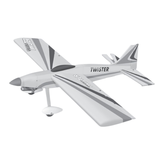
- Page 1 Instruction Manual book SPECIFICATION Wingspan : 1,380 mm 54.3 in. Length 1,100 mm 43.3 in. Weight 2.15 kg 4.73 Lbs. Radio 04 channels. Servo 05 servos. Engine 32-40 Cu. in 2 stroke. 52 Cu. in 4 stroke. Made in Vietnam.
- Page 2 TWISTER Instruction Manual This instruction manual is designed to help you build a great flying aeroplane. Please read this manual thoroughly before starting assembly of your TWISTER. Use the parts listing below to identify all parts. WARNING Please be aware that this aeroplane is not a toy and if assembled or used incorrectly it is capable of causing injury to people or property.
-
Page 3: Safety Precaution
TWISTER. INSTRUCTION MANUAL Caution: this model is not a toy! SAFETY PRECAUTION. If you are a beginner to this type of powered + This is not a toy model, please ask an experienced model flyer + Be sure that no other flyers are using your for help and support. -
Page 4: Installing The Aileron Servos
TWISTER Instruction Manual 3. Drill 1,5mm pilot holes through the block INSTALLING THE AILERON SERVOS. of wood for each of the four mounting screws provided with the servo. Install servo into ai- 1. Install the rubber grommets and brass leron servo tray as same as picture below. - Page 5 TWISTER. INSTRUCTION MANUAL 5. Instal servo tray with aileron servo into the wing as same as picture below. Thread Servo tray Aileron Control horn 1. Using a ruler & pen to draw a straight 2 x 10 mm. line as below picture.
-
Page 6: Installing The Aileron Linkages
TWISTER Instruction Manual Remove covering Bottom side Top side 3) Install control horn as same as picture below. INSTALLING THE AILERON LINKAGES 1. Working with the aileron linkage for now, thread one nylon clevis onto one of the threaded wires. -
Page 7: Joining The Wing Halves
TWISTER. INSTRUCTION MANUAL JOINING THE WING HALVES 1. Locate the aluminium wing dihedral brace. Using a ruler, locate its centre and draw a vertical line . Bend and cut after 2. Using a modeling knife, remove the cov- ering wing. - Page 8 TWISTER Instruction Manual Apply epoxy to Bottom side these areas. 3. Mix a generous amount of 30 minute epoxy. Coat the exposed half of the dihedral brace, and the remaining wing joiner box and both root ribs with epoxy. Slide the two wing halves together and carefully align them at the leading and trailing edges.
-
Page 9: Installing The Stopper Assembly
TWISTER. INSTRUCTION MANUAL When the stopper assembly is installed in the tank, the top of the vent tube should rest just below the top surface of the tank. It should not touch the top of the tank. 3 x 25mm. - Page 10 TWISTER Instruction Manual Tank brace C/A glue Blow through one of the lines to ensure the fuel lines have not become kinked inside the fuel tank compartment. Air should flow through easily. 9. To secure the fuel tank in place, apply a...
- Page 11 TWISTER. INSTRUCTION MANUAL Mart point Pushrod wire 3x 20mm COWLING 1) Slide the fiberglass cowl over the en- gine and line up the back edge of the cowl with the marks you made on the fuselage. Trim and cut...
- Page 12 TWISTER Instruction Manual Slide the cowl back over the engine and secure it in place using four wood screws.See picture below. 3 x 10mm Machine screw. 2) While keeping the back edge of the cowl flush with the marks, align the front of the cowl with the crankshaft of the engine.
-
Page 13: Installing The Spinner
TWISTER. INSTRUCTION MANUAL 4) Install the muffler and muffler extension ELEVATOR INSTALLATION. onto the engine and make the cutout in the cowl for muffler clearance. Connect the fuel SERVO INSTALLATION. and pressure lines to the carburetor, muffler and fuel filler valve. - Page 14 TWISTER Instruction Manual Mark point Top side Top side Bottom side Bottom side 5) When you are sure that everything is aligned correctly, mix up a generous amount 3) Mark the shape of the vertical on the of 30 minute epoxy. Apply a thin layer to the...
-
Page 15: Elevator Control Horn Installa- Tion
TWISTER. INSTRUCTION MANUAL C/A glue Drill a hole with 6mm (diameter) 6) After the epoxy has fully cured, re- move the masking tape or T-pins used to hold the stabilizer in place and carefully inspect the glue joints. Use more epoxy to fill in any... -
Page 16: Elevator Pushrod Installation
TWISTER Instruction Manual ELEVATOR PUSHROD INSTALLATION. Bend and cut after Elevator pushrod Bottom side Elevator servo Top side... -
Page 17: Vertical Installation
TWISTER. INSTRUCTION MANUAL 3) Mark the shape of the vertical on the left VERTICAL INSTALLATION and right side on the rudder using a felt-tip pen. Mark point Rudder servo 4) Now, remove the rudder and using a modeling knife, carefully cut just inside the marked lines and remove the film of the rudder. -
Page 18: Rudder Control Horn Installa- Tion
TWISTER Instruction Manual RUDDER CONTROL HORN INSTALLA- TION. Rudder control horn install as same as the way of aileron control horn. Please see pic- tures below. Epoxy glue Nilon M3 lock nut control clasp. 3mm x 40mm. Control horn of Rudder. -
Page 19: Rudder Pushrod Installation
TWISTER. INSTRUCTION MANUAL E l e v a t o r pushrod Rudder pushrod C/A glue RUDDER PUSHROD INSTALLATION. Bend and cut after Elevator servo Rudder servo... -
Page 20: Installing The Throttle Pushrod
TWISTER Instruction Manual INSTALLING THE THROTTLE PUSHROD 1) Install one adjustable metal connector through the third hole out from the center of one servo arm, enlarge the hole in the servo arm using a 2mm drill bit to accommodate the servo connector. Remove the excess material from the arm. -
Page 21: Installing The Receiver And Battery
TWISTER. INSTRUCTION MANUAL switch Battery Receiver INSTALLING THE RECEIVER AND BATTERY. 1. Plug the servo leads and the switch lead into the receiver. You may want to plug an aileron extension into the receiver to make plugging in the aileron servo lead easier when you are installing the wing . -
Page 22: Installing The Main Landing Gear
TWISTER Instruction Manual 2) A drop of C/A glue on the wheel collar 1) Assemble and mounting the wheel pants screws will help keep them from coming lose as shown in the following pictures. during operation. Repeat the process for the other wheel. -
Page 23: Mounting The Tail Wheel Bracket
TWISTER. INSTRUCTION MANUAL MOUNTING THE TAIL WHEEL BRACKET 1) Set the tail wheel assembly in place on the plywood plate. The pivot point of the tail wheel wire should be even with the rudder hinge line and the tail wheel bracket should be centered on the plywood plate. - Page 24 TWISTER Instruction Manual Top side Bottom side Wing bolt. Secure...
-
Page 25: Control Throws
5. Check the receiver antenna . It should be fully extended and not coiled up inside the fuselage. 90 MM 6. Properly balance the propeller. We wish you many safe and enjoyable flights with your TWISTER.
Need help?
Do you have a question about the TWISTER and is the answer not in the manual?
Questions and answers