Subscribe to Our Youtube Channel
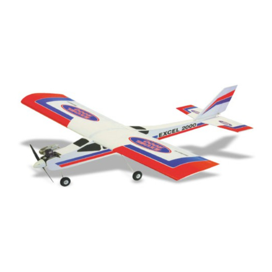
Summary of Contents for Black Horse Model EXCEL 2000
- Page 1 Instruction Manual book SPECIFICATION Wingspan : 1,530 mm 60.24 in. Length 1,340 mm 52.76 in. Weight 2.5 kg 5.5 Lbs. Radio 04 channels. Servo 04 servos. Engine 40-46 2 stroke 4 stroke Made in Vietnam.
-
Page 2: Parts List
EXCEL 2000. This instruction manual is designed to help you build a great flying aeroplane. Please read this manual thoroughly before starting assembly of your EXCEL 2000. Use the parts listing below to identify all parts. WARNING. Please be aware that this aeroplane is not a toy and if assembled or used incorrectly it is capable of causing injury to people or property. -
Page 3: Safety Precaution
Instruction Manual. SAFETY PRECAUTION. SERVO INSTALLATION. + This is not a toy + Be sure that no other flyers are using your radio frequency. + Wear safety glasses. + Keep loose clothing and wires away from the propeller. + Do not start the engine if people are near. Do not stand in line with the side of the propeller. - Page 4 EXCEL 2000. Epoxy glue. 2) Place the mount onto the wing haft, aligning the cutout in the mount with the cut- out in the wing. The two notches in the mount should face the leading edge of the wing. 3) While holding the servo mount firmly in place, trace around it using a pen.
-
Page 5: Wing Assembly
Instruction Manual. WING ASSEMBLY. Masking tape. 1) Location the aluminium wing dihedral brace. 2) Test fit the dihedral brace into each wing half. The brace should slide in easily. If not, use 220 grit sandpaper with a sanding block and sand down the edges and ends of the brace until it fits properly. -
Page 6: Installing The Engine Mount
EXCEL 2000. FUEL TANK. Cut. INSTALLING THE STOPPER ASSEMBLY 1) The stopper has been pre-assembled at the factory. 2) Using a modeling knife, cut one length of silicon fuel line (the length of silicon fuel line is calculated by how the weighted clunk should rest about 8mm away from the rear of the tank and move freely inside the tank). -
Page 7: Installing The Engine
Instruction Manual. 5) Test fit the stopper assembly into the Fuel tank. tank. It may be necessary to remove some of the flashing around the tank opening using a modeling knife. If flashing is present, make sure none of it falls into the tank. 6) When satisfied with the alignment of the stopper assembly tighten the 3mm x 20mm machine screw until the rubber stopper... -
Page 8: Nose Gear Installation
EXCEL 2000. NOSE GEAR INSTALLATION. Installing steering arm as follow Steering arm. Adjust the nose gear steering arm until the arm is parallel with the fire wall. -
Page 9: Main Gear Installation
Instruction Manual. MAIN GEAR INSTALLATION. Steering arm. INSTALLING THE SPINNER. Install the spinner backplate, propeller and spinner cone. The spinner cone is held in place using two 3mm x 12mm wood screws. 1) Using a modeling knife, remove the covering from over the two main gear mounting slots located in the bottom of the fuselage. -
Page 10: Elevator Servo Installation
EXCEL 2000. Center line. The top of the stabilizer does not have the hinge pins exposed. 2) Using a modeling knife, carefully remove the covering from over the vertical stabilizer mounting slot in the top of the fuselage. Remove covering. - Page 11 Instruction Manual. Remove covering. C/A glue. Top side. 6) After the epoxy has fully cured, remove the masking tape or T-pins used to hold the stabilizer in place. Carefully inspect the glue joints. Use more epoxy to fill in any gaps that may exist that were not filled previously and clean up the excess using a paper towel and rubbing alcohol.
- Page 12 EXCEL 2000. Drill hold. Elevator pushrod. Cut. Elevator control horn.
-
Page 13: Vertical Stabilizer Installation
Instruction Manual. Elevator servo. Pen. 3) Remove the vertical stabilizer. Using a modeling knife, remove the covering from below the lines you drew. Also remove the VERTICAL STABILIZER INSTALLATION. covering from the bottom edge of the stabi- lizer and the bottom and top edges of the filler block. - Page 14 EXCEL 2000. Rudder control horn. Vertical Stabilizer. Horizontal 90º Stabilizer. 5) When you are sure that everything is Rudder pushrod. aligned correctly, mix up a generous amount of Flash 30 Minute Epoxy. Apply a thin layer to the mounting slot in the top of the fuselage and to the sides and bottom of the vertical stabilizer mounting area.
-
Page 15: Installing The Switch
Instruction Manual. INSTALLING THE RECEIVER AND BATTERY. Elevator 1) Plug the servo leads and the switch servo. lead into the receiver. Plug the battery pack lead into the switch. 2) Wrap the receiver and battery pack in Throttle the protective foam to protect them from servo. -
Page 16: Control Throws
EXCEL 2000. finishing Receiver. Tie wrap. BALANCING. 1) It is critical that your airplane be balanced correctly. Improper balance will cause your plane to lose control and crash. THE CENTER OF GRAVITY IS LOCATED 90mm BACK FROM THE LEADING EDGE OF THE WING. -
Page 17: Pre-Flight Check
Instruction Manual. Aileron Control PRE-FLIGHT CHECK. 1) Completely charge your transmitter and receiver batteries before your first day of flying. 2) Check every bolt and every glue joint in your plane to ensure that everything is tight and well bonded. 3) Double check the balance of the airplane.


Need help?
Do you have a question about the EXCEL 2000 and is the answer not in the manual?
Questions and answers