Black Horse Model CHIPMUNK Instruction Manual
Hide thumbs
Also See for CHIPMUNK:
- Instruction manual book (39 pages) ,
- Instruction manual book (39 pages)
Table of Contents
Advertisement
Quick Links
Instruction Manual Book
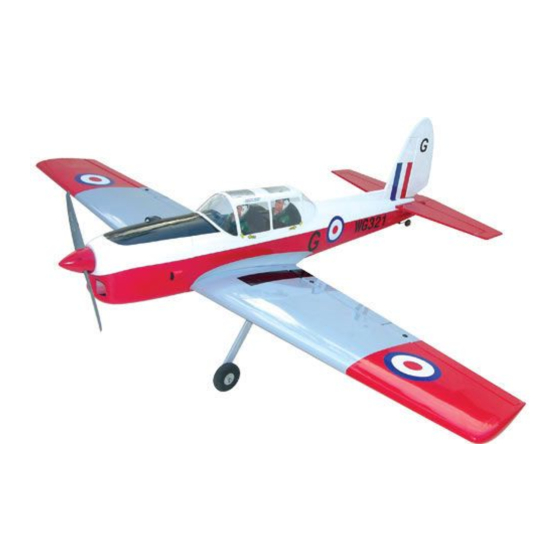
ITEM CODE: BH63-A.
SPECIFICATION
Wingspan : 2,170 mm
85.43 in.
Length
: 1,740 mm
68.50 in.
Weight
: 6.6 kg
14.52 lbs.
Parts listing required (not included):
Radio
: 06 channels.
Servo
: 08 standard high torque servos.
Engine
: O.S GT 33CC - 45CC Gas.
Made in Vietnam.
Advertisement
Table of Contents

Related Manuals for Black Horse Model CHIPMUNK


Summary of Contents for Black Horse Model CHIPMUNK
- Page 1 Instruction Manual Book ITEM CODE: BH63-A. SPECIFICATION Wingspan : 2,170 mm 85.43 in. Length : 1,740 mm 68.50 in. Weight : 6.6 kg 14.52 lbs. Parts listing required (not included): Radio : 06 channels. Servo : 08 standard high torque servos.
- Page 2 INSTRUCTION MANUAL ITEM CODE: BH63-A This instruction manual is designed to help you build a great flying aeroplane. Please read this manual thoroughly before starting assembly of your CHIPMUNK. Use the parts listing below to identify all parts. WARNING Please be aware that this aeroplane is not a toy and if assembled or used incorrectly it is capable of causing injury to people or property.
-
Page 3: Safety Precaution
CHIPMUNK INSTRUCTION MANUAL ITEM CODE: BH63-A Caution: this model is not a toy! If you are a beginner to this type of powered model, please ask an experienced model flyer for help and support. If you attempt to operate the model without knowing what you are doing you could easily injure yourself or somebody else. - Page 4 CHIPMUNK INSTRUCTION MANUAL ITEM CODE: BH63-A REPLACEMENT LARGE PARTS E. Aluminium tube wing dihedral brace. A. Cowling. F. Aluminium tube for B. Wing panel (B1& B2). Horizontal stabilizer. C. Fuselage. G. Decal sheets. D. Horizontal stabilizer. REPLACEMENT SMALL PARTS 3x12mm...
-
Page 5: Installing The Aileron Servos
CHIPMUNK INSTRUCTION MANUAL ITEM CODE: BH63-A INSTALLING THE AILERON SERVOS. 1. Install the rubber grommets and brass eyelets onto the aileron and flap servo. Top side Bottom side 3. Drill 1,5mm pilot holes through the block of wood for each of the four mounting screws provided with the servo. -
Page 6: Installing The Aileron Linkages
CHIPMUNK INSTRUCTION MANUAL ITEM CODE: BH63-A 5. Instal servo tray with aileron servo into the wing as same as picture below. 2x10mm. Control horn of the aileron. Secure. Repeat the procedure for the other wing half. INSTALLING THE AILERON LINKAGES. -
Page 7: Installing The Flap Servos
CHIPMUNK INSTRUCTION MANUAL ITEM CODE: BH63-A Aileron. Repeat the procedure for the other wing half. 2x10mm. II. FLAP. 1.INSTALLING THE FLAP SERVOS. Secure. Bottom side. Flap 2.INSTALLING THE FLAP CONTROL HORN. Flap control horn... - Page 8 CHIPMUNK INSTRUCTION MANUAL ITEM CODE: BH63-A A+B Epoxy Secure PLUS glue 4x12mm Flap control horn 3. INSTALLING THE FLAP LINKAGES. Installing the flap linkages as pictures below. 65 mm 3x10mm 3x10mm...
-
Page 9: Installing Landing Gear
CHIPMUNK INSTRUCTION MANUAL ITEM CODE: BH63-A Secure Bottom side 4x15mm Flap Aileron Repeat the procedure for the other wing half. INSTALLING LANDING GEAR. Secure. See pictures below: 4x15mm 5x40mm Bottom side... - Page 10 CHIPMUNK INSTRUCTION MANUAL ITEM CODE: BH63-A Secure. C/A glue. 5 x 40mm Bottom side. Repeat the procedure for the other gear half.
-
Page 11: Installing The Engine Mount
CHIPMUNK INSTRUCTION MANUAL ITEM CODE: BH63-A INSTALLING THE ENGINE MOUNT. See pictures below: Secure Drill a hole 6mm diametter. INSTALLING THE THROTTLE - CABLE. 1. Install one adjustable metal connector through the third hole out from the center of Front view. -
Page 12: Installing The Stopper Assembly
CHIPMUNK INSTRUCTION MANUAL ITEM CODE: BH63-A end of the line to the weighted clunk and the other end to the nylon pick up tube in the stop- per. 3) Carefully bend the second nylon tube up at a 45 degree angle (using a cigarette Throttle cable. - Page 13 CHIPMUNK INSTRUCTION MANUAL ITEM CODE: BH63-A Fuel pick- up tube Vent tube Fuel fill tube 5) Test fit the stopper assembly into the tank. It may be necessary to remove some of the flashing around the tank opening using a modeling knife.
- Page 14 CHIPMUNK INSTRUCTION MANUAL ITEM CODE: BH63-A Tie wrap Pushrod choke. Pushrod choke. Left side Battery COWLING. Left side 1. Slide the fiberglass cowl over the en- gine and line up the back edge of the cowl with Pushrod choke. the marks you made on the fuselage.
- Page 15 CHIPMUNK INSTRUCTION MANUAL ITEM CODE: BH63-A 2. While keeping the back edge of the cowl flush with the marks, align the front of the cowl with the crankshaft of the engine. The front of the cowl should be positioned so the crankshaft is in nearly the middle of the cowl opening.
-
Page 16: Installing The Spinner
CHIPMUNK INSTRUCTION MANUAL ITEM CODE: BH63-A Machine screw. Front view Secure. INSTALLING THE SPINNER. Secure 3 x 12mm. Install the spinner backplate, propeller and spinner cone. The spinner cone is held in ELEVATOR SERVO INSTALLATION. place using two 3mm x 12mm wood screws. -
Page 17: Horizontal Stabilizer Installation
CHIPMUNK INSTRUCTION MANUAL ITEM CODE: BH63-A HORIZONTAL STABILIZER INSTALLATION. Horizontal stabilizer installation . See picture below. Bottom side Bottom side Aluminum tube 12mm 290 mm 4x12mm Secure... -
Page 18: Elevator Pushrod Installation
CHIPMUNK INSTRUCTION MANUAL ITEM CODE: BH63-A Epoxy Plus glue Secure. Elevator control horn Secure. Elevator control horn ELEVATOR PUSHROD INSTALLATION. Elevator pushrod install as same as the way of aileron pushrod. M2 lock nut. Bottom side ELEVATOR CONTROL HORN INSTALLATION. -
Page 19: Rudder Servo Installation
CHIPMUNK INSTRUCTION MANUAL ITEM CODE: BH63-A RUDDER SERVO INSTALLATION. Bottom side Rudder servo install as same as method of elevator servo. See picture below: El evat or pushrod Rudder Servo MOUNTING THE TAIL WHEEL BRACKET. M2 lock nut. 3x 12mm ... - Page 20 CHIPMUNK INSTRUCTION MANUAL ITEM CODE: BH63-A Drill a hole 3. Secure the tail wheel bracket in place using three 3mm x 12mm wood screws. Be careful not to overtighten the screws. 3x 12mm Secure 2. Using a pen, mark the locations of the two mounting screws.
- Page 21 CHIPMUNK INSTRUCTION MANUAL ITEM CODE: BH63-A Cut off excess cable Bottom side...
-
Page 22: Installation The Rudder
CHIPMUNK INSTRUCTION MANUAL ITEM CODE: BH63-A INSTALLATION THE RUDDER . C/A glue Secure. Top side. Plastic parts for fairing Bottom side. Cut. -
Page 23: Installing The Switch
CHIPMUNK INSTRUCTION MANUAL ITEM CODE: BH63-A INSTALLING THE RECEIVER AND BATTERY. 1. Plug the servo leads and the switch lead into the receiver. You may want to plug an aileron extension into the receiver to make plugging in the aileron servo lead easier when you are installing the wing . -
Page 24: Wing Attachment
CHIPMUNK INSTRUCTION MANUAL ITEM CODE: BH63-A WING ATTACHMENT. Locate the aluminium wing dihedral brace. Aluminium tube 25mm 666 mm Left side *** Test fit the aluminium tube dihedral brace into each wing haft. The brace should slide in easily. If not, use 220 grit sand around the See picture wing attach to fuselage. - Page 25 CHIPMUNK INSTRUCTION MANUAL ITEM CODE: BH63-A Installing the fuselage hatch as same as pic- BALANCING. ture below. 1) It is critical that your airplane be bal- anced correctly. Improper balance will cause your plane to lose control and crash.
-
Page 26: Control Throws
Rudder : 20mm right 20mm left 6) Properly balance the propeller. 15mm 15mm We wish you many safe and enjoyable flights with your CHIPMUNK. 25mm 15mm 15mm 20mm 20mm...
Need help?
Do you have a question about the CHIPMUNK and is the answer not in the manual?
Questions and answers