Table of Contents
Advertisement
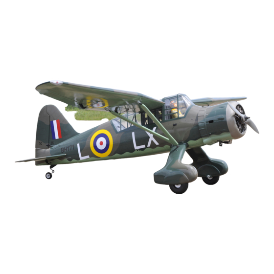
Westland Lysander
Scale 1:6
ALL BALSA - PLY WOOD CONSTRUCTION.
COVERED IN A HEAT-SHRINK FILM WITH PRINTED.
95% ALMOST READY TO FLY
SPECIFICATION:
- Wingspan: 2,540mm (100in).
- Length: 1,600mm (63in).
- Weight: 6.8 - 7.1kg (14.96 - 15.62 lbs).
- Wing area: 68.6 dm .
- Wing loading: 99.13g/dm .
- Wing type: Naca Airfoil.
- Servo mount: 42mm x 21mm.
- Gear type:
Aluminium Hi-grade for main gear
(included).
- Tail gear type: CNC suspension metal struts
Instruction Manual Book
2
2
Item code: BH170
Gas and EP
Parts listing required (not included):
- Radio: 06 channels.
- Servo: 08 servos.
- Engine: 30 - 35 cc gas.
- Motor: Brushless outrunner 2500 - 3000W, 245KV.
- Propeller: Suit with your engine.
Recommended Motor
and Battery set up (not included):
Admiral GP26 6330-245kV
- Motor:
- Lipo cell: 8-10 cells 4,000-5,500mAh.
- Receiver battery: 6V/ 1200mAh.
- ESC: 80 - 120A.
(NGH 35cc recommended)
Made in Vietnam.
Advertisement
Table of Contents

Subscribe to Our Youtube Channel
Related Manuals for Black Horse Model WESTLAND LYSANDER


Summary of Contents for Black Horse Model WESTLAND LYSANDER
- Page 1 Instruction Manual Book Item code: BH170 Westland Lysander Scale 1:6 Gas and EP ALL BALSA - PLY WOOD CONSTRUCTION. COVERED IN A HEAT-SHRINK FILM WITH PRINTED. 95% ALMOST READY TO FLY SPECIFICATION: Parts listing required (not included): - Radio: 06 channels.
-
Page 2: Table Of Contents
Instruction manual WESTLAND LYSANDER Item code: BH170 TABLE OF CONTENTS Symbols used throughout this instruction Installing the fuel tank.........26 manual, comprise........2 Installing the throttle........27 Warranty............3 Mounting the cowl........28 Disclaimer............3 Installing the switch, receiver and battery...29 Note.............3 Installing the switch........29 Safety precaution.........3 Installing the electric motor (EP version)..30... -
Page 3: Warranty
The the use or misuse of Black Horse Model products. By the model will only be strong and fly well if you complete your... -
Page 4: Parts Listing (Not Included)
Instruction manual WESTLAND LYSANDER Item code: BH170 PARTS LISTING (NOT INCLUDED). Servo extension leads....2 pcs. 540mm ..2 pcs. 220mm ..4 pcs. 190mm ..2 pcs. Engine: 33 - 35 cc gas Motor: Admiral GP26 6330 ..1 pcs Propeller. - Page 5 Instruction manual WESTLAND LYSANDER Item code: BH170 : Fuselage. ood - motor mount : Wing panel (2a, 2b). luminium landing gear (13a, 13b) : Horizontal stabilizer (3a, 3b). Wheel pants (14a, 14b). : Vertical stabilizer : Wheels. : Aluminium wing dihedral brace.
-
Page 6: Wing Plastic Light
Instruction manual WESTLAND LYSANDER Item code: BH170 WING PLASTIC LIGHT INSTALLING THE AILERONS AND FLAPS. 69mm Pinned hinge 44mm Pinned hinge - - - - - - - - - - - - - 8 - - - - - - - - - - - - - 8... -
Page 7: Installing The Ailerons And Flaps Servos
Instruction manual WESTLAND LYSANDER Item code: BH170 Make certain the hinges are adequately secured with glue. If they come loose in flight accidents may result. Bottom view INSTINSTALLING THE AILERONS AND FLAPS SERVOS Place the servo into the servo tray. Center the servo within the tray and drill 1.5mm pilot holes... - Page 8 Instruction manual WESTLAND LYSANDER Item code: BH170 3mm Flat Washer Horn Ball link 3x15mm Tp Screw 2x10mm Tp Screw - - - - 4 - - - - - - - 6 - - - - 8 - - - - 2...
- Page 9 Instruction manual WESTLAND LYSANDER Item code: BH170 Aileron Aileron servos. 2 mm approx.16mm 3mm Flat Washer Aileron Aileron 3mm Hex Nut 3x12mm Cap Screw Aileron Aileron 1.5mm Screw 96mm 2x10mm Tp Screw Aileron 1.5mm Cut off shaded portion Drill holes using the stated.
- Page 10 Instruction manual WESTLAND LYSANDER Item code: BH170 2x10mm For Aileron Tp Screw For Flaps Bottom View Aileron Aileron Aileron 3x15mm Tp Screw Horn 3x12mm Cap Screw Aileron Aileron C . A Bottom View Flap Flap Flap 3x12mm 3x15mm Tp Screw...
-
Page 11: Installing The Fuselage Servos
Instruction manual WESTLAND LYSANDER Item code: BH170 INSTALLING THE FUSELAGE SERVOS 1) Install the rubber grommets and brass collets into the elevator, rudder and throttle servos. Test fit the servos into the servo tray. Trim the tray if necessary to fit your servos. -
Page 12: Installing The Main Gear
Instruction manual WESTLAND LYSANDER Item code: BH170 INSTALLING THE MAIN GEAR 115mm Wheels. 5x65mm Socket Head 4mm Spring Washer Cap Screw - - - - - - - 4 - - - - 2 4x20mm Cap Screw 5mm Hex Nut... - Page 13 Instruction manual WESTLAND LYSANDER Item code: BH170 Secure the gear to the fuselage. Fuselage Bottom side. 4mm Spring Washer 4mm Flat Washer 4x20mm Cap Screw 3x10mm 3x10mm 2.5mm Cut off shaded portion Drill holes using the stated. carefully. (in this case 2.5mm...
-
Page 14: Installing The Tail Gear
Instruction manual WESTLAND LYSANDER Item code: BH170 INSTALLING THE TAIL GEAR 5x25mm Socket Head 3mm Flat Washer 47mm Wheels Cap Screw - - - - - - - - - - 4 - - - - - - - - 1... - Page 15 Instruction manual WESTLAND LYSANDER Item code: BH170 Crimp Crimp Cable rod Bottom View 3mm Flat Washer 3mm Spring Washer 3x16mm Button Head Cap Screw...
- Page 16 Instruction manual WESTLAND LYSANDER Item code: BH170 Bottom View Bottom View Open / Close...
- Page 17 Instruction manual WESTLAND LYSANDER Item code: BH170 Servo tail gear Metal Clevis Cab link Hex Nut Fuselage top side Servo tail gear Cut off excess. Must be purchased Cut off shaded portion separately! carefully. Drill holes using the stated. (in this case 1.5mm 1.5mm...
-
Page 18: Installing Horizontal Stabilizer
Instruction manual WESTLAND LYSANDER Item code: BH170 INSTALLING HORIZONTAL STABILIZER 3x15mm Tp Screw 2.6x872mm Push rod 3x12mm Cap Screw - - - - - - - 4 - - - 2 - - - - - - 4 44mm Pinned hinge... - Page 19 Instruction manual WESTLAND LYSANDER Item code: BH170 Top Side Top side 3x15mm Bottom side Tp Screw Horn 3x12mm Cap Screw Elevator pushrod Horn Apply epoxy glue.
-
Page 20: Installing Vertical Stabilizer
Instruction manual WESTLAND LYSANDER Item code: BH170 Fuselage top side Elevator pushrod Elevator servo 3x12mm Screw Servo arm 3mm Flat washer Ball link Push rod 3mm Hex Nut INSTALLING VERTICAL STABILIZER 3x15mm Tp Screw 2.6x895mm Push rod 3x12mm Cap Screw... - Page 21 Instruction manual WESTLAND LYSANDER Item code: BH170 Rudder Top Side Cut off shaded portion Apply epoxy glue. carefully.
- Page 22 Instruction manual WESTLAND LYSANDER Item code: BH170 Control horn, linkages and for rudder are installed the same way as the elevator before (see page 19). Horn Rudder pushrod Rudder pushrod Rudder Rudder servo Fuselage top side Rudder servo Rudder servo...
-
Page 23: Installing The Engine
Instruction manual WESTLAND LYSANDER Item code: BH170 INSTALLING THE ENGINE May be you also need to trim some wood from the tri-angle Using plate of plywood (supplied with the kit) mark the holes wood for the installation is easy. onto the fire wall for installing the engine mount for DLE-35CC or OS-33CC. - Page 24 Instruction manual WESTLAND LYSANDER Item code: BH170 16x5mm Rubber Washer 12x60mm Aluminium 5mm Spring Washer - - - - - - - 4 - - - - - - - 4 - - - - - - - 4 5x90mm Socket Head...
-
Page 25: Installing The Stopper
Instruction manual WESTLAND LYSANDER Item code: BH170 INSTALLING THE STOPPER Cut off shaded portion... -
Page 26: Installing The Fuel Tank
Instruction manual WESTLAND LYSANDER Item code: BH170 5. When satisfied with the alignment of the stopper INSTALLING THE FUEL TANK assembly tighten the 3mm x 20mm machine screw until the rubber stopper expands and 1. Using a modeling knife, cut one length of silicon seals the tank opening. -
Page 27: Installing The Throttle
Instruction manual WESTLAND LYSANDER Item code: BH170 INSTALLING THE THROTTLE direction. When the throttle stick is moved forward from idle to full throttle, the throttle barrel should Connector - - - - - - - - - 1 also open and close using this motion. If not, reverse the direction of the servo, using the transmitter. -
Page 28: Mounting The Cowl
Instruction manual WESTLAND LYSANDER Item code: BH170 MOUNTING THE COWL 4) While holding the cowl firmly in position, drill 1) Remove the muf f ler and needle valve assembly four 1,6mm pilot holes through both the cowl and from the engine. Slide the fiberglass cowl over the the side edges of the firewall. -
Page 29: Installing The Switch, Receiver And Battery
Instruction manual WESTLAND LYSANDER Item code: BH170 3x12mm Tp Screw Top Side - - - - 4 3x12mm Screw INSTALLING THE SWITCH, RECEIVER AND BATTERY . INSTALLING THE SWITCH 1) Plug the servo leads and the switch lead into the receiver. You may want to plug an aileron... -
Page 30: Installing The Electric Motor (Ep Version)
Instruction manual WESTLAND LYSANDER Item code: BH170 INSTALLING THE ELECTRIC MOTOR (EP VERSION) M4 Blind Nut 10x20mm Aluminium 4x40mm Socket Head Cap Screw - - - - - 4 - - 4 M4 Blind Nut 4mm Flat Washer - - - - - 4... - Page 31 Instruction manual WESTLAND LYSANDER Item code: BH170 Fuselage top side 5mm Rubber Washer 5mm Flat Washer 5mm Spring Washer When rotating clock wise, change the 12x60mm connection of 2 wires. 5mm Flat Washer 5x90mm Fuselage top side 160mm Apply threadlocker (screw cement).
-
Page 32: Installing Cockpit Fuselage
Instruction manual WESTLAND LYSANDER Item code: BH170 INSTALLING COCKPIT FUSELAGE Position the canopy so the rear frame on the canopy is aligned with the rear edge of the cockpit opening. Use canopy glue to secure the canopy to the canopy hatch. Use low-tack tape to hold the canopy in position until the glue fully cures. -
Page 33: Installing Balsa Plywood Wing Struts
Instruction manual WESTLAND LYSANDER Item code: BH170 Fuselage top side Adhesive tape. Canopy glue 2.5mm Adhesive tape. Adhesive tape. INSTALLING BALSA PLYWOOD WING STRUTS 3x12mm Cap Screw Aluminium Fuselage Hair Pin 3x6mm Button Head Strut Attachment - - - - - - - 2... - Page 34 Instruction manual WESTLAND LYSANDER Item code: BH170 3x6mm Button Head Cap Screw 2.5mm 3x 6mm Button Head Cap Screw 2.5mm 3x 6mm Button Head Cap Screw 2.5mm 3x 6mm Button Head Cap Screw Assemble left and right sides the same way.
- Page 35 Instruction manual WESTLAND LYSANDER Item code: BH170 3x12mm Tp scew 3x12mm Cap scew Bottom view Fuselage top side 4x6mm Screw Assemble left and right sides the same way.
-
Page 36: Iinstalling The Wing To The Fuselage
Instruction manual WESTLAND LYSANDER Item code: BH170 INSTALLING THE WING TO THE FUSELAGE 19x542mm Aluminium tube. *** Test fit the aluminium tube dihedral brace - - - - 1 into each wing haft. The brace should slide in easily. If not, use 220 grit sand around the edges and ends of the brace until it fits properly. - Page 37 Instruction manual WESTLAND LYSANDER Item code: BH170 Cap screw for main wing fixture. Fuselage top side...
-
Page 38: Installing The Propeller
Instruction manual WESTLAND LYSANDER Item code: BH170 INSTALLING THE PROPELLER Fuselage top side Must be purchased separately! -
Page 39: Balancing
Instruction manual WESTLAND LYSANDER Item code: BH170 BALANCING 2) If one side of the wing fall, that side is heavier than the opposite. Add small amounts of lead weight to the bottom side of the lighter wing half's 1) It is critical that your airplane be balanced wing tip. -
Page 40: For Your Radio Installation Basic Connection For Airplane And Adjustment Of Servos
Instruction manual WESTLAND LYSANDER Item code: BH170 FOR YOUR RADIO INSTALLATION BASIC CONNECTION FOR AIRPLANE AND ADJUSTMENT OF SERVOS Example of connection For more information, refer to radio system instruction manual. Follow instruction manual of Engine and Battery. Aileron Servo... -
Page 41: Main Gear Dimensional Detail
MAIN GEAR DIMENSIONAL DETAIL 23mm 35mm 66.5mm 5.1mm hold 41mm 210mm TAIL GEAR DIMENSIONAL DETAIL 47mm 155mm... - Page 43 I/C FLYING WARNINGS Always operate in open areas, away from NEVER fly near power lines,aerials or ALWAYS adjust the engine from behind factories, hospitals, schools, buildings other dangerous areas including airports, the propeller, and do not allow any part of and houses etc.
- Page 44 I/C FLYING GUIDELINES Operate the control sticks on the ALWAYS land the model INTO When ready to fly, first extend transmitter and check that the the wind, this ensures that the the transmitter aerial. control surfaces move freely and in model lands at the slowest possible the CORRECT directions.
Need help?
Do you have a question about the WESTLAND LYSANDER and is the answer not in the manual?
Questions and answers