Table of Contents
Advertisement
Quick Links
Advertisement
Table of Contents

Related Manuals for Jeanneau MERRY FISHER 755


Summary of Contents for Jeanneau MERRY FISHER 755
- Page 1 MERRY FISHER 755 OWNER'S MANUAL 982813 Index E...
-
Page 3: Welcome Aboard
The whole JEANNEAU team welcomes you aboard. A JEANNEAU is made to last, in order to bring you all the pleasure you expect from a vessel over a period of many years. Each boat is subject to the utmost attention to detail from the design stage right through to launching. - Page 5 This user guide/owner's manual is not a maintenance or repair guide. In case of difficulty do not hesitate to call on the services of your concessionaire JEANNEAU. Any alterations which may affect the safety specifications of the boat must be assessed, carried out and recorded by persons qualified to do so.
- Page 6 Anyone on the deck shall wear a life jacket or a buoyancy aid. The safety regulations as defined by the sailing code and enforced by the ’’COLREG’’ should be observed. NAME PLATE: Some of the data is shown on the manufacturer's plate fixed to the boat. The explanation of the data is given in the appropriate chapters of this manual.
-
Page 7: Update
HISTORY OF UPDATES •Index A ........................11/2013 •Index B ........................05/2014 •Index C ........................09/2014 •Index D ........................10/2014 •Index E ........................01/2015 3/106... -
Page 9: Table Of Contents
CONTENTS MERRY FISHER 755 Anglais Code: 982813 Total number of pages: 106 Update 01/2015 Index E INTRODUCTION Chapter 1 ..SPECIFICATIONS AND WARRANTY..........Page 7 Chapter 2 ..SAFETY ..................Page 13 Chapter 3 ..HULL .....................Page 29 Chapter 4 ..DECK ....................Page 33... - Page 11 SPECIFICATIONS AND WARRANTY TECHNICAL SPECIFICATIONS CERTIFICATION DESIGN CATEGORY YOUR BOAT 7/106...
- Page 12 Battery capacity ....................1 x 110 Ah Cabins..........................1 Sleeping capacity....................... 4 Note: The capacities indicated are maximum (including options). Architect.................Bureau d'Etudes JEANNEAU CERTIFICATION CE Category Persons Maximum The engine is the main propulsion means of the MERRY FISHER 755. 8/106...
-
Page 13: Design Category
DESIGN CATEGORY Significant height of waves Wind force Design category to be considered (Beaufort scale) (in metres H 1/3) Vessel designed for navigation: A - "At high sea" Over 8 Over 4 m B - "In open sea" Up to and including 8 Up to and including 4 m C - "Near to the coast"... - Page 14 Category A: At high sea The boat is designed to sail in winds that may exceed Beaufort force 8 and in waves of a significant height of 4 metres and more. This craft is largely self-sufficient. Abnormal conditions such as hurricanes are excluded. Such conditions may be encountered on extended voyages, for example across oceans, or inshore when unsheltered from the wind and waves for several hundred nautical miles.
- Page 15 ............. ENGINE KEY NUMBER ............. Your agent JEANNEAU (Establishment of the company SPBI) BP 529 - 85505 LES HERBIERS cedex - FRANCE Tel. (33) 02 51 64 20 20 - Fax (33) 02 51 67 37 65 Internet : http://www.jeanneau.com(fr).
-
Page 17: Chapter 2 ...... Safety
SAFETY SAFETY EQUIPMENT GENERAL INFORMATION GAS SYSTEM RECOMMENDATIONS FOR GAS FIGHT AGAINST FIRE BILGE PUMP SYSTEM INSTRUCTIONS IN THE EVENT OF STEERING GEAR FAILURE 13/106... -
Page 18: Safety Equipment
SAFETY EQUIPMENT Swimming ladder (means of coming back onboard) Reference 1 Position of the liferaft (not supplied) Reference 2 SWIMMING LADDER (Reference 1) Closed Open LIFERAFT (Reference 2) 14/106... -
Page 19: General Information
GENERAL INFORMATION DANGERS The major hazards concern: - The gas system. - The electrical system. - The handling of the vessel. - The motorisation. Please refer to the relevant paragraphs. DANGER - Fuel leaks or vapour represent a danger of fire and explosion. - Leave the engine compartment ventilated for a long time before starting the engine. -
Page 20: Gas System
GAS SYSTEM Compartment Gas cylinder Locker closed Locker open Supply valve WARNING - For all recommendations concerning gas: Refer to chapter 2, «Safety». - Don't use a solution containing ammonia. - Don't use a flame to detect leaks. - Don't smoke, don't use a naked flame when you change the gas cylinder. 16/106... - Page 21 GAS SYSTEM DIAGRAM Designation Hot plate Valve Hot plate Gas cylinder locker Gas system Regulator valve Gas cylinder 17/106...
- Page 22 DIAGRAM - LOCATION - GAS SYSTEM Designation Cooker Supply valve - Gas Connector Regulator valve Gas cylinder locker Drain 18/106...
- Page 23 RECOMMENDATIONS FOR GAS Type of cylinder: butane, service pressure 10 kg/cm or according to current standards of your country). Close the valves on the system and on the cylinder when the appliances are not used. Close the valves before you change cylinders and immediately in case of emergency. Never leave unattended an appliance that is working.
- Page 24 EMERGENCY EVACUATION AND LOCATION OF EXTINGUISHERS Emergency exits in case of fire: - Sliding hatch - Passageway Recommended positioning of portable extinguishers (not supplied): - Galley 20/106...
- Page 25 FIGHT AGAINST FIRE It is the owner's or the skipper's responsibility: - To have the extinguishers checked in pursuance of the instructions given. - Use extinguisher replacements with equivalent features (same capacity and fire resistance) if the ones in place are out of date or have been used. - To tell the crew: - where the extinguishers are and how they work, - The location of the discharge opening in the reservoir petrol compartment,...
- Page 26 EXTINGUISHERS The extinguishers are part of the compulsory equipment. An extinguisher or a fire blanket shall be set less than 2 m from any flame appliance. Extinguishers must be placed less than 5 m from any berth. An extinguisher shall be less than 1 m from the steering station. The extinguishers must be in position (see "Extinguisher positions"...
- Page 27 FUEL SUPPLY VALVE - LOCATION Location - On the fuel tank HOW TO APPLY IN CASE OF FIRE COMPARTMENT FUEL TANK: - Stop the engine. - Inject the extinguishing product through the aperture. - Wait. 23/106...
-
Page 28: Chapter 3 ...... Hull
MANUAL BILGE PUMP Location Operation Arm - Pump 0,7/blow WARNING - The bilge pump system is not designed to provide buoyancy to the boat in case of damage. - The bilge pump system is designed to drive out the water being either sea spray or leaks but absolutely not the water coming through a hole in the hull, this hole being the result of a damage. - Page 29 BILGE PUMP SYSTEM - LOCATION 25/106...
- Page 30 Designation Electric bilge pump draining Electric bilge pump - Compartment tank - Petrol Manual bilge pump Drainage - Aft quarterdeck Chain locker drain scuppers Washbasin - Head Washbasin draining Galley sink Drainage - Galley sink Drain - Gas cylinder locker Draining of manual bilge pump Drainage - Compartment tank Cockpit drain...
-
Page 31: Bilge Pump System
BILGE PUMP SYSTEM PROCEDURE TO BE FOLLOWED - Switch on the electric bilge pump. - If necessary activate the manual pump. - Identify the source of the leak by tasting the water and decide on the relevant action to be taken: •... - Page 32 INSTRUCTIONS IN THE EVENT OF STEERING GEAR FAILURE - Stop the engine. - Drop anchor to avoid drifting. - Find out if you can solve the problem yourself by looking at the engine manual. - Request help. 28/106...
- Page 33 HULL MAINTENANCE OF THE HULL LIFTING 29/106...
- Page 34 LIFTING 1300 WETTED AREA: 16 M² PRECAUTION - Consult the harbourmaster's office to find out the conditions of water use and the maintenance area for cleaning your vessel. - It is necessary to seek the advice of your concessionnaire with regard to gel-coat repairs.
- Page 35 MAINTENANCE OF THE HULL The materials and equipments of your boat have been selected because of their high quality and performance and ease of maintenance. However you shall carry out a minimum maintenance in order to protect your boat from outside attacks (salt, sun, electrolysis ...).
-
Page 37: Chapter 4 ...... Deck
DECK NAVIGATION - DECK LAYOUT MOORING LINES TOWING STABILITY PREVENTION OF MAN OVERBOARD MOORING MAINTENANCE OF THE DECK 33/106... - Page 38 NAVIGATION - DECK LAYOUT A. Mooring cleats aft - Jack-lines to be fixed to the mooring cleats B. Towing: - at the bow, to be towed - at the stern, to tow C. Swimming ladder (means of coming back onboard) Ring - Handling: Used to maneuver the boat on a trailer WARNING...
-
Page 39: Mooring Lines
MOORING LINES A sufficient number of mooring lines suitably sized and suitable for the environment shall be on board for mooring your boat. - Always manoeuvre your boat using the engine. - Make allowance for the current and wind when you handle your boat. - Protect your boat to the highest degree with suitably sized fenders. - Page 40 Opening / Closure Sliding hatch Window lock Access Cockpit - Access Cockpit - Open To be kept closed when sailing Rod holder 36/106...
- Page 41 STABILITY Breaking waves represent a serious danger for stability and for taking in water. Close the companionway doors and hatches in heavy seas. During sailing keep all the portholes, windows and doors closed. - The stability is reduced when you add weight in the upper parts. - Stability may be reduced when towing a boat or when heavy weights are lifted with the davits.
- Page 42 DECK ELECTRIC WINDLASS - BREAKER LOCATION Clinch 1. Bow fitting 2. Handle position 3. Stowage - Remote control 4. Windlass 12V 5. Chain locker Breaker 80A Operation relay Location: Compartment tank - Petrol Location: Head 38/106...
- Page 43 OPERATION When using the windlass the hatch must be open and the chain brake in position. Location of battery switch - Compartment tank - Petrol The windlass operates on the service batteries. Turn on the boat engine. Battery switches to be turned on: - Battery switch - Positive 39/106...
- Page 45 MOORING As a rule, set the anchor in at least 3 times the depth of water. ANCHORING WITHOUT WINDLASS - Have your boat pointed into the wind and without speed. - Pay out the chain while moving back slowly. - Once the anchor snags, make it fast by reversing slightly. - Secure the hawser or the chain to the cleat .
- Page 46 ANCHORING BY HAND WITH USE OF A MANUAL WINDLASS - Release the windlass brake using the handle located in the chain locker so as to allow the chain lifter to turn freely and to release the anchor from the stem fitting - Re-engage the brake and let the anchor hang until the mooring position is reached.
- Page 47 - Thoroughly and frequently wash off the pulleys and sheaves with clear water. - Clean and polish with "Rénovateur chrome et inox Jeanneau" (supplied in the maintenance case) the stainless steel parts that may have small rusty spots or minor...
-
Page 49: Steering System
STEERING SYSTEM STEERING GEAR 45/106... - Page 50 LOCATION - STEERING SYSTEM Designation Steering rack Steering wheel Engine control lever Steering cable (Hydraulic) Control cables Watertight bellows Piston Outboard 46/106...
-
Page 51: Steering Gear
STEERING GEAR STEERING AND TURNS - The steering only works when the engine is running. It is impossible to make a turn without using the accelerator. - To turn, reduce speed, turn the wheel and then accelerate sufficiently to make the turn. - It stops under the effect of water resistance when the accelerator is released. -
Page 53: Chapter 6 ...... Interior
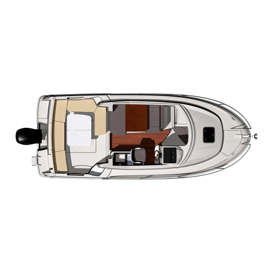
INTERIOR INTRODUCTION INTERIOR MAINTENANCE MAINTENANCE OF FABRICS 49/106... - Page 54 INTRODUCTION DECK SALOON INTERIOR ACCOMMODATION 50/106...
- Page 55 INTERIOR MAINTENANCE INTERIOR - Take advantage of the fine weather to take the settee and berth cushions out. - Put the cushions vertically if you leave the boat for long. - Use blinds to protect the inside of the boat against UV rays. - Carefully remove all crumbs.
- Page 57 Opening / Closure Sun roof 100% POLYESTER/DRALON JACQUARD If you cannot remove the fabric: - Clean with the vacuum cleaner. - Clean with a foam for synthetic fabrics (please refer to the product instructions). If you can remove the fabric: - Hand wash with an ordinary washing powder at 30°...
- Page 59 WATER AND SEWAGE WATER WATER TANKS WATER SYSTEM - DISTRIBUTION WATER SYSTEM - DRAINAGE SEWAGE 55/106...
-
Page 60: Chapter 11 .... Winter Storage
WATER TANK Water tank : 100 l Deck filler OPERATION In order to prevent any handling mistakes, never fill the water and fuel tanks at the same time. During filling, avoid handling contaminants near the fillers. Open and close the filler caps with the suitable key. Check the filler cap seals for condition during filling. - Page 61 WATER UNIT - 12V + FILTER Clean /Change the filter COCKPIT SHOWER SPRAY WARNING To avoid freezing during very cold spells and/or winter storage bleed the cockpit shower hose water system. PRECAUTION - Never operate the water system equipment when the valve is closed or the tank is empty (the electrical equipment may be damaged).
- Page 62 OPERATION Waste water from the sink, washbasins and heads is drained off by thru-hull fittings with ball valves (the valve is closed when the valve handle is perpendicular to the hose, the valve is open when the valve handle is in line with the hose). All the floors have holes (limber holes) for the water flow.
- Page 63 USE OF WASHBASIN Close the valves and turn off the taps after use. Sink (Galley) Washbasin (Head) Drainage Drainage ADVICE - RECOMMENDATION - Regularly check the valves and thru-hull seacocks for proper operation and watertightness. - Turn off the valves when the water system is not in use. - Visually check the water pump flow.
- Page 64 SEWAGE USE OF THE MARINE HEADS Before you use the heads, check that the water intake valve and draining valve are open. To empty the bowl: - Set the control lever of the pump slantwise (FLUSH). - Operate the pump. To dry the bowl: - Set the lever back vertical (DRY).
- Page 65 SEWAGE TANK Capacity: 80 litre WC evacuation - Deck Location: Head Filler cap 'WASTE' WARNING - The tanks' nominal capacity cannot be fully used due to the load and the need to maintain the correct trim. A 20% reserve should be kept. 61/106...
- Page 66 SCHEMATIC DIAGRAM - SEWAGE Designation Marine toilet Seawater inlet - WC WC evacuation - to sea WC evacuation - Deck - Filler cap "WASTE" Vent hole - Holding tank Holding tank - 80 litre 62/106...
- Page 67 RESPECT OF THE ENVIRONMENT - Remain informed of local regulations concerning the environment and follow the codes of best practice. - Do not drain the contents of the sewage tank near the coast or in zones where it is forbidden. - Make use of the port or marina pump facilities to drain the sewage tank before leaving port.
- Page 68 USE OF MARINE HEADS EQUIPPED WITH A WASTE HOLDING TANK (WHT) Open the water intake valve (valve handle parallel to the pipe). In the case of a direct discharge into the sea: Open the draining valve. In case you store the waste waters in the tank: Make sure the draining valve is closed (valve handle perpendicular to the pipe).
- Page 69 ELECTRICAL EQUIPMENT 12 V CIRCUIT - DC ELECTRICAL CIRCUIT, 110-220 V EQUIPMENT 65/106...
- Page 70 SCHEMATIC DIAGRAM - ELECTRICITY 66/106...
- Page 71 Designation Switch - Mooring light Switch - Compass Switch - Electric bilge pump - Forward cabin Switch - Electric bilge pump - Compartment tank Switch - Navigation lights Switch - Starboard windscreen wiper Switch - Port windscreen wiper Switch - Windscreen washer Switch - Water unit Compass Fuel gauge indicator...
- Page 72 ELECTRICAL CIRCUIT, 12 VDC GENERAL RECOMMENDATIONS - Never work on a live electric fitting. - The batteries must be strongly fastened. - Do not block the battery ventilation ducts, some of them may give off hydrogen which represents a danger of explosion. - The batteries must be handled with care.
- Page 73 ACCESS TO FUSES Hatch Head 20A 15A 5A 3A WARNING Always replace a fuse with one of the same size 69/106...
- Page 74 SWITCHES - WHEELHOUSE 1. Navigation light - Mooring light 5. Electric bilge pump 2. Lighting 6. Wiper 3. Water unit 7. Windscreen washer 4. Refrigeration unit Wiper tank: Location 70/106...
- Page 75 LOCATION BATTERY SWITCH Battery switch - Positive 71/106...
- Page 76 BATTERY SET Location - Cockpit locker Engine battery : 110A Service battery : 110A BATTERIES Battery charging is achieved through the alternator coupled to the engine or through use of the 220 V shore charger. Battery charger Power: 12V / 25A Keep the batteries charged enough (essential to ensure them a correct service life).
- Page 77 Always check the condition of the batteries and charge system before putting to sea WARNING - Never work on a live electric fitting - Do not touch the battery terminals, danger of electric shock. PRECAUTION - Switch off the electrical system with the battery switches when the boat is unattended. - Never leave the vessel unattended with the mains electricity switched on.
- Page 78 ELECTRICITY - LOCATION 74/106...
- Page 79 Designation Windlass - 12V Windlass remote control Windlass fuse Lighting - Forward cabin Motor - 12V - Wiper Lighting - WC Compass light Navigation light - Side - Starboard Navigation light - Side - Port side Electronics box Fuse box Switches Loud speakers Fridge - 12V...
- Page 80 ELECTRICAL CIRCUIT, 110-220 V GENERAL RECOMMENDATIONS Certain vessels are equipped (as either standard or optional features depending on the model)with a 110 V or 220 V circuit. The following measures are recommended in order to avoid the danger of electrical shock and fire: - Never work on a live electric fitting.
- Page 81 SHORE POWER SOCKET - 220V Shore power socket - 220V / 30A Breaker 220V / 32A Access - Under the sink Switch: General - Water heater - 220 V socket 77/106...
- Page 82 EQUIPMENT GENERAL INTRODUCTION (As far as possible) use electric appliances with double insulation or with three conductors (Neutral-Live wire-Ground). ELECTRONIC Wire runs are available to complete the boat equipment. Do not install electronic instruments or repeaters less than 1,50 m away from the radio loudspeakers.
- Page 83 LEAD LINES The loch and depth sounder transducers are located in the engine compartment. Keep the log sensor cowl close to the instrument so as to be able to intervene in complete safety. Do not store material on top of the sensors. AUTO PILOT - To supply power to all elements switch on the "Navigation"...
- Page 85 ENGINE GENERAL INFORMATION ENGINE FITTING 81/106...
- Page 86 GENERAL INFORMATION TYPE OF MOTORISATION Your vessel is fitted with a gasoline-powered outboard engine. Transmission type is: sail-drive. PRECAUTIONS OF USE, OPERATING ADVICE General point - In this vessel, do not install an engine with a greater power and weight than that recommended, this will create a danger for its stability.
- Page 87 DANGER - Stop the engine and refrain from smoking during fuel tank filling. - Make sure that the ventilation openings in the engine (and generator, if installed) compartment are well cleared. WARNING - The tanks' nominal capacity cannot be fully used due to the load and the need to maintain the correct trim PRECAUTION - Never run the engine when the boat is hauled out.
- Page 88 EPA version (United States Environmental Protection Agency) - The maintenance of the complete petrol circuit system must be done professionally every year. It is advisable to clean the circuit only with soapy water. All the fuel circuit connections must be checked once a year. - When cleaning the boat, be careful not to damage the valves, vent or fuel circuit filler.
- Page 89 LOCATION - SYSTEM - FUEL Designation Fuel gauge indicator Fuel supply valve 280 litres fuel tank Fuel filter Fuel filler Fuel gauge transmitter Vent hole 85/106...
- Page 90 Motor These instructions give detailed explanations on proper operation of the engine. - Refill before the fuel tanks have almost run dry (the fuel system may be stopped for lack of fuel). - Make sure you have enough fuel before sailing. Engine water intake valve The engine water valve is essential for the engine operation.
- Page 91 Fuel filter Engine running problems may have different origins, including dirty fuel. The injection pump may wear out if there is water in the system. The water results either from the condensation resulting from an insufficiently filled tank, or from a filler cap either not closed properly or with a damaged seal. In order to prevent any water infiltration, the fuel runs through two filters: - One filter is an integral part of the engine, its role is to filter fuel very finely.
- Page 92 WHEELHOUSE - DETAIL Synoptic 1. Compass 2. Tachometer 3. Starting motor 4. 12 V socket 5. Electrical controls 6. Lever - Motor 7. Steering wheel 8. Electrical controls 9. Electronic 10. Hifi 11. Gauge - Tank - Petrol 88/106...
- Page 93 Cutout DANGER Attach the cutout to the pilot at engine start. The instrument panel has all the testing functions of the engine and it does not require any special precaution (refer to engine leaflet). Check the clutch and accelerator cables (lubricate the end fittings and forks). 89/106...
- Page 94 VISIBILITY FROM THE STEERING STATION The international regulations to prevent collision at sea (COLREG) and the course regulations make mandatory a permanent and proper surveillance and the respect of priority. Make sure there is no other boat on your way. The visibility from the steering station may be obstructed in the following conditions: - Speed.
- Page 95 NAVIGATION: REMINDER OF SOME ADVICE Stability During sailing keep all the portholes, windows and doors closed. - The stability is reduced when you add weight in the upper parts. - Stability may be reduced when towing a boat or when heavy weights are lifted with the davits.
- Page 97 LAUNCHING LAUNCHING RECOMMENDATIONS 93/106...
- Page 98 POSITION OF HOISTING CRADLE AND STRAPS 1000 3400 Note: Measurements are expressed in mm. 94/106...
-
Page 99: Launching Recommendations
LAUNCHING RECOMMENDATIONS A lot of skill and care is required to commission your JEANNEAU boat. The proper working of all your boat's equipment is the result of the quality of the commissioning operations. In order to remain completely under guarantee in the case of any failure of parts or materials the first launching and the first trials of different equipment must be carried out by your JEANNEAU dealer. -
Page 101: Winter Storage
WINTER STORAGE LAYING UP PROTECTION AND MAINTENANCE 97/106... - Page 102 LAYING UP - Take ashore all the ship's log, the ropes that are not used for mooring, the galley equipment, supplies, clothes, the safety equipment, batteries, the gas cylinder. - Mark again the safety equipment, check the expiration dates, have the liferaft overhauled.
- Page 103 MOTOR The engine winterization shall be carried out by a professional. Depending on the boat location, afloat or ashore, winterization is different. Here are a few major tasks to carry out: Afloat - Drain the cooling system and fill it with antifreeze. - Shut off the battery switches, grease the terminals and check the battery voltage.
- Page 105 APPENDIXES CERTIFICATES OF STANDARDS 101/106...
- Page 106 Certificates of standards EPA 102/106...
- Page 107 103/106...
- Page 108 104/106...
- Page 109 105/106...
- Page 110 106/106...
Need help?
Do you have a question about the MERRY FISHER 755 and is the answer not in the manual?
Questions and answers