Table of Contents
Advertisement
Available languages
Available languages
Quick Links
FROG-A 24U
VEHICULAR SWING GATE OPERATOR
IN STA L LATI O N MA N U A L
Your model may look different than the model illustrated in this manual.
THIS PRODUCT IS TO BE INSTALLED AND
SERVICED BY A TRAINED GATE SYSTEMS
TECHNICIAN ONLY.
Visit www.liftmaster.com to locate a
professional installing dealer in your
area.
This model is for use on vehicular passage gates
ONLY and not intended for use on pedestrian
passage gates.
This model is intended for use in Class I
vehicular swing gate applications.
Advertisement
Chapters
Table of Contents

Related Manuals for CAME Frog-A 24U


Summary of Contents for CAME Frog-A 24U
- Page 1 FROG-A 24U VEHICULAR SWING GATE OPERATOR IN STA L LATI O N MA N U A L Your model may look different than the model illustrated in this manual. THIS PRODUCT IS TO BE INSTALLED AND This model is for use on vehicular passage gates...
-
Page 2: Table Of Contents
TABLE OF CONTENTS SAFETY PROGRAMMING SAFETY SYMBOL AND SIGNAL WORD REVIEW ......1 USING THE MENU . -
Page 3: Ul325 Model Classifications
SAFETY UL325 MODEL CLASSIFICATIONS UL325 MODEL CLASSIFICATIONS CLASS I – RESIDENTIAL VEHICULAR GATE OPERATOR A vehicular gate operator (or system) intended for use in a home of one-to four single family dwellings, or a garage or parking area associated therewith. UL325 ENTRAPMENT PROTECTION REQUIREMENTS This chart illustrates the entrapment protection requirements for the UL325 classes. -
Page 4: Safety Installation Information
SAFETY SAFETY INSTALLATION INFORMATION SAFETY INSTALLATION INFORMATION 1. Vehicular gate systems provide convenience and security. Gate systems are comprised of many component parts. The gate operator is only one component. Each gate system is specifically designed for an individual application. 2. -
Page 5: Gate Construction Information
SAFETY GATE CONSTRUCTION INFORMATION GATE CONSTRUCTION INFORMATION Vehicular gates should be installed in accordance with ASTM F2200: Standard Specification for Automated Vehicular Gate Construction. For a copy, contact ASTM directly at 610-832-9585 or www.astm.org. GENERAL REQUIREMENTS 3.1.3 A gap, measured in the horizontal plane parallel to the roadway, between a fixed stationary object nearest the roadway, (such as a gate support post) Gates shall be constructed in accordance with the provisions given for the and the gate frame when the gate is in either the fully open position or the... -
Page 6: Required Entrapment Protection Devices
SAFETY REQUIRED ENTRAPMENT PROTECTION DEVICES REQUIRED ENTRAPMENT PROTECTION DEVICES To prevent SERIOUS INJURY or DEATH from a moving gate: • Locate entrapment protection devices to protect between moving gate and RIGID objects, such as posts or walls. • Entrapment protection devices MUST be installed to protect anyone who may come near a moving gate. -
Page 7: Important Safety Information
SAFETY IMPORTANT SAFETY INFORMATION IMPORTANT SAFETY INFORMATION To prevent SERIOUS INJURY or DEATH: • Disconnect power at the fuse box BEFORE proceeding. Operator MUST be properly grounded and connected in accordance with national and local • READ AND FOLLOW ALL INSTRUCTIONS. electrical codes. -
Page 8: Introduction
Fuse Protection Line: 5 A Gear ratio: 1/1152 * The company CAME Cancelli Automatici is ISO 9001:2000 quality certified; it has Accessory Power: 24 Vac nominal Class II limited to 37W also obtained the ISO 14001 environmental safeguarding certification. CAME engineers and manufactures all of its products in Italy. -
Page 9: Operator And Control Panel Dimensions
INTRODUCTION OPERATOR AND CONTROL PANEL DIMENSIONS OPERATOR AND CONTROL PANEL DIMENSIONS OPERATOR 2.6" (6.60 cm) 2.3" (5.84 cm) 6.2" (15.74 cm) 16" 13" (40.63 cm) (33 cm) CONTROL PANEL 4.72" (11.98 cm) 8.46" (21.48 cm) 9.45" (24 cm) 5.71" (14.50 cm) -
Page 10: Preparation
PREPARATION TOOLS AND MATERIALS + WIRING CHART + SITE PREPARATION TOOLS AND MATERIALS Make sure you have all the tools and materials required for the installation. The installation should be completed in accordance with all national and local standards and regulations. The following tools may be needed for your installation: •... -
Page 11: Install The In-Ground Case
INSTALLATION INSTALL THE IN-GROUND CASE INSTALL THE IN-GROUND CASE Check the national and local building codes before installation. The instructions and illustrations in this manual are examples ONLY. Your installation may vary depending • To AVOID damaging gas, power or other underground utility lines, contact on space, obstructions, and accessories. -
Page 12: Fasten The Gearmotor And Assemble The Operator
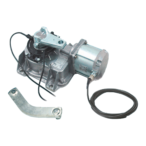
INSTALLATION FASTEN THE GEARMOTOR AND ASSEMBLE THE OPERATOR FASTEN THE GEARMOTOR AND ASSEMBLE Figure 1: Left Hand Installation THE OPERATOR Determine whether your installation is right or left-hand and follow the instructions (Gate in OPEN position) Gate Bracket accordingly. Remove the white plastic film on the bottom of the in-ground case. Gate Arm Bolt Fasten the gearmotor to the bolts on the bottom of the in-ground case using... -
Page 13: Mount The Control Panel
INSTALLATION MOUNT THE CONTROL PANEL MOUNT THE CONTROL PANEL Figure 1 The control panel MUST be mounted within 5 feet (1.52 m) of the gate operator. Attach the control panel to the mounting surface with cross slot Phillips head bolts in a protected area (Figure 1). Assemble the plastic hinges (Figure 2A). -
Page 14: Wiring
WIRING OVERVIEW OF CONTROL PANEL AND ELECTRONIC CARD OVERVIEW OF CONTROL PANEL AND ELECTRONIC CARD 1 Transformer To protect against fire and electrocution: 2 Card fuse (630mA-F 250VAC 5X20mm) • DISCONNECT power BEFORE installing or servicing operator. 3 Accessories fuse (2A-F 250VAC 5X20mm) 4 Electrolock fuse (3.15A-F 250VAC 5X20mm) 5 Display 6 Display -contrast adjustment... -
Page 15: Wire The Operator(S) To The Control Panel
WIRING WIRE THE OPERATOR(S) TO THE CONTROL PANEL Figure 1 WIRE THE OPERATOR(S) TO THE CONTROL Left-Hand Right-Hand PANEL Microswitch (Open Limit) Microswitch (Open Limit) Turn off the AC power from the main power source circuit breaker. Insert the cables through a watertight connector mounted in the back of the control panel. -
Page 16: Wire The Entrapment Protection Devices
WIRING WIRE THE ENTRAPMENT PROTECTION DEVICES WIRE THE ENTRAPMENT PROTECTION DEVICES DIR10 Photoelectric Sensors: An entrapment protection device such as photoelectric sensors or an edge MUST be wired to the operator and then configured for your application. Refer to page 18 - page 21 for programming information. - Page 17 WIRING WIRE THE ENTRAPMENT PROTECTION DEVICES WIRE THE ENTRAPMENT PROTECTION DEVICES Two-wire normally open edge Wireless Communicator EDGE SENSORS (CONTACT) An entrapment protection devices such as photoelectric sensors or an edge MUST be Receiver wired to the operator and then configured for your application using the Relay programming menu.
-
Page 18: Optional Wiring
OPTIONAL WIRING ACCESSORY POWER + COMMAND AND CONTROL DEVICES ACCESSORY POWER Command devices and accessories are 24V power. The overall power for accessories To protect against fire and electrocution: CANNOT exceed 37W. • DISCONNECT power BEFORE installing or servicing operator. Terminals 10 and 11 provide power for the following accessories: •... -
Page 19: Warning Devices
OPTIONAL WIRING WARNING DEVICES WARNING DEVICES Open-gate indicator light • Signals that gate is open; turns off when the gate is closed. Warning Device • Contact power: 24V A.C. - 25W maximum Flashing Light • Socket rating 24V-3W maximum NOTE: If the operator detects two sequential obstructions while running, the electronic card activates the warning device and blocks the signal from the remote control for 5 minutes. -
Page 20: Basic Setup For Typical Applications
PROGRAMMING BASIC SETUP FOR TYPICAL APPLICATIONS BASIC SETUP FOR TYPICAL APPLICATIONS Set the LANGUAGE: Press and hold the ENTER button for 1 second to see the menu on the display. Select LANGUAGE > (Choose the desired language). Set the basic function for the entrapment protection devices: Select FUNCTIONS then select the following menus to either determine the functionality or disable the entrapment protection devices: •... -
Page 21: Install And Program The
PROGRAMMING INSTALL AND PROGRAM THE SECURITY+ 2.0™ RADIO CARD INSTALL AND PROGRAM THE NOTICE: This device complies with Part 15 of the FCC rules and Industry Canada (IC) licence-exempt RSS-210. Operation is subject to the following two conditions: (1) this device may not cause harmful interference, and (2) this device must accept any interference received, SECURITY+ 2.0™... -
Page 22: Menu Descriptions
PROGRAMMING MENU DESCRIPTIONS MENU DESCRIPTIONS The menu is used to configure the operator based on your application and the devices that are connected to the operator. NOTE: The encoder menu only appears if "Config." is selected from the "Functions" menu. MAIN MENU SUB MENU DESCRIPTION... - Page 23 PROGRAMMING MENU DESCRIPTIONS MAIN MENU SUB MENU DESCRIPTION FUNCTIONS (continued...) The functions menu determines how your operator will function. Lamp E E Lamp: Setting up the flashing light or cycle lamp or courtesy lamp connected on 10-E: - Courtesy Light: Outdoor lamp that can be freely positioned, for additional lighting of the driveway - stays on for 5 minutes. - Cycle: Outdoor lamp, which can be positioned at leisure, for better illumination in the parking/driveway area.
- Page 24 PROGRAMMING MENU DESCRIPTIONS MAIN MENU SUB MENU DESCRIPTION USERS The USERS menu is used to program remote controls. Add User Add User: To create a new user and assigned function (max. 250 users). Mod. Name: To change a user number or existing name to another name. Mod.
-
Page 25: Adjustments
ADJUSTMENTS ADJUST THE BOLT IN THE MOTOR ARM + ADJUST THE LIMITS ADJUST THE BOLT IN THE MOTOR ARM Left-Hand Installation Electronically shut the gate against the closing end stop. Adjust the bolt until it touches the curved arm. Bolt When testing, adjust the screw to allow proper closing pressure of the gate and allow the gate to reconnect when manually released. -
Page 26: Manual Release
ADJUSTMENTS MANUAL RELEASE + TEST PHOTOELECTRIC SENSORS MANUAL RELEASE The manual release allows you to manually open or close the gate. The manual release allows the gate to hook back up when closing. Manual release operations need to be carried out during emergency procedures and with the power disconnected. -
Page 27: Maintenance
MAINTENANCE MAINTENANCE CHART MAINTENANCE CHART Disconnect all power to the operator before servicing. DESCRIPTION TASK CHECK AT LEAST ONCE EVERY MONTH 6 MONTHS 3 YEARS Entrapment Protection Devices Check and test for proper operation Warning Signs Make sure they are present Manual Disconnect Check and test for proper operation Gate... -
Page 28: Additional Services
MAINTENANCE MAINTENANCE LOG + ADDITIONAL SERVICES ADDITIONAL SERVICES Use the table below to log any additional services, repairs or modifications performed by a PROFESSIONAL TECHNICIAN: Installer’s stamp Operator name Date of job Technician’s signature Requester’s signature Job performed: _________________________________________________________________________________ ____________________________________________________________________________________________ ___________________________________________________________________________________________ ___________________ Installer’s stamp... -
Page 29: Troubleshooting
TROUBLESHOOTING TROUBLESHOOTING MALFUNCTION POTENTIAL CAUSE CHECK AND REMEDIES The gate will not open or close • There is no power • Check that the power is on • The operator is in manual release mode. • Reconnect operator • The remote control batteries are run down •... -
Page 30: Repair Parts
REPAIR PARTS Item Description Part Number Curved Lever 119RIA046 Motor Arm 119RIA045 Endstop Assembly Support 119RIA058 Endstop Assembly 119RIA057 Gear Motor Box 119RIA013 Motor 119RIA088 Slow Shaft 119RIA015 Worm Gear 119RIA016 Lower Flange 119RIA014 Limit Switch Assembly with Switch 119RIA059 NOT SHOWN- Control Panel- case only 119RTR375... -
Page 31: Warranty
This warranty gives you specific legal rights, and you may also have other rights, which vary from state to state (or jurisdiction to jurisdiction.) CAME’s responsibility for malfunctions and defects in equipment is limited to repair and replacement as set forth in this warranty statement. - Page 32 845 Larch Avenue Elmhurst, Illinois 60126-1196 01-36710C © 2012, The Chamberlain Group, Inc. – All Rights Reserved...
- Page 33 FROG-A 24U ACTIONNEUR DE BARRIÈRE VÉHICULAIRE À PIVOTEMENT MA N U E L D 'I N STA LLAT I O N Votre modèle peut sembler différent de celui illustré dans ce manuel. CE PRODUIT DOIT ÊTRE EXCLUSIVEMENT Ce modèle est pour utilisation sur les barrières de passage véhiculaire UNIQUEMENT et n'est...
- Page 34 TABLE DES MATIÈRES SÉCURITÉ PROGRAMMATION REVUE DES SYMBOLES DE SÉCURITÉ ET DES MOTS DE SIGNALEMENT ..1 UTILISATION DU MENU ......... . 18 CLASSIFICATIONS DU MODÈLE UL325 .
-
Page 35: Sécurité
SÉCURITÉ CLASSIFICATIONS DU MODÈLE UL325 CLASSIFICATIONS DU MODÈLE UL325 CLASSE 1 – ACTIONNEUR DE BARRIÈRE VÉHICULAIRE RÉSIDENTIEL Un actionneur (ou système) de barrière véhiculaire conçu pour utilisation dans une habitation de un à quatre logements individuels ou un garage ou une zone de stationnement associé... -
Page 36: Informations Sur L'installation Sécuritaire
SÉCURITÉ INFORMATIONS SUR L'INSTALLATION SÉCURITAIRE INFORMATIONS SUR L'INSTALLATION SÉCURITAIRE 1. Les systèmes de barrières véhiculaires fournissent commodité et sécurité. Les systèmes de barrières se composent de plusieurs pièces. L'actionneur de barrières n'est qu'une des composantes. Chaque système de barrière est conçu spécifiquement pour des applications individuelles. 2. -
Page 37: Renseignement Sur La Construction De La Barrière
SÉCURITÉ RENSEIGNEMENT SUR LA CONSTRUCTION DE LA BARRIÈRE RENSEIGNEMENT SUR LA CONSTRUCTION DE LA BARRIÈRE Les barrières véhiculaires devraient être installées conformément à ASTM F2200 : Spécification standard pour la construction de barrière véhiculaire automatisée. Pour en obtenir une copie, contacter directement ASTM au 610-832-9585 ou www.astm.org. EXIGENCES GÉNÉRALES 3.1.3 Un espace, mesuré... -
Page 38: Dispositifs De Protection Contre Le Piégeage Exigés
SÉCURITÉ DISPOSITIFS DE PROTECTION CONTRE LE PIÉGEAGE EXIGÉS DISPOSITIFS DE PROTECTION CONTRE LE PIÉGEAGE EXIGÉS AVERTISSEMENT Pour empêcher les BLESSURES GRAVES ou la MORT causées par une barrière en • Placer des dispositifs de protection contre le piégeage pour protéger pendant déplacement : les cycles d'ouverture ET de fermeture. -
Page 39: Renseignements De Sécurité Importants
SÉCURITÉ RENSEIGNEMENTS DE SÉCURITÉ IMPORTANTS RENSEIGNEMENTS DE SÉCURITÉ IMPORTANTS AVERTISSEMENT Pour éviter des BLESSURES GRAVES ou FATALES : • Déconnectez l'alimentation au niveau de la boîte à fusibles AVANT de poursuivre. L'actionneur DOIT ÊTRE correctement relié à la masse et connecté conformément •... -
Page 40: Introduction
Protection par fusible de la ligne CA : 5 A Ratio d'engrenage : 1/1152 * L'entreprise CAME Cancelli Automatici est certifiée ISO 9001:2000; elle a Alimentation accessoire : 24 Vca nominal Class II limité à 37W également obtenu la certification de protection environnementale ISO 14001 CAME conçoit et fabrique tous ses produits en Italie. -
Page 41: Dimensions De L'actionneur Et Du Panneau De Commande
INTRODUCTION DIMENSIONS DE L'ACTIONNEUR ET DU PANNEAU DE COMMANDE DIMENSIONS DE L'ACTIONNEUR ET DU PANNEAU DE COMMANDE ACTIONNEUR 2,6 pi (6,60 cm) 2,3 pi (5,84 cm) 6,2 pi (15,74 cm) 16 pi 13 pi (40,63 cm) (33 cm) PANNEAU DE COMMANDE 4,72 pi (11,98 cm) 8,46 pi (21,48 cm) -
Page 42: Préparation
PRÉPARATION OUTILS ET MATÉRIAUX + TABLEAU DE CÂBLAGE + PRÉPARATION DU SITE OUTILS ET MATÉRIAUX S'assurer d'avoir tous les outils et les matériaux nécessaires pour l'installation. L'installation devrait être effectuée conformément à toutes les normes et tous les règlements nationaux et locaux. Les outils suivants pourraient être nécessaires pour votre installation : •... -
Page 43: Installation Du Boîtier Enterré
INSTALLATION INSTALLATION DU BOÎTIER ENTERRÉ INSTALLATION DU BOÎTIER ENTERRÉ ATTENTION Vérifier les codes de construction nationaux et locaux avant l'installation. Les instructions et illustrations dans ce manuel sont des exemples SEULEMENT. Votre • Pour ÉVITER d'endommager les conduites souterraines de gaz, d'alimentation installation peut varier selon l'espace, les obstructions et les accessoires. -
Page 44: Fixation Du Moteur À Engrenage Et Assemblage De L'actionneur
INSTALLATION FIXATION DU MOTEUR À ENGRENAGE ET ASSEMBLAGE DE L'ACTIONNEUR FIXATION DU MOTEUR À ENGRENAGE ET Figure 1 : Installation à gauche ASSEMBLAGE DE L'ACTIONNEUR Déterminer si l'installation est à droite ou à gauche et suivre les instructions en (Barrière en position OUVERTE) Support de barrière conséquence. -
Page 45: Montage Du Panneau De Commande
INSTALLATION MONTAGE DU PANNEAU DE COMMANDE MONTAGE DU PANNEAU DE COMMANDE Figure 1 Le panneau de commande DOIT être monté à moins de 5 pieds (1,52 m) de l'actionneur de barrière. Fixer le panneau de commande à la surface de montage avec les boulons cruciformes Phillips dans une zone protégée (Figure 1). -
Page 46: Câblage
CÂBLAGE VUE D'ENSEMBLE DU PANNEAU DE COMMANDE ET DE LA CARTE ÉLECTRONIQUE VUE D'ENSEMBLE DU PANNEAU DE AVERTISSEMENT COMMANDE ET DE LA CARTE ÉLECTRONIQUE Pour protéger contre l'incendie ou l'électrocution : • DÉCONNECTER l'alimentation AVANT d'installer ou de faire l'entretien de 1 Transformateur l'actionneur. -
Page 47: Câblage De Ou Des Actionneurs Au Panneau De Commande
CÂBLAGE CÂBLAGE DE OU DES ACTIONNEURS AU PANNEAU DE COMMANDE Figure 1 CÂBLAGE DE OU DES ACTIONNEURS AU Gauche Droite PANNEAU DE COMMANDE Microinterrupteur (limite d'ouverture) Microinterrupteur (limite d'ouverture) Éteindre l'alimentation CA à partir du disjoncteur de l'alimentation principale. Insérer les câbles à travers un connecteur étanche monté à l'arrière du panneau de commande. -
Page 48: Câblage Des Dispositifs De Protection Contre Le Piégeage
CÂBLAGE CÂBLAGE DES DISPOSITIFS DE PROTECTION CONTRE LE PIÉGEAGE CÂBLAGE DES DISPOSITIFS DE PROTECTION CONTRE LE PIÉGEAGE Capteurs photoélectriques DIR10 : Un dispositif de protection contre le piégeage comme des capteurs photoélectriques ou une arête DOIVENT être câblés à l'actionneur puis configurés pour votre application. - Page 49 CÂBLAGE CÂBLAGE DES DISPOSITIFS DE PROTECTION CONTRE LE PIÉGEAGE CÂBLAGE DES DISPOSITIFS DE PROTECTION CONTRE LE PIÉGEAGE Arête normalement ouvert à 2 fils Communicateur sans fil CAPTEURS D'ARÊTE (CONTACT) Des dispositifs de protection contre le piégeage comme des capteurs photoélectriques Récepteur ALIM Relais...
-
Page 50: Câblage Optionnel
CÂBLAGE OPTIONNEL ALIMENTATION DES ACCESSOIRES + DISPOSITIFS DE COMMANDE ET DE CONTRÔLE ALIMENTATION ACCESSOIRE AVERTISSEMENT Les dispositifs de commande et accessoires sont sur une alimentation 24 V. La Pour protéger contre l'incendie ou l'électrocution : puissance globale pour les accessoires NE PEUT PAS excéder 37W. •... -
Page 51: Dispositifs D'avertissement
CÂBLAGE OPTIONNEL DISPOSITIFS D'AVERTISSEMENT DISPOSITIFS D'AVERTISSEMENT Témoin de barrière ouverte • Signale que la barrière est ouverte, s'éteint lorsque la barrière est fermée. Dispositif d'avertissement • Alimentation du contact : 24V C.A. - 25W maximum Lumière clignotante • Valeur nominale de la douille 24V-3W maximum REMARQUE : Si l’opérateur détecte deux obstructions consécutives quand il est en mouvement, la carte électronique active le module d’avertissement et bloque le signal des télécommandes pendant 5 minutes. -
Page 52: Configuration De Base Pour Applications Typiques
PROGRAMMATION CONFIGURATION DE BASE POUR APPLICATIONS TYPIQUES CONFIGURATION DE BASE POUR APPLICATIONS TYPIQUES Régler la LANGUE : Presser et tenir le bouton ENTER durant 1 seconde pour voir le menu sur l'affichage. Sélectionner LANGUE > (Choisir la langue désirée). Régler la fonction de base pour les dispositifs de protection contre le piégeage : Sélectionner FONCTIONS puis sélectionner les menus suivants pour déterminer la fonctionnalité... -
Page 53: Installer Et Programmer La Carte Radio Security+ 2.0
PROGRAMMATION INSTALLER ET PROGRAMMER LA CARTE RADIO SECURITY+ 2.0™ INSTALLER ET PROGRAMMER LA CARTE AVIS : Cet appareil est conforme aux dispositions de la partie 15 du règlement de la FCC et de l'exemption de licence IC (Industrie Canada) RSS-210. L’utilisation est sujette aux deux conditions ci-après : (1) ce dispositif ne peut causer des interférences nuisibles, et (2) ce RADIO SECURITY+ 2.0™... -
Page 54: Descriptions De Menus
PROGRAMMATION DESCRIPTIONS DE MENUS DESCRIPTIONS DE MENUS Le menu est utilisé pour configurer l'actionneur selon votre application et les dispositifs qui sont connectés à l'actionneur. REMARQUE : Le menu de l'encodeur apparait seulement si « Config » est sélectionné à partir du menu « Fonctions ». MENU PRINCIPAL SOUS-MENU DESCRIPTION LANGUE... - Page 55 PROGRAMMATION DESCRIPTIONS DE MENUS MENU SOUS-MENU DESCRIPTION PRINCIPAL FONCTIONS (suite...) Le menu fonctions détermine la façon dont votre actionneur fonctionnera. Lampe E Lampe E : Régler le clignotant ou la lampe de cycle ou la lampe d'accueil connectée sur 10-E : - Lampe d'accueil : Lampe extérieure qui peut être positionnée librement pour un éclairage supplémentaire de l'entrée - demeure allumée durant 5 minutes. - Cycle : Lampe extérieure qui peut être positionnée à...
- Page 56 PROGRAMMATION DESCRIPTIONS DE MENUS MENU SOUS-MENU DESCRIPTION PRINCIPAL UTILISATEURS Le menu UTILISATEURS est utilisé pour programmer les télécommandes. Ajouter utilisateur Ajouter utilisateur : Pour ajouter un nouvel utilisateur et des fonctions assignées (max. 250 utilisateurs) Mod. nom Mod. nom : Pour changer un numéro d'un utilisateur ou un nom existant à un autre nom Mod.
-
Page 57: Réglages
RÉGLAGES RÉGLAGE DU BOULON DANS LE BRAS DU MOTEUR + AJUSTEMENT DES LIMITES RÉGLAGE DU BOULON DANS LE BRAS DU Installation gauche MOTEUR Boulon Fermer la barrière électroniquement contre l'arrêt de fermeture. Ajuster le boulon jusqu'à ce qu'il touche le bras courbé. Bras courbé... -
Page 58: Dégagement Manuel
RÉGLAGES DÉGAGEMENT MANUEL + TEST DES CAPTEURS PHOTOÉLECTRIQUES DÉGAGEMENT MANUEL Le dégagement manuel vous permet d'ouvrir ou de fermer manuellement la barrière. Le dégagement manuel permet à la barrière de se raccrocher lors de la fermeture. Les opérations de dégagement manuel doivent être effectuées durant les procédures d'urgence et lorsque l'alimentation est déconnectée. -
Page 59: Entretien
ENTRETIEN TABLEAU D'ENTRETIEN TABLEAU D'ENTRETIEN Débrancher toute alimentation de l'actionneur avant de faire l'entretien. DESCRIPTION TÂCHE VÉRIFIER AU MOINS UNE FOIS CHAQUE MOIS 6 MOIS 3 ANS Dispositifs de protection contre le Vérifier et tester le bon fonctionnement piégeage Panneaux d'avertissement S'assurer qu'ils sont présents Débranchement manuel Vérifier et tester le bon fonctionnement... -
Page 60: Services Supplémentaires
ENTRETIEN JOURNAL D'ENTRETIEN + SERVICES SUPPLÉMENTAIRES SERVICES SUPPLÉMENTAIRES Utiliser le tableau ci-dessous pour noter tout services supplémentaires, réparations ou modifications effectuées par un TECHNICIEN PROFESSIONNEL : Timbre de l'installateur Nom de l'actionneur Date du travail Signature du technicien Signature du demandeur Travail effectué ... -
Page 61: Dépannage
DÉPANNAGE DÉPANNAGE DYSFONCTIONNEMENT CAUSE POSSIBLE VÉRIFICATION ET REMÈDES La barrière ne s'ouvre pas ou ne se • Il n'y a pas d'alimentation • Vérifier que l'alimentation est en fonction ferme pas • L'actionneur est en mode de dégagement manuel • Reconnecter l'actionneur •... -
Page 62: Pièces De Rechange
PIÈCES DE RECHANGE Article Description Numéro de pièce Levier courbé 119RIA046 Bras du moteur 119RIA045 Support d'assemblage de fin de course 119RIA058 Assemblage de fin de course 119RIA057 Boîte de moteur à engrenage 119RIA013 Moteur 119RIA088 Arbre lent 119RIA015 Vis sans fin 119RIA016 Bride du bas 119RIA014... -
Page 63: Garantie
être défectueuse et sera conditionnelle au fait que CAME ® ® recevra un avis d'un tel défaut durant la période de garantie. Les réclamations selon cette garantie ne peuvent être faites que par un acheteur des produits CAME ® « Client »). - Page 64 845 Larch Avenue Elmhurst, Illinois 60126-1196 01-36710C © 2012, The Chamberlain Group, Inc. – Tous droits réservés...
Need help?
Do you have a question about the Frog-A 24U and is the answer not in the manual?
Questions and answers