
Related Manuals for CAME BX-324


Summary of Contents for CAME BX-324
- Page 1 OPERATOR 119 B V1 0 I T FOR SLIDING GATES Installation manual BX-324 / BX-324V English...
- Page 2 • This product should only be used for the purpose for which it was explicitly OPERATIONS THEY ARE NOT EXPLICITLY REQUIRED AND ASKED to do in the designed. Any other use is considered dangerous. CAME Cancelli Automatici manuals. For repairs, adjustments and extraordinary maintenance, CONTACT S.p.A.
-
Page 3: Packing List
This symbol tells you what to say to the end users. ☞ REGULATORY REFERENCES Came Cancelli Automatici is a company with an ISO 9001-certified company quality management system and an ISO 14001-certified environmental management system. The product in question complies with the regulations referred to in the declaration of conformity. -
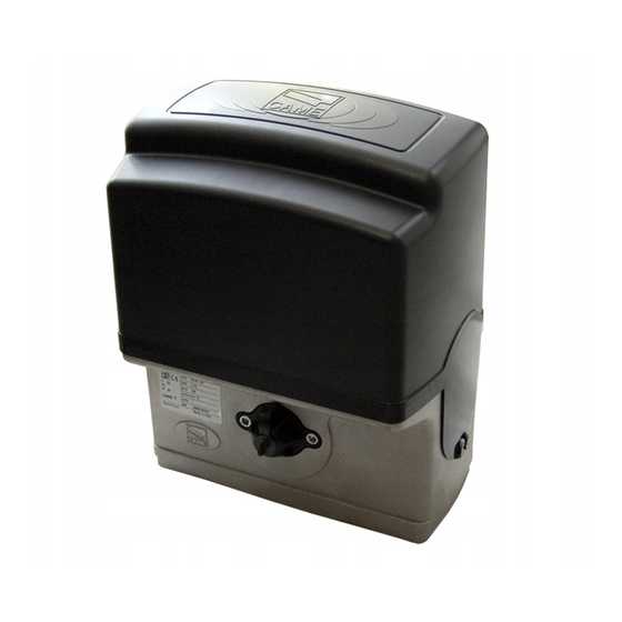
Page 4: Dimensions (Mm)
Description of the compo- nents 1. Cover 2. Control board mount 3. End run fins 4. Control board 5. Release key 6. Fixing plate 7. Fixing screws 8. Washer 9. Nut Dimensions (mm) GENERAL INSTALLATION INSTRUCTIONS Installation must be carried out by qualified and experienced personnel in compliance with applicable regulations. Preliminary checks Before installing the operator: •... -
Page 5: Tools And Materials
Tools and materials Make sure you have all the tools and materials you will need for the installation at hand to work in total safety and compliance with current standards and regulations. The figure shows some examples of installer’s tools. Types of cables and minimum thicknesses Cable length Cable length... -
Page 6: Installation
INSTALLATION The following illustrations are only examples, given that the space for securing the operator and accessories varies depending on the overall dimensions. The installation technician is responsible for choosing the most suitable solution. Installing corrugated tubes Make the hole for the counterframe. Prepare the junction boxes and corrugated tubes necessary for the connections from the inspection chamber. - Page 7 Fill the counterframe with cement. The plate must be perfectly level with the screw threads completely on the surface. Wait at least 24 hours for it to harden. Remove the counterframe and fill the hole around the block of cement with earth. Remove the nuts and washers from the screws.
- Page 8 Lift the gearmotor 5 to 10 mm up from the plate, using the threaded steel feet for any subsequent adjustments between the pinion and the rack. Unlock the gearmotor. Rest the rack on top of the gearmotor pinion. Weld or secure the rack to the gate along its entire length. To assemble the rack modules, use a piece of scrap and place it under the join point, securing it using two terminals.
- Page 9 Open and close the gate manually and adjust the pinion/rack coupling distance using the threaded feet (vertical adjustment) and the slots (horizontal adjustment). This prevents the weight of the gate bearing upon the operator. Rack Rack Pinion Pinion Slot Feet Vertical adjustment Horizontal adjustment When adjustment is complete, secure the gearmotor to the plate using the washers and nuts.
-
Page 10: Electrical Connections
ELECTRICAL CONNECTIONS Caution! Before intervening on the control panel, disconnect mains power. FUSE TABLE Control board power supply: 230 V AC, with 50-60 Hz frequency Line fuses 1.6 A-F Control device power supply: 24 VAC. The total power of the accessories should not exceed 40 W. Panel fuse 315 mA-F The functions must be set using the dip switches and the adjustments using the trimmers. -
Page 11: Control Devices
Connecting the gearmotor and end run The motor is designed to be installed on the left, inside view. Orange White Brown White Green Orange Green Opening Closing microswitch 24 VDC motor microswitch with encoder If installing on the right, inside view, reverse the motor and end run terminals on the control panel. Orange White Brown... -
Page 12: Safety Devices
Safety devices Photocells Photocells C1 = Contact (N.C.) of reopening when closing. DELTA-S Input for safety devices such as photocells, sensitive edges and other devices compliant with the EN 12978 standard. While the operator is closing, the opening of the contact causes the reversal of the direction of movement until completely open. -
Page 13: Final Operations
Activating the radio control Connect the RG58 cable of the antenna ❶. For the AF43S / AF43SM , radiofrequency cards only, position the jumper as shown according to the series of transmitters used❷. DISCONNECT POWER AND REMOVE THE BATTERIES, IF PRESENT. Insert the AF card on the control board. N.B. -
Page 14: Maintenance
Releasing the gearmotor The operation must be carried out while the power is off . ❸ ❶ ❷ LOCKING RELEASING MAINTENANCE Before any maintenance, disconnect power to prevent any possible dangerous situations that can be caused by accidental movement of the operator. ☞... -
Page 15: Troubleshooting
CAME CANCELLI AUTOMATICI S.p.A. implements an UNI EN ISO 14001-certified and compliant Environmental Management System at its plants, to ensure ☞ environmental protection. Please continue our efforts to protect the environment, something that CAME considers to be one of the foundations in developing its business and market strategies, simply by observing brief recommendations as regards disposal: DISPOSAL OF PACKAGING Packaging components (cardboard, plastic,etc.) can be disposed of together with normal household waste without any difficulty, by simply separating the different...
Need help?
Do you have a question about the BX-324 and is the answer not in the manual?
Questions and answers