CAME FROG Series Installation Manual
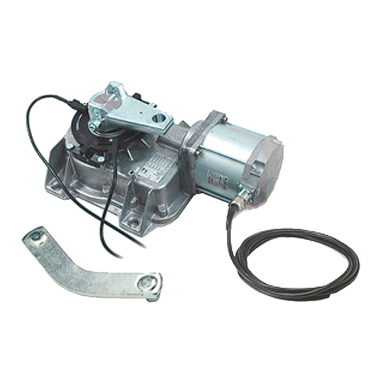
In-ground operator for swing gates
Hide thumbs
Also See for FROG Series:
- Installation manual (49 pages) ,
- Installation instructions manual (32 pages) ,
- Manual (16 pages)
Table of Contents
Advertisement
Quick Links
Advertisement
Table of Contents

Related Manuals for CAME FROG Series


Summary of Contents for CAME FROG Series
- Page 1 IN-GROUND OPERATOR FOR SWING GATES INSTALLATION MANUAL FROG-A 24U...
- Page 2 IMPORTANT UL-325 SAFETY INSTRUCTIONS FROG-A24U It is extremely important that all parties involved in the installation and operation of the gate operator system read and understand the following warning instructions. WARNING – To reduce the risk of injury or death: 1.
- Page 3 F. All openings of a horizontal slide gate are guarded or screened from the bottom of the gate to a minimum of 4 feet (1.22m) above the ground to prevent a 2-1/4 inch (57.2mm) diameter sphere from passing through the openings anywhere in the gate, and in that portion of the adjacent fence that the gate covers in the open position.
- Page 4 CAME® reserves the right to make the final determination as to whether there is a defect in the materials and/or workmanship, and whether or not a product is within the warranty period. CAME® is not responsible for any damages or other costs caused by, or which may result from installation, handling, non-recommended operation, product abuse, or modifications not authorized by CAME®...
-
Page 5: Power Connection
Some states do not allow the exclusion or limitation of incidental or consequential damages, so the above limitation or exclusion may not apply to you. CAME®‘s liability will be no more than the amount you paid for the product that is the subject of a claim. -
Page 6: Legend Of Symbols
For intensive use and condominiums: max weight of the gate 880lbs with max length of 11.5ft. 3 Reference Standards For its quality processes management CAME cancelli automatici is ISO 9001:2000 certified, and for its environmental management it is ISO 14001 certified. CAME engineers and manufactures all of its products in Italy. -
Page 7: Installation
4.3 Dimensions (inches) 5 Installation Installation must be carried out by expert qualified personnel and in full compliance with current regulations. 5.1 Preliminary checks Before installing, do the following: • Make sure you have a suitable omnipolar cut-off device with contacts more than 3 mm apart, and independent (sectioned off) power supply. -
Page 8: Standard Installation
5.3 Cable list and minimum thickness Connections Type of cable Length of cable 3 < 32ft Leng. cable 32 < 65ft Leng. cable 65 < 100ft Control panel power supply 230V 3G x 14AWG 3G x 14AWG 3G x 14AWG Motor power supply 24V 3 x 20AWG 3 x 20AWG... -
Page 9: Assembly Diagram
5.5 Assembly diagram Fig.2 2.64” in 2.6” in 5.6 Installing the unit - Check the efficiency of both moving and non-moving parts on the structure that will be supporting the operator. - Determine, depending on the type of supporting structure and desired opening, the exact position of the motor assembly by following the standard applications shown. -
Page 10: Manual Release
5.7 Manual release - In emergencies (i.e. power outages) the release mechanisms allow the gate to hook back up when closing. - You may choose among three different release models: model A4366 with customised key (Fig. 5-A), model A4365 with tri-lobed key and model A4364 with lever key (Fig. - Page 11 6.1 Adjusting the brake microswitches – Using the motor, make so that the gate leaf is max 20 inches from being fully opened. At this point do a first adjustment of the (endstop) microswitches, positioning them close to the magnet. Consider that this type of endstop reads the magnetic field.
-
Page 12: Safety Instructions
7 Safety instructions Important safety instructions This product must only be employed for its originally intended use. The automation using these gearmotors requires adequate safety systems on the gate leaves to detect any obstacles (e.g. sensitive edges), in compliance with UL 325 standards and CSA C22.2 No. -
Page 13: Periodic Maintenance
8 Maintenance 8.1 Periodic maintenance Periodic maintenance to be carried out by the end-user is as follows: wipe clean the glass surface of the photocells; check that the safety devices work properly; remove any obstructions. We suggest checking the state of lubrication and tightness of the anchoring screws on the operator. -
Page 14: Extraordinary Maintenance
Periodic maintenance log (for end-user) (every 6 months) Signature Date Notes 8.3 Extraordinary maintenance The following table serves to note down any extraordinary maintenance, repairs or improvements performed by specialised firms. Note: Any extraordinary maintenance must be performed by specialised technicians. Extraordinary maintenance log Installer’s stamp Operator name... -
Page 15: Demolition And Disposal
UNI EN ISO 14001 standard to ensure environmental protection. Please continue our efforts to protect the environment—which CAME considers one of the cardinal elements in the developmentof its operational and market strategies—simply by observing brief recommendations as regards disposal: DISPOSAL OF PACKAGING The packaging components (cardboard, plastic, etc.) are all classifiable as solid urban waste products and may be disposed of... - Page 16 CAME AMERICAS AUTOMATION, LLC 11345 NW 122nd STREET MEDLEY FL 33178 Tel 305.433.3307 Fax 305.396.3331...
Need help?
Do you have a question about the FROG Series and is the answer not in the manual?
Questions and answers