CAME BK Series Installation, Operation And Maintenance Manual
Sliding gate operator
Hide thumbs
Also See for BK Series:
- Installation manual (113 pages) ,
- Installation, operation and maintenance manual (18 pages) ,
- Manual (18 pages)
Table of Contents

Related Manuals for CAME BK Series


Summary of Contents for CAME BK Series
- Page 1 Automazione per cancelli scorrevoli FA00442M04 FA00442-IT Serie BK BK-800 / 1200 / 1800 / 2200 IT Italiano 1210 / 1810 / 2210 EN English FR Français MANUALE DI INSTALLAZIONE, USO E MANUTENZIONE RU Русский...
- Page 3 AVVERTENZE GENERALI PER L'UTILIZZATORE ⚠ ATTENZIONE! Importanti istruzioni di sicurezza. Attenersi strettamente alle presenti istruzioni per la sicurezza delle persone. Conservare queste istruzioni. •P • I ’ RIMA DI UTILIZZARE IL PRODOTTO LEGGERE TUTTE LE AVVERTENZE DI SICUREZZA L PRODOTTO DEVE ESSERE DESTINATO SOLO ALL USO PER IL QUALE È...
-
Page 4: Manutenzione
SBLOCCO MANUALE DEL MOTORIDUTTORE ⚠ L’attivazione dello sblocco manuale può provocare un movimento incontrollato del cancello a causa di anomalie mecca- niche o di uno sbilanciamento. SBLOCCO (fi gura - Inserire la chiave trilobata e girarla in senso orario. - Aprire lo sportello e ruotare la manopola di sblocco (fornita) in senso antiorario. BLOCCO (fi... -
Page 5: Avvertenze Generali Per L'installatore
AVVERTENZE GENERALI PER L'INSTALLATORE ⚠ ATTENZIONE! Importanti istruzioni di sicurezza. Seguire tutte le istruzioni in quanto un’installazione non corretta può portare a lesioni gravi. Prima di procedere leggere anche le avvertenze generali per l’utilizzatore. ’ L PRODOTTO DEVE ESSERE DESTINATO SOLO ALL USO PER IL QUALE È... - Page 6 LEGENDA Questo simbolo indica parti da leggere con attenzione. ⚠ Questo simbolo indica parti riguardanti la sicurezza. ☞ Questo simbolo indica cosa comunicare all’utente. Le misure, se non diversamente indicato, sono in millimetri. DESCRIZIONE Automazione completa di scheda elettronica e finecorsa meccanici per cancelli scorrevoli fino a 2.200 kg. DESTINAZIONE D’USO L’automazione è...
- Page 7 CICLI DI LAVORO Dato BK-800 / 1200 / 1210 / 1800 / 1810 / 2200 / 2210 Cicli/ora (n°) Cicli consecutivi (n°) Il calcolo dei cicli è riferito a un cancello di lunghezza standard di riferimento (vedere tipologia d’impiego), installato a regola d’arte, privo di confl itti meccanici e/o attriti accidentali, misurati a temperatura ambiente di 20°...
-
Page 8: Descrizione Delle Parti
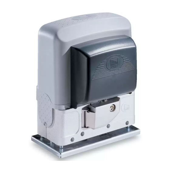
DESCRIZIONE DELLE PARTI 1. Coperchio 7. Alette di finecorsa 2. Motoriduttore 8. Finecorsa meccanico 3. Scheda elettronica 9. Ventola (serie BK-800) 4. Coperchio frontale 10. Trasformatore 5. Piastra di fissaggio 11. Sportello di sblocco 6. Porta-scheda elettronica 12. Chiave di sblocco IMPIANTO TIPO 1. -
Page 9: Verifiche Preliminari
INDICAZIONI GENERALI PER L'INSTALLAZIONE ⚠ L’installazione deve essere effettuata da personale qualificato ed esperto e nel pieno rispetto delle normative vigenti. VERIFICHE PRELIMINARI ⚠ Prima di procedere all’installazione dell’automazione è necessario: • controllare che i pattini-guida superiori non provochino attrito; •... - Page 10 POSA DELLA PIASTRA DI FISSAGGIO Preparare una cassa matta di dimensioni maggiori alla piastra di fissaggio e inserirla nello scavo. La cassa matta deve sporgere di 50 mm dal livello del suolo. Inserire una griglia di ferro all’interno della cassa matta per armare il cemento. Inserire le viti nella piastra di fissaggio e bloccarle con i dadi.
- Page 11 Togliere i dadi dalle viti. Inserire i cavi elettrici nei tubi fino a farli uscire di 600 mm circa. PREPARAZIONE DEL MOTORIDUTTORE Rimuovere il coperchio frontale e il coperchio del motoriduttore. Posizionare il motoriduttore sopra la piastra di fissaggio. Attenzione! I cavi elettrici devono passare sotto la cassa del motoriduttore e non devono entrare in contatto con parti che possono riscaldarsi durante l’uso (motore, trasformatore, ecc.).
- Page 12 FISSAGGIO DELLA CREMAGLIERA Se la cremagliera c’è già, procedere direttamente alla regolazione della distanza di accoppiamento pignone-cremagliera, altrimenti procedere con il fissaggio: - sbloccare il motoriduttore (vedi capitolo SBLOCCO MOTORIDUTTORE) ❶; - appoggiare la cremagliera sopra il pignone del motoriduttore ❷; - saldare o fissare la cremagliera al cancello in tutta la sua lunghezza ❸.
-
Page 13: Fissaggio Del Motoriduttore
FISSAGGIO DEL MOTORIDUTTORE Completata la regolazione, fissare il motoriduttore alla piastra con gli scontri e i dadi. DETERMINAZIONE DEI PUNTI DI FINECORSA In apertura: - aprire il cancello ; - infi lare l’aletta di fi necorsa di apertura sulla cremagliera fi no a far scattare il micro (molla) e fi ssarla con i grani . Molla ~ 20 mm In chiusura:... -
Page 14: Collegamenti Elettrici
COLLEGAMENTI ELETTRICI ⚠ Attenzione! Prima di intervenire sulla scheda elettronica, togliere la tensione di linea e, se presenti, scollegare le batterie. Le funzioni sui contatti di ingresso e uscita, le regolazioni dei tempi e la gestione degli utenti, vengono impostate e visualizzate sul display grafico. Tutte le connessioni sono protette da fusibili rapidi. - Page 15 COLLEGAMENTO DI FABBRICA U V W FC FA F Motoriduttore 230V (AC) Condensatore Microinterruttore di fi necorsa in chiusura Microinterruttore di fi necorsa in apertura ALIMENTAZIONE Per variare la coppia motore, spostare il faston indicato su una delle 120 / 230 V AC 50/60 Hz Rosso 4 posizioni;...
-
Page 16: Dispositivi Di Comando
DISPOSITIVI DI COMANDO Pulsante di STOP (contatto NC). Permette l’arresto del cancello con l’esclusione della chiusura automatica. Per riprendere il movimento premere il pulsante di comando o altro dispositivo di comando. Attivare la funzione F1 dalla programazione, se non viene utilizzato il pulsante, lasciare disattivata la funzione. -
Page 17: Dispositivi Di Sicurezza
DISPOSITIVI DI SICUREZZA Fotocellule Configurare il contatto CX o CY (NC), ingresso per dispositivi di sicurezza tipo fotocellule. Vedi funzioni F2 (ingresso CX) o F3 (ingresso CY) in: - C1 riapertura durante la chiusura. In fase di chiusura del cancello, l’apertura del contatto provoca l’inversione del movimento fino alla completa apertura;... - Page 18 ⚠ Nel caso di disturbi di radiofrequenza nell'impianto, il sistema wireless inibirà il normale funzionamento dell'automazione, appare sul display l'errore E17. RIO-CONN RIO-EDGE RIO-CELL RIO-LUX FUNZIONAMENTO ABBINATO O CRP (CAME REMOTE PROTOCOL) Collegamento seriale RS485 via CRP (Came Remote UTP CAT 5 Protocol) o per il funzionamento abbinato (vedi capitolo COLLEGAMENTO E FUNZIONAMENTO IN ABBINATO). A B GND ...
-
Page 19: Descrizione Dei Comandi
PROGRAMMAZIONE DESCRIZIONE DEI COMANDI Il tasto ESC serve per: - uscire dai menu; - annullare le modifiche; - fermare il cancello (solo per operazioni di collaudo). I tasti < > servono per: - spostarsi da una voce di menu a un’altra; - incrementare o decrementare un valore;... - Page 20 Uscita contatto (EX-W). È regolabile da 60 secondi a 180 secondi. F49 Gestione collegamento seriale OFF (default) / 1 = Abbinato / 3 = CRP Per abilitare il funzionamento abbinato o CRP (Came Remote Protocol). F50 Salvataggio dati OFF (default) / ON Salvataggio nella memory roll degli utenti e delle impostazioni memorizzate.
- Page 21 0 = 1200 Baud / 1 = 2400 Baud / 2 = 4800 Baud / 3 = 9600 Baud / 4 = 14400 Baud / 5 = 19200 Baud / 6 = 38400 Baud (default) / 7 = 57600 Baud / 8 = 115200 Baud Per l’impostazione della velocità di comunicazione utilizzata nel sistema di connessione CRP (Came Remote Protocol). F65 Ingresso wireless RIO-EDGE [T1]...
-
Page 22: Messa In Servizio
MESSA IN SERVIZIO Terminati i collegamenti elettrici, eseguire la messa in servizio dell’automazione da personale qualificato ed esperto. Prima di procedere, controllare che l’area di manovra sia libera da qualsiasi ostacolo e verificare la presenza di una battuta d’arresto meccanico in apertura e una in chiusura. - Page 23 SALVATAGGIO E CARICAMENTO DI DATI (UTENTI E CONFIGURAZIONE) CON LA MEMORY ROLL Procedura di memorizzazione dei dati relativi agli utenti e alla configurazione dell’impianto con la Memory roll, per poi riutilizzarli con un’altra scheda elettronica anche in un altro impianto. Attenzione! Le operazioni di inserimento ed estrazione della Memory roll, vanno eseguite in assenza di tensione.
-
Page 26: Operazioni Finali
MESSAGGI DI ERRORI I messaggi di errore sono indicati sul display. Errore test sicurezza. Tempo lavoro insufficiente. Sportello sblocco aperto. Ostacolo in chiusura. E 10 Ostacolo in apertura. E 11 Numero massimo di ostacoli rilevati. E 17 Errore sistema wireless. E 18 Manca configurazione sistema wireless. -
Page 27: Smaltimento Dell'imballo
UNI EN ISO 14001 a garanzia del rispetto e della tutela dell’ambiente. Vi chiediamo di continuare l’opera di tutela dell’ambiente, che CAME considera uno dei fondamenti di sviluppo delle proprie strategie operative e di mercato, semplicemente osservando brevi indicazioni in materia di smaltimento: SMALTIMENTO DELL’IMBALLO... - Page 28 I contenuti del manuale sono da ritenersi suscettibili di modifica in qualsiasi momento senza obbligo di preavviso. CAME S.p.A. Via Martiri Della Libertà, 15 31030 Dosson di Casier - Treviso - Italy tel. (+39) 0422 4940 - fax. (+39) 0422 4941...
- Page 29 Sliding gate operator FA00442-EN BK series BK-800 / 1200 / 1800 / 2200 1210 / 1810 / 2210 INSTALLATION OPERATION AND MAINTENANCE MANUAL EN English...
- Page 31 GENERAL PRECAUTIONS FOR USERS ⚠ WARNING! Important safety instructions. Carefully follow these instructions for the safety of people. Keep these instructions. • B • T EFORE USING THIS PRODUCT READ ALL ITS SAFETY PRECAUTIONS HIS PRODUCT SHOULD ONLY BE USED FOR THE PURPOSE FOR WHICH IT WAS EXPLICITLY S.P.A.
-
Page 32: Manually Releasing The Gearmotor
MANUALLY RELEASING THE GEARMOTOR ⚠ Manually releasing the gate may cause an uncontrolled movement of the gate due to possible mechanical anomalies or unbalancing. RELEASING (fi gure - Refi t the trilobe key and turn it clockwise. - Open the hatch and turn the supplied release handle counterclockwise. LOCKING (fi... - Page 33 GENERAL PRECAUTIONS FOR INSTALLERS ⚠ WARNING! Important safety instructions. Follow all of these instructions. Improper installation can cause serious bodily harm. Before continuing, also read the general precautions for users. S.P.A. HIS PRODUCT MUST ONLY BE USED FOR ITS SPECIFICALLY INTENDED PURPOSE NY OTHER USE IS DANGEROUS IS NOT LIABLE FOR ANY DAMAGE .
-
Page 34: Intended Use
This symbol shows which parts to read carefully. ⚠ This symbol shows which parts describe safety issues ☞ This symbol shows which parts to tell users about. The measurements, unless otherwise stated, are in millimeters. DESCRIPTION Operator complete with control board and mechanical end stops for sliding gates up to 2.200 kg in weight. INTENDED USE The operator is designed to power sliding gates used in apartment blocks and industrial plants. -
Page 35: Duty Cycles
DUTY CYCLES Datum BK-800 / 1200 / 1210 / 1800 / 1810 / 2200 / 2210 Cycles/hour (no.) Consecutive cycles (no.) The cycles calculation refers to a gate that has a standard reference length (see Intended Use), that is properly installed, without any mechanical and/or accidental confl... -
Page 36: Description Of Parts
DESCRIPTION OF PARTS 1. Cover 7. Limit-switch fins 2. Gearmotor 8. Mechanical limit switch 3. Control board 9. Fan (BK-800 series) 4. Front cover 10. Transformer 5. Anchoring plate 11. Release hatch 6. Control-board holder 12. Release key STANDARD INSTALLATION 1. -
Page 37: Installation
GENERAL INSTALLATION INDICATIONS ⚠ Only skilled, qualified staff must install this product. PRELIMINARY CHECKS ⚠ Before beginning the installation, do the following: • check that the upper slide-guides are friction-free; • make sure you have fitted opening and closing mechanical gate stops; •... - Page 38 FITTING THE ANCHORING PLATE Set up a foundation frame that is larger than the anchoring plate and sink it into the dug hole. The foundation frame must jut out by 50 mm above ground level. Fit an iron cage into the foundation frame to reinforce the concrete. Fit the bolts into the fastening plate and tighten them using the nuts.
- Page 39 Remove the nuts from the bolts. Fit the electric cables into the tubes so that they come out about 600 mm. PREPARING THE GEARMOTOR Remove the front cover and gearmotor cover. Place the gearmotor above the anchoring plate. Warning! The electrical cables must run under the gearmotor casing and must not touch any parts, such as the motor, transformer, and so on - that heat up during operation.
- Page 40 FASTENING THE RACK If the rack is already set up, the next step should be to adjust the rack-and-pinion coupling distance, otherwise, fasten it: - release the gearmotor (see chapter called RELEASING THE GEARMOTOR) ❶; - rest the rack onto the gearmotor pinion ❷; - either weld or fasten the rack along the entire length of the gate ❸.
-
Page 41: Establishing The Limit-Switch Points
FASTENING THE GEARMOTOR Once adjusting is complete, fasten the gearmotor to the plate using the plates and nuts. ESTABLISHING THE LIMIT-SWITCH POINTS For opening: - open the gate ; - fi t the opening limit-switch tab onto the rack until the micro switch activates (spring) and fasten it using the grub screws . Spring ~ 20 mm For closing:... -
Page 42: Electrical Connections
ELECTRICAL CONNECTIONS ⚠ Warning! Before doing any work on the control board, cut off the mains power supply, and disconnect any batteries. The functions on the input and output contacts, the time settings and user management, are set and viewed on the graphic display. All wiring connections are quick-fuse protected. -
Page 43: Power Supply
FACTORY WIRING U V W FC FA F 230V (AC) Gearmotor Condenser Closing limit-switch micro-switch Opening limit-switch micro-switch POWER SUPPLY To vary the motor torque, move the shown faston to one of the four 120 / 230 V AC 50/60 Hz positions;... -
Page 44: Control Devices
CONTROL DEVICES STOP button (NC contact). For stopping the gate while excluding automatic closing. To resume movement either press the control button or any other control device. Activate the F1 programming function. If the button is no used, leave this function deactivated. -
Page 45: Safety Devices
SAFETY DEVICES Photocells Configure contact CX or CY (NC), safety input for photocells. See F2 (CXinput) or F3 (CY input) set to: - C1 reopening during closing. When the gate is closing, opening the contact triggers the inversion of movement until the gate is fully open again; - C2 closing during opening. -
Page 46: Connections And Operation)
RIO-CONN RIO-EDGE RIO-CELL RIO-LUX PAIRED OPERATION OR CRP (CAME REMOTE PROTOCOL) Serial RS485 connection via CRP (Came Remote Protocol) UTP CAT 5 or for paired operation (see chapter called PAIRED CONNECTIONS AND OPERATION). A B GND Fit the RSE card. -
Page 47: Description Of The Commands
PROGRAMMING DESCRIPTION OF THE COMMANDS The ESC button is for: - exiting menus; - cancelling changes; - stopping the gate (only when testing). The < > keys are for: - moving from one item to another; - increasing or decreasing a value; - opening and closing the gate (only when testing). - Page 48 EX-W contact output. It is adjustable between 60 seconds and 180 seconds. F49 Managing serial connection OFF (default) / 1 = Paired / 3 = CRP To enable the paired operating mode or the CRP (Came Remote Protocol). F50 Save data OFF (default) / ON Saving users and saved settings in memory roll.
- Page 49 0 = 1200 Baud / 1 = 2400 Baud / 2 = 4800 Baud / 3 = 9600 Baud / 4 = 14400 Baud / 5 = 19200 Baud / 6 = 38400 Baud (default) / 7 = 57600 Baud / 8 = 115200 Baud For setting the communication speed used in the CRP (Came Remote Protocol) connection system. F65 Wireless input RIO-EDGE [T1] OFF (default) / P0 = P0 / P7 = P7 / P8 = P8 RIO-EDGE wireless safety device associated to a function of choice among those available: P0= stop gate and exclude any automatic closing;...
-
Page 50: Managing Users
COMMISSIONING Once the electrical connections are done, have only skilled, qualified staff commission the operator into service. Before continuing, make sure the area is free of any obstructions, and that there are mechanical, opening and closing gate stops in place. Power up and begin configuring the system. - Page 51 SAVING AND UPLOADING ALL DATA (USERS AND CONFIGURATION) WITH THE MEMORY ROLL Procedure for memorizing all of the system's user and configuration data by using the Memory Roll, so they can be used with another control board, even on another system. Warning! Fitting and extracting the Memory Roll must be done with the mains power disconnected.
-
Page 54: Error Messages
ERROR MESSAGES The error messages are shown on the display. Safety test error. Insufficient working time. Release hatch open. Closing obstruction. E 10 Opening obstruction. E 11 Maximum number of obstructions detected. E 17 Wireless system error. E 18 Missing wireless system configuration FINAL OPERATIONS Once the operator is up and running and the users are registered, refit the covers without pinching any wires. -
Page 55: Operation
SLAVE DISMANTLING AND DISPOSAL ☞ CAME S.p.A. applies a certified Environmental Management System at its premises, which is compliant with the UNI EN ISO 14001 standard to ensure the environment is safeguarded. Please continue safeguarding the environment. At CAME we consider it one of the fundamentals of our operating and market strategies. - Page 56 The contents of this manual may change, at any time, and without notice. CAME S.p.A. Via Martiri Della Libertà, 15 31030 Dosson di Casier - Treviso - Italy tel. (+39) 0422 4940 - fax. (+39) 0422 4941...
- Page 57 FA00442-FR Automatisme pour portails coulissants Série BK BK-800 / 1200 / 1800 / 2200 1210 / 1810 / 2210 FR Français MANUEL D'INSTALLATION, D'UTILISATION ET D'ENTRETIEN...
- Page 59 INSTRUCTIONS GÉNÉRALES POUR L'UTILISATEUR ⚠ ATTENTION ! Consignes de sécurité importantes. Respecter scrupuleusement les présentes instructions pour la sécurité des personnes. Conserver ces instructions. • L ’ • L IRE TOUTES LES CONSIGNES DE SÉCURITÉ AVANT D UTILISER LE PRODUIT E PRODUIT NE DEVRA ÊTRE DESTINÉ...
-
Page 60: Entretien
DÉBRAYAGE MANUEL DU MOTORÉDUCTEUR ⚠ L'activation du débrayage manuel peut provoquer un mouvement incontrôlé du portail à cause d’anomalies mécaniques ou d’un déséquilibrage. DÉBRAYAGE (fi gure ) - Introduire la clé triangulaire et la tourner dans le sens horaire. - Ouvrir le volet et tourner la poignée de débrayage (fournie) en sens anti-horaire. EMBRAYAGE (fi... - Page 61 INSTRUCTIONS GÉNÉRALES POUR L'INSTALLATEUR ⚠ ATTENTION ! Consignes de sécurité importantes. Suivre toutes les instructions étant donné qu'une installation incorrecte peut provoquer de graves lésions. Avant toute opération, lire également les instructions générales réservées à l’utilisateur. E PRODUIT NE DEVRA ÊTRE DESTINÉ QU À...
- Page 62 LÉGENDE Ce symbole indique des parties à lire attentivement. ⚠ Ce symbole indique des parties concernant la sécurité. ☞ Ce symbole indique ce qui doit être communiqué à l'utilisateur. Les dimensions sont exprimées en millimètres, sauf indication contraire. DESCRIPTION Automatisme avec carte électronique et fins de course mécaniques pour portails coulissants jusqu'à...
- Page 63 CYCLES DE FONCTIONNEMENT Donnée BK-800 / 1200 / 1210 / 1800 / 1810 / 2200 / 2210 Cycles/heure (n°) Cycles consécutifs (n°) Le calcul des cycles se réfère à un portail d’une longueur standard de référence (voir type d’utilisation), installé selon les règles de l’art, sans confl it mécanique ni aucun frottement accidentel.
-
Page 64: Description Des Parties
DESCRIPTION DES PARTIES 1. Couvercle 7. Ailettes de fin de course 2. Motoréducteur 8. Fin de course mécanique 3. Carte électronique 9. Ventilateur (série BK-800) 4. Couvercle frontal 10. Transformateur 5. Plaque de fixation 11. Volet de déblocage 6. Support carte électronique 12. -
Page 65: Contrôles Préliminaires
INSTRUCTIONS GÉNÉRALES POUR L'INSTALLATION ⚠ L’installation doit être effectuée par du personnel qualifié et dans le plein respect des normes en vigueur. CONTRÔLES PRÉLIMINAIRES ⚠ Avant d'installer l'automatisme, il faut : • contrôler que les patins de guidage supérieurs ne provoquent aucun frottement ; •... - Page 66 POSE DE LA PLAQUE DE FIXATION Préparer un coffrage plus grand que la plaque de fixation et l'introduire dans le trou. Le coffrage doit dépasser de 50 mm du sol. Insérer une grille en fer dans la tourelle pour armer le ciment. Introduire les vis dans la plaque de fixation et les bloquer à...
- Page 67 Enlever les écrous des vis. Introduire les câbles électriques dans les gaines jusqu'à ce qu'ils sortent d'environ 600 mm. PRÉPARATION DU MOTORÉDUCTEUR Enlever le couvercle frontal et le couvercle du motoréducteur. Positionner le motoréducteur sur la plaque de fixation. Attention ! Les câbles électriques doivent passer sous le carter du motoréducteur et ne doivent pas entrer en contact avec des parties pouvant devenir chaudes durant l’utilisation (moteur, transformateur, etc.).
-
Page 68: Fixation De La Crémaillère
FIXATION DE LA CRÉMAILLÈRE Si la crémaillère existe déjà, régler directement la distance d'accouplement pignon-crémaillère ou bien effectuer la fixation : - débrayer le motoréducteur (voir chapitre DÉBRAYAGE MOTORÉDUCTEUR) ❶ ; - poser la crémaillère sur le pignon du motoréducteur ❷ ; - souder ou fixer la crémaillère au portail sur toute sa longueur ❸. -
Page 69: Fixation Du Motoréducteur
FIXATION DU MOTORÉDUCTEUR Au terme du réglage, fixer le motoréducteur à la plaque à l'aide des butées et des écrous. DÉTERMINATION DES POINTS DE FIN DE COURSE En phase d'ouverture : - ouvrir le portail ; - enfi ler l'ailette de fi n de course d'ouverture sur la crémaillère jusqu'au déclic du micro-interrupteur (ressort) et la fi xer à l'aide des goujons . Ressort ~ 20 mm En phase de fermeture :... -
Page 70: Branchements Électriques
BRANCHEMENTS ÉLECTRIQUES ⚠ Attention ! Avant d'intervenir sur la carte électronique, mettre hors tension et déconnecter les éventuelles batteries. Les fonctions sur les contacts d'entrée et de sortie, les réglages des temps et la gestion des utilisateurs sont configurés et visualisés sur l'afficheur graphique. - Page 71 CONNEXION PAR DÉFAUT U V W FC FA F Motoréducteur 230V (AC) Condensateur Micro-interrupteur de fi n de course en phase de fermeture Micro-interrupteur de fi n de course en phase d'ouverture ALIMENTATION Pour varier le couple moteur, 120 / 230 VAC 50/60 Hz déplacer la cosse indiquée sur l'une Rouge des 4 positions : de 1 (min.) à...
-
Page 72: Dispositifs De Commande
DISPOSITIFS DE COMMANDE Bouton d'ARRÊT (contact NF). Permet l'arrêt du portail avec désactivation de la fermeture automatique. Pour reprendre le mouvement, appuyer sur le bouton de commande ou celui d'un autre dispositif de commande. Activer la fonction F1 depuis la programmation ; à défaut d’utilisation du bouton, laisser la fonction désactivée. -
Page 73: Dispositifs De Sécurité
DISPOSITIFS DE SÉCURITÉ Photocellules Configurer le contact CX ou CY (NF), entrée pour dispositifs de sécurité type photocellules. Voir fonctions F2 (entrée CX) ou F3 (entrée CY) dans : - C1 réouverture durant la fermeture. Durant la phase de fermeture du portail, l'ouverture du contact provoque l'inversion du mouvement jusqu'à ouverture totale du portail ;... - Page 74 RIO-CONN RIO-EDGE RIO-CELL RIO-LUX FONCTIONNEMENT VIS-À-VIS OU CRP (CAME REMOTE PROTOCOL) Connexion série RS485 via CRP (Came Remote Protocol) ou UTP CAT 5 pour le fonctionnement vis-à-vis (voir chapitre CONNEXION ET FONCTIONNEMENT EN MODE VIS-À-VIS). A B GND Insérer la carte RSE.
-
Page 75: Description Des Commandes
PROGRAMMATION DESCRIPTION DES COMMANDES La touche ESC permet de/d' : - sortir des menus - annuler les modifications - arrêter le portail (uniquement pour l’exécution d’essais). Les touches < > permettent de/d' : - se déplacer d'une option de menu à l'autre - augmenter ou diminuer une valeur - ouvrir et fermer le portail (uniquement pour l’exécution d’essais). - Page 76 Sortie contact (EX-W). Réglable de 60 secondes à 180 secondes. F49 Gestion connexion série OFF (par défaut) / 1 = Vis-à-vis / 3 = CRP Pour activer le fonctionnement vis-à-vis ou CRP (Came Remote Protocol). F50 Sauvegarde des données OFF (par défaut) / ON Sauvegarde dans la mémoire des utilisateurs et des confi...
- Page 77 19200 Bauds / 6 = 38400 Bauds (par défaut) / 7 = 57600 Bauds / 8 = 115200 Bauds Pour la confi guration de la vitesse de communication utilisée dans le système de connexion CRP (Came Remote Protocol). F65 Entrée sans fi l RIO-EDGE [T1] OFF (par défaut) / P0 = P0 / P7 = P7 / P8 = P8...
-
Page 78: Mise En Service
MISE EN SERVICE Au terme des branchements électriques, confier la mise en service de l’automatisme à du personnel qualifié. Avant toute opération, s'assurer que la zone de manœuvre ne présente aucun obstacle et s'assurer de la présence d'une butée d'arrêt mécanique aussi bien à... - Page 79 SAUVEGARDE ET TÉLÉCHARGEMENT DE DONNÉES (UTILISATEURS ET CONFIGURATION) AVEC LA MEMORY ROLL Procédure de mémorisation des données relatives aux utilisateurs et à la configuration de l'installation avec la Memory roll, de manière à ce qu'elles soient réutilisables sur une autre carte électronique, voire une autre installation. Attention ! Mettre hors tension avant d’exécuter les opérations d’installation et d’extraction de la Memory roll.
-
Page 82: Messages D'erreur
MESSAGES D'ERREUR Les messages d'erreur apparaissent à l'écran. Erreur test sécurité. Temps de fonctionnement insuffisant. Porte de déblocage ouverte. Obstacle à la fermeture. E 10 Obstacle à l'ouverture. E 11 Nombre maximum d'obstacles détectés. E 17 Erreur du système sans fil. E 18 Absence de configuration du système sans fil. -
Page 83: Élimination De L'emballage
SLAVE MISE AU REBUT ET ÉLIMINATION ☞ CAME S.p.A. adopte dans ses établissements un Système de Gestion Environnementale certifié et conforme à la norme UNI EN ISO 14001 qui garantit le respect et la sauvegarde de l'environnement. Nous vous demandons de poursuivre ces efforts de sauvegarde de l'environnement, que CAME considère comme l'un des fondements du développement de ses propres stratégies opérationnelles et de marché, en observant tout simplement de brèves indications en... - Page 84 Le contenu de ce manuel est susceptible de subir des modifications à tout moment et sans aucun préavis. CAME S.p.A. Via Martiri Della Libertà, 15 31030 Dosson di Casier - Treviso - Italy tel. (+39) 0422 4940 - fax. (+39) 0422 4941...
-
Page 85: Инструкция По Монтажу
Автоматика для откатных ворот FA00442-RU Серия BK BK-800 / 1200 / 1800 / 2200 1210 / 1810 / 2210 ИНСТРУКЦИЯ ПО МОНТАЖУ, ЭКСПЛУАТАЦИИ И ТЕХНИЧЕСКОМУ ОБСЛУЖИВАНИЮ RU Русский... - Page 87 • П • И ЕРЕД НАЧАЛОМ ЭКСПЛУАТАЦИИ ВНИМАТЕЛЬНО ПРОЧИТАЙТЕ ПРАВИЛА ТЕХНИКИ БЕЗОПАСНОСТИ ЗДЕЛИЕ ДОЛЖНО ИСПОЛЬЗОВАТЬСЯ ИСКЛЮЧИТЕЛЬНО ПО НАЗНАЧЕ . Л . CAME S. НИЮ ЮБОЕ ДРУГОЕ ПРИМЕНЕНИЕ РАССМАТРИВАЕТСЯ КАК ОПАСНОЕ НЕ НЕСЕТ НИКАКОЙ ОТВЕТСТВЕННОСТИ ЗА УЩЕРБ НАНЕСЕННЫЙ НЕПРАВИЛЬНЫМ • П...
-
Page 88: Техническое Обслуживание
РУЧНАЯ РАЗБЛОКИРОВКА ПРИВОДА ⚠ Активация ручной разблокировки может привести к неконтролируемому движению автоматики, вызванному ме- ханическими неисправностями или нарушением балансировки. РАЗБЛОКИРОВКА (рис. ) - Вставьте трехгранный ключ и поверните его по часовой стрелке. - Откройте дверцу и поверните ручку разблокировки (прилагается) против часовой стрелки. БЛОКИРОВКА... - Page 89 Строго следуйте всем инструкциям по безопасности, поскольку неправильный монтаж может привести к серьезным увечьям. Прежде чем продолжить, внимательно прочитайте общие предупреждения для пользователя. Э . Л . CAME ТО ИЗДЕЛИЕ ДОЛЖНО ИСПОЛЬЗОВАТЬСЯ ИСКЛЮЧИТЕЛЬНО ПО НАЗНАЧЕНИЮ ЮБОЕ ДРУГОЕ ПРИМЕНЕНИЕ РАССМАТРИВАЕТСЯ КАК ОПАСНОЕ . • НЕ НЕСЕТ НИКАКОЙ ОТВЕТСТВЕННОСТИ ЗА УЩЕРБ...
-
Page 90: Условные Обозначения
УСЛОВНЫЕ ОБОЗНАЧЕНИЯ Этот символ обозначает раздел, требующий особого внимания. ⚠ Этот символ обозначает раздел, связанный с вопросами безопасности. ☞ Этот символ обозначает раздел, предназначенный для ознакомления конечного пользователя. Все размеры приведены в мм, если не указано иное. ОПИСАНИЕ Автоматика, укомплектованная платой управления и механическими концевыми выключателями, для откатных ворот массой до 2200 кг. - Page 91 ЦИКЛЫ РАБОТЫ Данные BK-800 / 1200 / 1210 / 1800 / 1810 / 2200 / 2210 Кол-во циклов/час Кол-во последовательных циклов Расчет количества циклов выполнен для ворот стандартной длины (см. ограничения в использовании), установленных согласно правилам и нормам, не подверженных механическому воздействию и/или нежелательному трению, при температуре окружающей среды 20°C, согласно требованиям норматива...
-
Page 92: Основные Компоненты
ОСНОВНЫЕ КОМПОНЕНТЫ 1. Крышка 7. Упоры концевых выключателей 2. Мотор-редуктор 8. Механический концевой выключатель 3. Плата управления 9. Вентилятор (серия BK-800) 4. Передняя крышка 10. Трансформатор 5. Монтажное основание 11. Дверца разблокировки 6. Держатель платы 12. Устройство разблокировки ВАРИАНТ ТИПОВОЙ УСТАНОВКИ 1. - Page 93 ОБЩИЕ ИНСТРУКЦИИ ПО МОНТАЖУ ⚠ Монтаж должен производиться квалифицированным персоналом в полном соответствии с требованиями действующих норм безопасности. ПРЕДВАРИТЕЛЬНЫЕ ПРОВЕРКИ ⚠ Перед началом монтажных работ выполните следующее: • Проследите за тем, чтобы верхние направляющие скобы с роликами не вызывали трения. •...
- Page 94 УСТАНОВКА МОНТАЖНОГО ОСНОВАНИЯ Подготовьте опалубку большего, чем монтажное основание, размера и установите ее в яму. Опалубка должна подниматься над уровнем грунта на 50 мм. Вставьте железную сетку внутрь опалубки для армирования бетона. Вставьте винты в монтажное основание и зафиксируйте их с помощью гаек. При помощи отвертки и плоскогубцев отогните выбитые в...
- Page 95 Отвинтите гайки и снимите их с винтов. Вставьте электрические кабели в трубы таким образом, чтобы они выступали как минимум на 600 мм. ПОДГОТОВКА ПРИВОДА Снимите переднюю крышку и крышку привода. Установите привод на монтажное основание. Внимание! Электрические кабели должны проходить под корпусом привода и не должны соприкасаться с компонентами, нагревающимися...
- Page 96 КРЕПЛЕНИЕ ЗУБЧАТОЙ РЕЙКИ Если зубчатая рейка уже предусмотрена, необходимо перейти непосредственно к регулировке расстояния в паре «зубчатое колесо - зубчатая рейка». - разблокируйте мотор-редуктор (см. раздел «РАЗБЛОКИРОВКА МОТОР-РЕДУКТОРА») ❶; - установите зубчатую рейку на шестерню привода ❷; - приварите или прикрепите зубчатую рейку к воротам по всей длине ❸. При...
- Page 97 КРЕПЛЕНИЕ ПРИВОДА По окончании регулировки зафиксируйте привод на монтажном основании с помощью гаек. УСТАНОВКА КРАЙНИХ ПОЛОЖЕНИЙ При открывании: - откройте ворота ; - установите упор концевого выключателя открывания на зубчатую рейку так, чтобы он соприкасался с микровыключателем (пружиной), и зафиксируйте его винтами . Пружина...
-
Page 98: Электрические Подключения
ЭЛЕКТРИЧЕСКИЕ ПОДКЛЮЧЕНИЯ ⚠ Внимание! Перед началом работ по эксплуатации, ремонту, настройке и регулировке платы управления отключите сетевое электропитание и/или отсоедините аккумуляторы. Установка функций входных/выходных контактов, режимов работы и регулировок осуществляется с помощью графического дисплея. Все подключения защищены плавкими предохранителями. Плавкие предохранители ZBKN - ZBKEN 8 A (~230 В) - Входной... - Page 99 ЗАВОДСКИЕ ПОДКЛЮЧЕНИЯ U V W FC FA F Мотор-редуктор ~230 В Конденсатор Концевой микровыклю- чатель закрывания Концевой микровы- Н.З. ключатель открывания Н.З. ЭЛЕКТРОПИТАНИЕ Для изменения усилия ~120/230 В, 50/60 Гц привода установите указанную Красный клемму в одно из 4 положений: Серый...
- Page 100 УСТРОЙСТВА УПРАВЛЕНИЯ Кнопка «СТОП» (нормально-замкнутые контакты). Данная кнопка позво- ляет остановить движение ворот с последующим исключением цикла автоматического закрывания. Чтобы автоматика возобновила движение, необходимо нажать соответствующую кнопку управления или пульта ДУ. Активируйте функцию F1 в меню программирования; если кнопка не...
-
Page 101: Устройства Безопасности
УСТРОЙСТВА БЕЗОПАСНОСТИ Фотоэлементы Выберите режим работы для контактов CX или CY (нормально-замкнутых), предназначенных для подключения устройств безопасности , например, фотоэлементов. Смотрите функции F2 (контакты CX) или F3 (контакты CY) в режиме: - C1: «Открывание в режиме закрывания». Размыкание контактов во время закрывания ворот приводит к изменению направления движения... - Page 102 «E 17». RIO-CONN RIO-EDGE RIO-CELL RIO-LUX РАБОТА В СИНХРОННОМ РЕЖИМЕ ИЛИ РЕЖИМЕ CRP (Came Remote Protocol) Последовательное подключение RS485 через CRP UTP CAT 5 (Came Remote Protocol) или синхронная работа (см. главу «ПОДКЛЮЧЕНИЕ И РАБОТА В СИНХРОННОМ РЕЖИМЕ»). A B GND ...
- Page 103 ПРОГРАММИРОВАНИЕ ОПИСАНИЕ КОМАНД УПРАВЛЕНИЯ Кнопка ESC служит для: - выхода из меню; - отмены выбора; - остановки ворот (только для пусконаладочных работ). Кнопки < > служат для: - перемещения по меню; - увеличения или уменьшения значения выбранного параметра; - открывания и закрывания ворот (только для пусконаладочных работ).
- Page 104 F49 Выбор режима синхронной OFF (по умолчанию) / 1 = Синхронный / 3 = CRP работы Функция позволяет активировать синхронный режим или CRP (Came Remote Procotol ). F50 Сохранение данных OFF (по умолчанию) / ON Данная функция позволяет сохранять на карте памяти данные о пользователях и настройки.
- Page 105 = 38400 бод (по умолчанию) / 7 = 57600 бод / 8 = 115200 бод Регулировка скорости обмена данными в системе подключений CRP (Came Remote Protocol). F65 Беспроводной вход RIO-EDGE [T1] OFF (по умолчанию) / P0 = P0 / P7 = P7 / P8 = P8 Беспроводное...
-
Page 106: Ввод В Эксплуатацию
ВВОД В ЭКСПЛУАТАЦИЮ По завершении выполнения электрических подключений опытный и квалифицированный персонал должен произвести первое включение автоматики. Перед тем как продолжить, убедитесь в отсутствии каких-либо препятствий и наличии механических упоров открывания и закрывания. Подайте напряжение и выполните настройку системы. Важно! Начните программирование со следующих функций: «НАПРАВЛЕНИЕ ОТКРЫВАНИЯ»... - Page 107 СОХРАНЕНИЕ И ЗАГРУЗКА ДАННЫХ (ПОЛЬЗОВАТЕЛЕЙ И ПАРАМЕТРОВ НАСТРОЙКИ) С ПОМОЩЬЮ КАРТЫ ПАМЯТИ Процедура сохранения данных о пользователях и настройках системы, а также их последующего использования в другой системе с помощью другой платы управления. Внимание! Операции добавления и извлечения данных с карты памяти выполняются после обесточивания системы. ❶...
-
Page 110: Сообщения Об Ошибках
СООБЩЕНИЯ ОБ ОШИБКАХ Сообщения об ошибках отображаются на дисплее. Ошибка самодиагностики. Недостаточное время работы. Дверца разблокировки открыта. Препятствие при закрывании. E 10 Препятствие при открывании. E 11 Максимальное количество обнаруженных препятствий. E 17 Ошибка беспроводной системы. E 18 Беспроводная система не настроена. ЗАКЛЮЧИТЕЛЬНЫЕ... - Page 111 MASTER SLAVE УТИЛИЗАЦИЯ ☞ CAME S.p.A. имеет сертификат системы защиты окружающей среды UNI EN ISO 14001, гарантирующий экологическую безопасность на ее заводах. Мы просим, чтобы вы продолжали защищать окружающую среду. САМЕ считает одним из фундаментальных пунктов стратегии рыночных отношений выполнение этих кратких руководящих принципов: УТИЛИЗАЦИЯ...
- Page 112 Содержание данного руководства может быть изменено в любое время без предварительного уведомления. CAME S.p.A. Via Martiri Della Libertà, 15 31030 Dosson di Casier - Treviso - Italy tel. (+39) 0422 4940 - fax. (+39) 0422 4941...
Need help?
Do you have a question about the BK Series and is the answer not in the manual?
Questions and answers