
Related Manuals for Audio Note Mono Block 300b/2A3


Summary of Contents for Audio Note Mono Block 300b/2A3
- Page 1 Manual Version 3.5 (Mk3 Mains Tx) - July 2008 Copyright © 2007, 2008 AudioNote Kits Page 1 www.AudioNoteKits.com audionotekits@rogers.com...
-
Page 2: Table Of Contents
Table of Contents Section1: Introduction................................3 Chassis Orientation................................3 Hardware and Kit Bags ................................3 General Overview ................................4 Section 2: Mechanical Section ..............................5 Installing the Grommets ...............................5 Installing the Tang Strips ..............................6 Installing the Mains Transformer ............................8 Preparing the Secondary Wires............................9 Fitting the Hard-Wiring Posts .............................10 Installing the Choke ................................11 Installing the Rear 8 Pin Valve Base ..........................12 Fitting the Heat Sink................................12... -
Page 3: Section1: Introduction
Section1: Introduction choice to build the InterStage Mono Block from Audio Note. Congratulations on your Chassis Orientation We have a Left and a Right chassis for your mono block build. As you can see the chassis’ are a mirror image of one another –... -
Page 4: General Overview
Take your time on the kit build – savor the build experience and do not be in too much of a hurry to turn on your kit! Feel free to contact us for any questions or even moral support! Best of luck Regards Brian Smith and Audio Note Engineering Copyright © 2007, 2008 AudioNote Kits Page 4 www.AudioNoteKits.com... -
Page 5: Section 2: Mechanical Section
Section 2: Mechanical Section NOTE: With your manual will be a CD with all the hi-resolution photos used in the manual so you can look in detail at the pictures on your computer. Installing the Grommets Let’s start by installing the rubber grommets into the chassis. The 2 larger grommets will be positioned in the top left portion of the chassis. -
Page 6: Installing The Tang Strips
Installing the Tang Strips We are now going to install the TANG strips – these are secured to the chassis to hold up the front and rear faceplates. When looking at the TANG strip you will see that it has 6 holes in it –... - Page 7 This picture on the left is showing the underside of the chassis with the TANGS screwed into position. Insert the tangs on both the front and rear insert plates using the black M3 screws provided. Copyright © 2007, 2008 AudioNote Kits Page 7 www.AudioNoteKits.com audionotekits@rogers.com...
-
Page 8: Installing The Mains Transformer
Installing the Mains Transformer Installation of the Mains Transformer is next. Use the rubber strips provided and lay the transformer down in the orientation shown opposite. The primaries go towards the back of the chassis and the secondardies (with more wires) go towards the tang strips. Feed the wires through the chassis as shown. -
Page 9: Preparing The Secondary Wires
Make sure that the Mains transformer sits on the rubber strips provided! To secure the Mains transformer you will use a M4 16mm pan head screw with a fender washer on top of the chassis. On the underside of the chassis you will want to put a serrated M4 washer against the chassis and secure with an M4 Nut. -
Page 10: Fitting The Hard-Wiring Posts
Fitting the Hard-Wiring Posts The next step is to install the 2 hardwiring posts for the power supply – these will be installed in the countersunk screws on the chassis. The hardwiring posts will be installed with a Countersunk M3 screw into the positions indicated by the blue arrows. The dotted white lines show the orientation of each post. -
Page 11: Installing The Choke
Here, you can see how they look from the underside. You can see in this picture how the countersunk screws that are securing the hardware tags under the chassis are flush with the top of the chassis. This is important so that we can fit a transformer on top! Installing the Choke Install the CHOKE -165 next. -
Page 12: Installing The Rear 8 Pin Valve Base
Installing the Rear 8 Pin Valve Base Install the 8 pin valve base with the M3 CSK 8mm screw and the m3 nut - You will want the notch facing in towards the chassis! The fitted 8-pin valve base - shown from the top and underside. Fitting the Heat Sink The next step is to install the flat screws that will hold in the Heat sink that we will be using later in the build –... - Page 13 You will use the Countersunk M4 screws in the two holes as shown in these pictures. This picture shows the screws protruding through the chassis – the next step is to install the heat sink into position. The Heat sink is installed. Note the position of the little holes towards the back of the chassis.
-
Page 14: Fitting The Filament Board Support Screw
Fitting the Filament Board Support Screw The next step is to install the long M3 screw in the hole. Secure with a nut. Installing the Output Transformer We are now going to install the Output transformer on the top of the chassis. Note that the side of the O/P transformer with the 2 wires goes towards the rear of the chassis and the 3-wire side goes to the front of the chassis. -
Page 15: Installing The Interstage Transformer
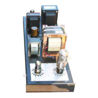
Installing the Interstage Transformer final mechanical installation Interstage transformer – It can only go in one way with the wires feeding into the grommet. At this stage your mono block should similar to the following pictures: Copyright © 2007, 2008 AudioNote Kits Page 15 www.AudioNoteKits.com audionotekits@rogers.com... -
Page 16: Section 3: Iec Section
Section 3: IEC Section IMPORTANT: You will need to look at the AC Wiring Guide in the Appendix to locate the wiring connections for your world voltage (120, 240 etc.). IMPORTANT: Many of the pictures in this manual regarding both the mains transformer’s primary and secondary lead colors are taken from when we used to use the ‘old’... -
Page 17: Connecting Iec And Transformer Grounds
Connecting IEC and Transformer Grounds Step 1 in the IEC section is to take the prepared Green wire and solder it to the GND post on the IEC plug (see graphic) – You will want to strip and tin the end of the wire. Step 2 is to take the long green/yellow wire from the Mains transformer with the GND lug already soldered to it –... -
Page 18: Connecting The Mains Primary To The Rocker Switch
Connecting the Mains Primary to the Rocker Switch As stated earlier, it is important that you wire up the mains in accordance with your required mains voltage that varies in different parts of the world. Please refer to the correct diagram in the AC Wiring Guide in the Appendix at the end of this manual. -
Page 19: Finishing Off The Mains Wiring
Finishing off the mains wiring Take the prepared twisted Brown/Blue wire now and connect the rocker switch to the IEC plug as shown opposite. All the remaining wires on the Primary of the Mains transformer can now be stowed away. Cut off the exposed metal ends of these wires but keep them to length. -
Page 20: Section 4: Completing The Power Supply
Section 4: Completing the Power Supply We are now going to make our first connections from the secondary of the Mains transformers to the 8-pin valve base. Select the twisted pair of yellow wires from the secondary as shown and we will be connecting these to the valve base pins 2 &... -
Page 21: Power Supply Hard-Wiring
Power Supply Hard-Wiring The Power Supply for the Mono Block is hardwired using two hardwire tag strips that you have already installed in your chassis. You will start by installing a pair of 47uf 450v electrolytic capacitors in the manner shown opposite. Bend them down such that they lie along the bottom of the chassis, as we will be installing resistors on top... - Page 22 Note: We have not shown the 47uf caps in this picture for clarity purposes. The next step is to install the prepared ground wire clip. This completes the chassis GND post so it can now be tightened. Add the 100R resistor on the top rail.
- Page 23 Now install a red wire from pin 8 of the 5Y3 (5U4G) 8-pin octal valve base over to the 220K resistor on rail 5 LEFT hand side. Copyright © 2007, 2008 AudioNote Kits Page 23 www.AudioNoteKits.com audionotekits@rogers.com...
- Page 24 Now take a piece of silver wire and shape it such that it can be positioned across Rails 6 -10 on the left hand side. NOTE: Note how the silver wire hangs over the edge – this is a good thing because you can clip onto it as it is the main GROUND for the circuit and very useful for testing DC voltages in the kit later...
- Page 25 We are now going to assemble the rear insert plate that holds the Large Power Supply Capacitors. Start by placing the capacitor clamps as shown in the picture and then secure into position over the holes in the plates with the M4 10mm screws and M4 nuts. Make sure you install on the GOOD side with the countersunk screw holes (shown with red arrows in the picture opposite).
- Page 26 The insert plate can now be screwed into position. Now from the underside of the chassis we are going to connect the capacitors into the power supply section. The black Jensen capacitor with the 220uf 500V marking will use the screw lugs. Locate the + Lug and unscrew, then install the Prepared Red cable into position –...
- Page 27 This diagram shows the top (220uF) capacitor installed and wired up. The second capacitor is actually 2 capacitors in one – It contains 2x 100uf capacitors. The three pins are for 100uF, 100uF and GND. We have soldered the GND pin on the capacitor to the GND section of the hardwiring posts.
- Page 28 This diagram shows the bottom capacitor 'pair' connected. The last step in the power supply is to Ground the center tap from the secondary of the mains transformer – Find the Red/Yellow wire. Trim it and connect to the ground section on the Hardwiring tag. See the pictures below: Congratulations –...
- Page 29 The wires for the O/P transformer and Interstage transformer are not connected yet but everything else should be installed along with the 2x 47uF capacitors. Copyright © 2007, 2008 AudioNote Kits Page 29 www.AudioNoteKits.com audionotekits@rogers.com...
-
Page 30: Additional Wiring For Parallel Triode Operation
Additional Wiring for Parallel Triode Operation The following is only applicable if you are building the Parallel version of the Mono Blocks and should otherwise be ignored. In the parallel Triode Power Supply we need to add the 47K and 330K resistors in order to “raise”... -
Page 31: Section 5: Building And Installing The Filament Board
Section 5: Building and Installing the Filament Board We are now going to build the Filament Board for the Mono Block Kit. The Filament Board takes the AC voltage from the Secondary of the Mains transformer and converts it to the correct DC voltage that the Tubes require. - Page 32 The Filament Board is divided into two sides - each side takes in an AC input voltage regulates it down to the a correct DC filament voltage - The most typical configuration of the mono block is 300B single triode - In this particular case we have one half of the filament board provide a 5v DC for the 300B tube and the other side provides a 6.3v DC for the 6SH7 tube.
- Page 33 Here, you can see the 4 capacitors installed into position. The next step is to install the Twisted wire provided in the kit Filament Kit Bag. Install the Red/Black twisted wire in W1 (Red) and W3 (Black). This is the output of the filament board that will carry the 5V DC to the 300B tube.
- Page 34 The next part we need to concentrate on – the LM1084 regulators need to be installed on the board. They need to inserted a specific length in order that they will meet up with the holes on the Heat Sink. The left-most picture shows the correct length of insertion –...
- Page 35 We are now going to install for a single triode 300B filament configuration - check the chart at beginning of manual for your secondary transformer wires and resistor combinations. For example, Single 2A3 or parallel configurations will differ from the following instructions. If all looks good then go ahead and solder the regulators into position.
- Page 36 Install the Blue wire into W8 and the Black wire into W6. Then solder from underneath the board and clip off the remaining wire protruding through. Do the same with the other pair of wires with W5 (Green) and W7 (Violet). With these wires installed in the Filament Board we cannot install the board into position.
- Page 37 Install the plastic insert onto the M3 x 8, pan head screw and then position into the hole for the regulator – Tighten the screw – now its important that the screw if firmly tight but do not squeeze the daylights out of it or you will break the plastic insert –...
-
Page 38: Section 6: Front Insert Plate And Remaining Wiring
Section 6: Front Insert Plate and Remaining Wiring This is the Front Insert Plate for the Single Triode Mono Block. We will be installing a 4-pin valve Base for the 300B/2A3 triode and an 8-pin valve base for the 6SH7 input tube. A TAG strip will also be installed before beginning work on wiring it all up. - Page 39 On the top side of the Insert plate you can see the 4-pin and 8-pin valve bases installed. Note the orientation of the 300B valve base with the small pins towards the edge of the chassis. The 8-pin valve base has the notch facing towards the left edge of the chassis.
- Page 40 Mark the 4-pin valve base with the numbers. Pin 1 is marked with a pencil and circled in the picture to show you its position. Take the small prepared silver wire and install into the TAG strip. This entire TAG strip will be a GND bus –...
-
Page 41: Wiring The Front Plate
Wiring the Front Plate Please refer to the following wiring diagram. In addition to referring to the above diagram, also refer to your schematic to double check your connections with the pictures and instructions at each stage of the wiring. Copyright ©... - Page 42 Lets start by connecting the 100-ohm (100R) resistor between pins 6 & 8 of the 8-pin valve base (6SH7). Now install the 330R resistor from pin 3 to the GND tag strip. Now install the 470uf 16v capacitor from the same pin 3 on the 6SH7 to the GND bus.
- Page 43 Now you must prepare the two 1K5 wirewound resistors. They are mounted in parallel with each other – see the following sequence: 1. Take the two wirewound resistors. 2. Wrap the leads from one of them around the straight leads of the other. 3.
- Page 44 Install the 1K5 pair between pin 4 of the valve base and the GND clip. Also install the 220uf 100v cap across the resistor from pin 4 to the GND base – ensure that the Negative side of the electrolytic capacitor (220uf 100v) is on the GND tag side. Also add the prepared Black wire to the GND tag.
- Page 45 Install the RCA connector into the front side of the chassis next to the 8-pin valve base. The white insulators are against the chassis – Bend the GND pin on the RCA inward so that it is away from the chassis and you will be able to easily solder to it.
-
Page 46: Filament Wire Connections To 300B And 6Sh7
Now notice the 100K resistor goes from the input to GND – wrap it around the input side of the 1K resistor we just installed and connect the other end to the GND Tag strip. The two resistors we have just installed appear as follows (highlighted in yellow) on the signal path schematic. -
Page 47: Output Transformer Primary Connections
Output Transformer Primary Connections With the filaments installed – lets now install the output transformer wires – these are the primaries – the RED wire as shown will connect to pin 2 of the 300B. Then take the other black wire from the output transformer primary and stretch it the other way across the chassis –... -
Page 48: Interstage Transformer Wiring
Now take the Black wire that you attached to the TAG strip on the front insert plate and stretch it down to connect to the GND bus on the power supply (Zig-Zag silver wire). Interstage Transformer Wiring You will see 4 different colored wires coming out of the Interstage transformer –... - Page 49 Let’s start by installing the 3K3 resistor with Heat shrink onto pin 3 of the 300B valve base – see the following sequence: Now to connect the white wire from the interstage transformer. First, the wire must be extended to enable it to reach - so lets start by extending the white wire from the Interstage transformer.
- Page 50 Finally, wrap the end of the extended white wire around the resistor 3K3 we were just working with (make sure you have some more heat shrink on the wire before you wrap) and solder so that you can cover the exposed area. Copyright ©...
- Page 51 Here you can see the completed connection of the white wire from the Interstage transformer. It was extended and then connects to the 3K3 resistor connecting to the 300 B Valve base. With the white wire in position – now connect the RED wire from the interstage to the 8-pin valve base on the front insert plate.
- Page 52 See the black wire position as it connects to the 15K resistor. Then the last wire - the BLUE wire you will need to extend with purple wire and connect to the GND tag on the Front insert plate. Copyright © 2007, 2008 AudioNote Kits Page 52 www.AudioNoteKits.com audionotekits@rogers.com...
-
Page 53: Input Signal Earth Connection
Input Signal Earth Connection With the four wires from the interstage connected you need to connect a black wire from the GND on the RCA to the Tag strip on the insert plate. Speaker Post Installation Install the two speaker posts into the kit as shown aboe – Connect the red one closest to the front of the chassis – Make sure that the plastic insulation is touching the chassis an no metal parts! For 8 ohm operation For 4 ohm operation... -
Page 54: Tidying Up
Tidying Up You will want to clean up the unused transformer wire – A good method is to add heat shrink to the ends (clip the ends first so that no metal is exposed) and then add heat shrink and tie wrap the bundle together – then position in the chassis such that it will not come in contact with other circuitry. -
Page 55: Section 7: Final Checks, Testing, And Finishing Off
Section 7: Final Checks, Testing, and Finishing Off We will now move into the checklist to make sure that all our wiring is correct followed by the turn on procedure. Congratulations on getting to this point!!!! Mono Block Wiring Check List It is very important now to check over all your wiring –... - Page 56 Copyright © 2007, 2008 AudioNote Kits Page 56 www.AudioNoteKits.com audionotekits@rogers.com...
-
Page 57: Checklist
Checklist Go through all these checks and check off that they are as listed… Output Transformer Primaries Black wire 15K resistor on PS (see graphic below) Red wire Pin 2 300B Interstage Transformer Pin 8 of 6SH7 White To 3K3 resistor that connects to pin 3 of 300B Blue GND tag strip on Front Insert Plate Black... - Page 58 300B Valve Base Pin 1 Red wire to Filament board W1 Pin 2 Red wire Primary of O/P Transformer Pin 3 3K3 resistor white to white wire back to Interstage transformer Pin 4 Black wire to Filament board W3 1K5 parallel resistors (whose other ends go to GND) 220uf 100v capacitor (whose other end goes to GND) 6SH7 8-pin Valve Base Pin 1...
-
Page 59: Resistance Checks
5Y3 Valve Base Not connected Pin 1 Pin 2 Yellow wire to Mains transformer secondary Pin 3 Not connected Pin 4 Red wire to Mains transformer secondary (for 300B operation) - or - Orange wire to Mains transformer secondary (for 2A3 operation) Pin 5 Not connected Pin 6... -
Page 60: Switching On And Testing
Switching On and Testing If you are feeling confident that you have a good build then I would suggest inserting a 2A fuse (provided) into the fuse holder in the IEC socket. Do not install any tubes yet. I would now try powering on the amp to see if the fuse blows. If all ok then install the 300B and the 6SH7 tubes into position and power on again –... -
Page 61: Mono Block Testing Kit
When you turn on the amplifier – if all the tubes light up and all is well then we need to check a couple of key voltages to make sure all is well… Check pin 8 of the 6SH7 – it should be 180V-190v DC. •... -
Page 62: Fitting The Feet And Base Plate
Fitting the Feet and Base Plate Install the large rubber feet onto the base plate on the side with the countersunk holes. Use the fender washer on the bottom of the foot and the M4 16mm screw – on the other side of the base plate use a serrated M4 washer and a M4 Nut. -
Page 63: Final Thoughts
Enjoy your new amplifiers. If you have any questions or feedback for us please contact us on audionotekits@rogers.com Regards Brian Smith and the Audio Note Design Team Copyright © 2007, 2008 AudioNote Kits Page 63 www.AudioNoteKits.com audionotekits@rogers.com... -
Page 64: Appendix
Appendix The appendix contains auxiliary information. That is information that is either common to most project manuals or any last minute pieces of information that did not make it into the manual in time. It may also contain pull-out circuit diagrams that may be handy to have outside the manual etc. -
Page 65: Resistor Color Code Reference
Resistor Color Code Reference You can also find an 'Interactive Resistor Color Code Calculator' on our website (available from the Links page). Copyright © 2007, 2008 AudioNote Kits Page 65 www.AudioNoteKits.com audionotekits@rogers.com... -
Page 66: Ac Wiring Guide (Mk3 Mains Transformer)
AC Wiring Guide (Mk3 Mains Transformer) The following diagrams show the mains wiring configurations for the various world voltages. It is recommended that you cross out the ones that don't apply to you so that you can't follow the wrong one. Copyright ©... -
Page 67: Front Plate Wiring Diagram
Front Plate Wiring Diagram Copyright © 2007, 2008 AudioNote Kits Page 67 www.AudioNoteKits.com audionotekits@rogers.com... -
Page 68: Power Supply Schematic (Mk3 Mains Transformer)
Power Supply Schematic (Mk3 Mains Transformer) Copyright © 2007, 2008 AudioNote Kits Page 68 www.AudioNoteKits.com audionotekits@rogers.com... -
Page 69: Signal Path Schematic (Single 300B)
Signal Path Schematic (Single 300B) Copyright © 2007, 2008 AudioNote Kits Page 69 www.AudioNoteKits.com audionotekits@rogers.com... -
Page 70: Signal Path Schematic (Parallel 300B)
Signal Path Schematic (Parallel 300B) Copyright © 2007, 2008 AudioNote Kits Page 70 www.AudioNoteKits.com audionotekits@rogers.com...
Need help?
Do you have a question about the Mono Block 300b/2A3 and is the answer not in the manual?
Questions and answers