Icom IC-F60 Instruction Manual
Uhf transceiver
vhf transceiver
Hide thumbs
Also See for IC-F60:
- Instruction manual (68 pages) ,
- Service manual (78 pages) ,
- Insrtuction manual (64 pages)

Subscribe to Our Youtube Channel
Related Manuals for Icom IC-F60


Summary of Contents for Icom IC-F60
- Page 1 INSTRUCTION MANUAL VHF TRANSCEIVER iF50 UHF TRANSCEIVER iF60 This device complies with Part 15 of the FCC rules. Operation is subject to the condition that this device does not cause harmful interference.
-
Page 2: Safety Training Information
“General Population” in an uncontrolled environment. This radio has been tested and complies with the FCC RF exposure limits for “Occupational Use Only”. In addition, your Icom radio complies with the following Standards and Guidelines with regard to RF energy and electromagnetic energy levels and evaluation of such levels for exposure to humans: •... - Page 3 “PTT” switch. • ALWAYS keep the antenna at least 2.5 cm (1 inch) away from the body when transmitting and only use the Icom belt-clip which is listed on page vi when attaching the radio to your belt, etc., to en- sure FCC RF exposure compliance requirements are not exceeded.
-
Page 4: Foreword
2.5 centimeters (1 inch) from your body when transmitting. Icom, Icom Inc. and the Icom logo are registered trademarks of Icom Incorpo- rated (Japan) in the United States, the United Kingdom, Germany, France, Spain, Russia and/or other countries. -
Page 5: Precaution
*Only when BP-227/FM is attached. FCC caution: Changes or modifications to this device, not expressly approved by Icom Inc., could void your authority to operate this transceiver under FCC regulations. -
Page 6: Table Of Contents
TABLE OF CONTENTS SAFETY TRAINING INFORMATION ..........i–ii FOREWORD ..................iii EXPLICIT DEFINITIONS ..............iii OPERATING NOTES................iii PRECAUTION ..................iv TABLE OF CONTENTS ............... v SUPPLIED ACCESSORIES ............... vi 1 ACCESSORIES ................1–2 . . Accessory attachments ..............1 2 PANEL DESCRIPTION .............. 3–11 . -
Page 7: Supplied Accessories
5 BATTERY CHARGING ............35–44 . Battery charging ................. 35 . Caution ..................36 . Optional battery chargers ............37 . Optional battery case..............43 6 SPEAKER-MICROPHONE ............45–46 . Optional HM-169/170GP description .......... 45 . Attachment ................. 46 7 OPTIONS ................. 47–48 SUPPLIED ACCESSORIES The following accessories are supplied: Qty. -
Page 8: Accessories
ACCESSORIES . Accessory attachments D Flexible antenna Connect the supplied flexible antenna to the antenna connector. CAUTION: • NEVER HOLD the antenna when carrying the transceiver. • Transmitting without an antenna may damage the transceiver. D Battery pack To attach the battery pack: Slide the battery pack on the back of the transceiver in the direction of the arrow (q), then lock it with the battery release button. -
Page 9: Accessories
ACCESSORIES D Jack cover Attach the jack cover when the optional speaker-microphone is not used. To attach the jack cover: To detach the jack cover: q Insert the jack cover into the e Unscrew the screw with a [SP MIC] connector. phillips screwdriver. -
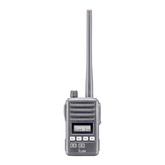
Page 10: Panel Description
PANEL DESCRIPTION . Front, top and side panels Speaker (See the following NOTE.) Microphone Function display (p. 6) NOTE: If the speaker netting (for dust proofing) becomes wet, dry it with a hair drier (cool mode) etc. before operating the transceiver. - Page 11 PANEL DESCRIPTION q VOLUME CONTROL [VOL] Turns power ON and adjusts the audio level. w RED BUTTON The desired function can be assigned by your dealer. e ANTENNA CONNECTOR Connects the supplied antenna. r SPEAKER-MICROPHONE CONNECTOR [SP MIC] Connects the optional speaker-microphone. (p. 46) [SP MIC] jack cover NOTE: KEEP the [SP MIC] jack cover attached to the...
- Page 12 PANEL DESCRIPTION u TRANSMIT/BUSY INDICATOR Lights red while transmitting; lights green while receiving a sig- nal, or when the squelch is open. i PTT SWITCH [PTT] Push and hold to transmit; release to receive.
-
Page 13: Function Display
PANEL DESCRIPTION . Function display q OUTPUT POWER INDICATOR Appears when Low 2 or Low 1 is selected. w AUDIBLE INDICATOR ➥ Appears when the channel is in the ‘audible’ (unmute) condi- tion. ➥ Appears when the specified 2/5-tone/BIIS code is received. e COMPANDER INDICATOR Appears when the compander function is activated. -
Page 14: Programmable Function Keys
[Red], [ ] and [ ] programmable function keys. Consult your Icom dealer or system operator for details concern- ing your transceivers programming. If the programmable function names are bracketed in the following explanations, the specific switch used to activate the function de- pends on programming. - Page 15 PANEL DESCRIPTION PRIORITY CHANNEL KEYS ➥ Push to select Priority A or Priority B channel. ➥ Push and hold [Prio A (Rewrite)] to rewrite the Prio A channel. MR-CH 1/2/3/4 KEYS Select an operating channel directly. MONITOR KEY ➥ Mute and release the CTCSS (DTCS) or 2-tone squelch mute. Open any squelch/deactivate any mute while pushing this key.
- Page 16 PANEL DESCRIPTION C.TONE CHANNEL ENTER KEY Select the continuous tone channel using [CH Up]/[CH Down] keys to change the tone frequency/code setting after pushing this key for permanent operation. TALK AROUND KEY Turn the talk around function ON and OFF. •...
- Page 17 PANEL DESCRIPTION EMERGENCY KEYS ➥ Push and hold to transmit an emergency call. ➥ When [Emergency Single (Silent)] or [Emergency Repeat (Si- lent)] is pushed, an emergency call is transmitted without a beep emission and LCD indication change. • If you want to cancel the emergency call, push (or push and hold) the key again before transmitting the call.
-
Page 18: Panel Description
PANEL DESCRIPTION VOICE SCRAMBLER FUNCTION Push to toggle the voice scrambler function ON and OFF. COMPANDER KEY Push to toggle the compander function ON and OFF. The compander function reduces noise components from the transmitting audio to provide clear communication. USER SET MODE KEY ➥... -
Page 19: Conventional Operation
CONVENTIONAL OPERATION . Turning power ON q Rotate [VOL] to turn power ON. w If the transceiver is programmed for a start up passcode, input digit codes as directed by your dealer. • The keys in the table below can be used for password input: •... -
Page 20: Call Procedure
CONVENTIONAL OPERATION . Call procedure When your system employs tone signalling (excluding CTCSS and DTCS), the call procedure may be necessary prior to voice trans- mission. The tone signalling employed may be a selective calling system which allows you to call specific station(s) only and prevent unwanted stations from contacting you. -
Page 21: Receiving And Transmitting
CONVENTIONAL OPERATION . Receiving and transmitting NOTE: Transmitting without an antenna may damage the trans- ceiver. See p. 1 for antenna attachment. Receiving: q Rotate [VOL] to turn power ON. w Push [ ] or [ ] to select a channel. e When receiving a call, adjust the audio output level to a com- fortable listening level. -
Page 22: D Transmitting Notes
CONVENTIONAL OPERATION D Transmitting notes • Transmit inhibit function The transceiver has several inhibit functions which restrict trans- mission under the following conditions: - The channel is in mute condition (‘Inaudible’ condition; “ ” does not appear). - Channel is busy. - Un-matched (or matched) CTCSS is received. - Page 23 CONVENTIONAL OPERATION D TX code number edit (PMR or BIIS PMR operation only) If the transceiver has [TX Code CH Select] or [TX Code Enter] as- signed to it, TX code contents can be edited within the allowable digits. TO EDIT A TX CODE VIA [TX CODE CH SELECT] KEY: q Push [TX Code CH Select] to enter the TX code channel selec- tion mode.
-
Page 24: Scrambler Function
CONVENTIONAL OPERATION D DTMF transmission If the transceiver has [DTMF Autodial] assigned to it, the automatic DTMF transmission function is available. Up to 8 DTMF channels are available. TO SELECT A TX CODE: q Push [DTMF Autodial]— a DTMF channel appears. w Push [ ] to select the desired DTMF channel. -
Page 25: User Set Mode
CONVENTIONAL OPERATION . User set mode User set mode is accessed at power ON and allows you to set seldom-changed settings. In this case you can “customize” trans- ceiver operation to suit your preferences and operating style. Entering the user set mode: q While pushing and holding [ ] and [ ], rotate [VOL] to... -
Page 26: Biis Operation
BIIS OPERATION . Default setting The following functions are assigned to each programmable switch as the default. Ask your dealer for details. [P0]; Call : Push to transmit a 5-tone/BIIS call when the selected channel is a 5-tone or MSK chan- nel, respectively. -
Page 27: Receiving A Call
BIIS OPERATION . Receiving a call D Individual call q When an individual call is received; • Beeps sound. • “ ” appears and the mute is released. • The programmed text message (e.g.“ ”) and the calling station ID (or text) is displayed alternately, depending on the set- ting. -
Page 28: D Group Call
BIIS OPERATION D Group call q When a group call is received; • Beeps sound. • “ ” appears and the mute is released. • The programmed text message (e.g.“ ”) and the calling sta- tion ID (or text) is displayed alternately, depending on the setting. •... -
Page 29: D Displaying The Received Call Record
BIIS OPERATION D Displaying the received call record — Queue indication The transceiver memorizes the calling station IDs for record. Up to 3 calls can be memorized, and the oldest call record is erased when a 4th call is received. However, once the transceiver is pow- ered OFF, the all records are cleared. -
Page 30: Transmitting A Call
BIIS OPERATION . Transmitting a call Total of a 3 ways for code selection are available—selecting the call code from memory, entering the call code from the keypad and calling back from the queue channel record. D Using call memory q While in the standby condition, push [P1] (Digital) to enter the call code memory channel selection mode. -
Page 31: D Calling Back From The Queue Channel
BIIS OPERATION D Calling back from the queue channel q While in the standby condition, push [P1] (Digital) for 1 sec. to enter queue memory channel selection mode. w Push [ ] to select the desired record. e Push [P0] (Call) or [PTT]* to call. *PTT call can be made only when PTT call capability is permitted. -
Page 32: D Direct Code Entry
BIIS OPERATION D Direct code entry q While in the standby condition, push [TX Code Enter] to enter the TX code edit mode. • Editable code digit blinks. w Push [TX Code Enter] to select the desired digit to be edited. •... -
Page 33: Receiving A Message
BIIS OPERATION . Receiving a message D Receiving a status message q When a status message is received; • Beeps sound. • The calling station ID (or text) and the status message is displayed alternately, depending on the setting. w Push [P3] (Moni(Audi)) to return to the standby condition. NOTE: Only the calling station ID (or text) is displayed (no message is displayed alternately) when the scroll timer is set to “OFF”. - Page 34 BIIS OPERATION D Receiving an SDM q When an SDM is received; • Beeps sound. • The calling station ID (or text) and the SDM is displayed alter- nately, depending on the setting. w When the received SDM includes more than 8 characters, the message scrolls automatically, when the automatic scroll func- tion is activated.
-
Page 35: D Received Message Selection
BIIS OPERATION D Received message selection The transceiver memorizes the received messages for record. Up to 6 messages for status and SDM, or 95 character SDM’s can be memorized. The oldest message is erased when the 7th message is received. However, once the transceiver is powered OFF, all messages are cleared. -
Page 36: Transmitting A Status
BIIS OPERATION . Transmitting a status D General The status message can be selected with the programmed text, and the message text is also displayed on the function display of the called station. Up to 24 status types (1 to 24) are available, and the status mes- sages 22 and 24 have designated meanings. -
Page 37: Transmitting An Sdm
BIIS OPERATION . Transmitting an SDM D General The short data message, SDM, can be sent to an individual sta- tion or group stations. Also, 8 SDM memory channels are available and the messages can be edited via PC programming. D Transmitting an SDM q While in the standby condition, push [P1] (Digital), then push ] to select the desired station/group code. -
Page 38: Position Data Transmission
BIIS OPERATION . Position data transmission When the optional OPC-966 and a GPS receiver interface cable is connected to the transceiver, the position (longitude and lati- tude) data can be transmitted automatically. Ask your dealer or system operator for connection details. The position data is transmitted when;... -
Page 39: Printer Connection
BIIS OPERATION . Printer connection When the optional OPC-966 is connected to the interface cable transceiver, a printer can be connected to print out the received SDM content and the ID of the station who sent the message. Ask your dealer or system operator for connection details. . -
Page 40: Auto Emergency Transmission
BIIS OPERATION . Auto emergency transmission When [Emergency Single (Silent)] or [Emergency Repeat (Silent)] is pushed, an emergency signal is automatically transmitted for the specified time period. The status 22 (Emergency) is sent to the selected ID station, and the position data is transmitted after the emergency signal when a GPS receiver is connected to the transceiver. -
Page 41: Biis Indication
BIIS OPERATION . BIIS indication The following indications are available for the BIIS operation on an MSK channel. : Individual/group call is successful. : Message (status or SDM) transmission is successful. : No answer back is received. : Appears during retry of the call (2nd call). : End the communication. -
Page 42: Battery Charging
BATTERY CHARGING . Battery charging Prior to using the transceiver for the first time, the battery pack must be fully charged for optimum life and operation. CAUTION: To avoid damage to the transceiver, turn it OFF while charging. • Recommended temperature range for charging: BC-190/BC-119N/BC-121N : +10°C to +40°C (+50°F to +104°F) BC-152 : 0°C to +45°C (+32°F to +113°F) -
Page 43: Caution
BATTERY CHARGING . Caution CAUTION! NEVER insert battery pack/transceiver (with the battery pack attached) with wet or soiled into the charger. This may result in corrosion of the charger terminals or damage to the charger. The charger is not waterproof and water can easily get into it. -
Page 44: Optional Battery Chargers
BATTERY CHARGING . Optional battery chargers D Regular charging with the BC-152 q Attach the BC-152 to a flat surface, such as a desk, if desired. w Connect the AC adapter as shown below. e Insert the battery pack with/without the transceiver into the charger. •... - Page 45 BATTERY CHARGING D Rapid charging with the BC-190 q Attach the BC-190 to a flat surface, such as a desk, if desired. w Connect the AC adapter as shown below. e Insert the battery pack with/without the transceiver into the charger. •...
- Page 46 BATTERY CHARGING D For your convenience Eyelet USE a rubber band to secure the transceiver while charging, if desired.
- Page 47 BATTERY CHARGING D AD-100 installation The AD-100 must be installed into the BC-119N charger adapter or BC-121N before battery charging. ➥ Connect the AD-100 and the BC-119N/BC- charger adapter 121N as below, then install the AD-100 into the holder space of the BC-119N or BC-121N with the supplied screws.
- Page 48 BATTERY CHARGING D Rapid charging with the BC-119N+AD-100 The optional BC-119N provides rapid charging of optional Li-Ion battery packs. The followings are additionally required: • One AD-100 (purchase separately) • An AC adapter (may be supplied with BC-119N depending on version) or the DC power cable (OPC-515L/CP-17L).
- Page 49 BATTERY CHARGING D Rapid charging with the BC-121N+AD-100 The optional BC-121N allows up to 6 battery packs to be charged simultaneously. The followings are additionally required. • Six AD-100. • An AC adapter (BC-157) or the DC power cable (OPC-656) Transceiver Turn power OFF Battery pack...
-
Page 50: Optional Battery Case
BATTERY CHARGING . Optional battery case When using the optional battery case attached to the transceiver, install 5 × AA (LR6) size alkaline batteries as illustrated at right. The BP-226 is constructed to the IPX4 waterproof standard (IEC 60529, 2006). q Hook your finger under the latch, and open the cover in the direc- tion of the arrow (q). -
Page 51: Battery Charging
BATTERY CHARGING Latch BP-226 Fig.1 Fig.2 Ribbon Fig.3 Gasket Ribbon... -
Page 52: Speaker-Microphone
SPEAKER-MICROPHONE . Optional HM-169/170GP description TOP KEY* GPS ANTENNA (for HM-160GP only) (for HM-170GP only) *Not available for the Microphone IC-F50/F60 series transceivers. Speaker Belt clip PTT SWITCH Push and hold to transmit; release to receive. Turn the transceiver power OFF while connecting the HM-169/170GP. -
Page 53: Attachment
SPEAKER-MICROPHONE . Attachment Attach the connector of the speaker-microphone into the [SP MIC] connector on the transceiver and tighten the screw with a coin or flat head screwdriver. CAUTION: Attach multi connector snugly, but do not overtighten. A loose connection will al- low water intrusion into the connector;... -
Page 54: Options
OPTIONS D BATTERY PACK/CASE • BP-226 battery case Battery case for 5 × AA (LR6) alkaline cells. The BP-226 meets IPX4 requirements for splash resistance*. When it is connected, the transceiver corresponds to IPX4. • BP-227/FM battery pack Voltage : 7.4 V Capacity : 1850 mAh (minimum)/1950 mAh (typical) BP-227/FM must be charged with the optional BC-152/BC-190/BC- 119N/BC-121N. -
Page 55: Belt Clip
* Once these items have been dropped, the IP rating or waterproof protection cannot be guaranteed because of possible damage to these cases or the waterproof seals. Icom optional equipment is designed for optimal performance when used with this transceiver. We are not responsible for the transceiver being damaged or any accident caused when using non-Icom optional equipment. - Page 56 A-6294H-1EX-o Printed in Japan © 2003–2009 Icom Inc. 1-1-32 Kamiminami, Hirano-ku, Osaka 547-0003, Japan Printed on recycled paper with soy ink.
Need help?
Do you have a question about the IC-F60 and is the answer not in the manual?
Questions and answers