Table of Contents
Advertisement
INSTRUCTION MANUAL
VHF TRANSCEIVERS
iF3021T/S
iF3023T/S
iF3026T/S
UHF TRANSCEIVERS
iF4021T/S
iF4023T/S
iF4026T/S
This device complies with Part 15 of the FCC
Rules. Operation is subject to the condition that
this device does not cause harmful interference.
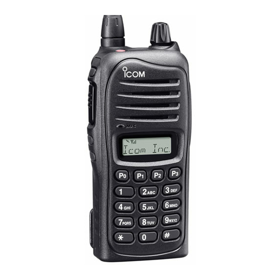
The photo shows the 10-key
version VHF transceiver.
Advertisement
Table of Contents

Related Manuals for Icom IC-F3021T/S


Summary of Contents for Icom IC-F3021T/S
- Page 1 INSTRUCTION MANUAL VHF TRANSCEIVERS iF3021T/S iF3023T/S iF3026T/S UHF TRANSCEIVERS iF4021T/S iF4023T/S iF4026T/S This device complies with Part 15 of the FCC Rules. Operation is subject to the condition that this device does not cause harmful interference. The photo shows the 10-key version VHF transceiver.
-
Page 2: Explicit Defenitions
2 to 4 in. (5 instruction manual contains important operating instruc- to 10 cm) away from the lips and the transceiver is vertical. tions for the IC-F3021T/S, IC-F3023T/S, IC-F3026T/S VHF R CAUTION! NEVER TRANSCEIVERS and the IC-F4021T/S, IC-F4023T/S, IC- operate the transceiver with a... -
Page 3: Fcc Information
• Reorient or relocate the receiving antenna. CAUTION: Changes or modifications to this transceiver, not • Increase the separation between the equipment and re- expressly approved by Icom Inc., could void your authority to ceiver. operate this transceiver under FCC regulations. -
Page 4: Table Of Contents
TABLE OF CONTENTS IMPORTANT ................i 4 OPTIONAL SmarTrunk OPERATION .....16−17 EXPLICIT DEFENITIONS ............. i ■ SmarTrunk 3G™ mode selection .......16 PRECAUTIONS ..............i ■ SmarTrunk 3G™ operation .........16 5 BATTERY CHARGING ..........18−21 FCC INFORMATION ............ii TABLE OF CONTENTS ............iii ■ Caution ...............18 1 ... -
Page 5: Accessories
ACCESSORIES ■ Supplied accessories ■ Accessory attachments NOTE: Some accessories are not supplied with depend- D Flexible antenna ing on versions. Connect the supplied flexible antenna to the antenna connector. Flexible antenna Battery pack Belt clip CAUTION! • NEVER HOLD the antenna when carrying the transceiver. •... - Page 6 ACCESSORIES D Battery pack D Belt clip To attach the battery pack: To attach the belt clip: Slide the battery pack in the direction of the arrow (q), then q Release the battery pack if it is attached. lock it with the battery release button. w Slide the belt clip in the direction of the arrow until the belt •...
- Page 7 ACCESSORIES D Jack cover Attach the jack cover when the optional speaker-microphone or headset is not used. To detach the jack cover: To attach the jack cover: q Attach the jack cover to the [MIC/SP] jack. q Unscrew the screws using a phillips screwdriver. w Detach the jack cover for the speaker-microphone or w Tighten the screws.
-
Page 8: Panel Description
PANEL DESCRIPTION ■ Front panel e DEALER-PROGRAMMABLE KEY [Side1] Desired function can be programmed by your dealer. (p. 7) r PTT SWITCH [PTT] Push and hold to transmit; release to receive. t DEALER-PROGRAMMABLE KEYS [Side2]/[Side3] Desired functions can be programmed independently by Speaker your dealer. (p. 7) Microphone y 10-KEYPAD (Depending on version) The keypad allows you to enter digits to: •... - Page 9 PANEL DESCRIPTION o EXTERNAL MICROPHONE/SPEAKER JACK Connect an optional speaker-microphone or headset. NOTE: Connect or disconnect the optional equipment after the transceiver is turned OFF. Jack cover NOTE: Attach the jack cover when the optional equipment is not used. See (p. 3) for details. !0 VOLUME CONTROL [VOL] Rotate to turn the power ON/OFF and adjusts the audio level.
-
Page 10: Function Display
PANEL DESCRIPTION ■ Function display y SCRAMBLER INDICATOR Appears when the voice scrambler function is activated. u BELL INDICATOR Appears/blinks when the specific 2-tone code is received, according to the pre-programming. i KEY LOCK INDICATOR Appears during the key lock function is ON. o BATTERY INDICATOR q TRANSMIT INDICATOR Appears or blinks when the battery power decreases to a Appears while transmitting. -
Page 11: Programmable Function Keys
➥ This key’s operation depends on the Power ON Scan set- ting. function keys. When the power ON scan function is turned OFF; Consult your Icom dealer or system operator for details con- Push to start and cancel scanning operation. In case of cerning your transceivers programming. transmission during scan, scanning will be cancelled. - Page 12 PANEL DESCRIPTION PRIO A/B KEYS TALK AROUND KEY ➥ Push to select Priority A or Priority B channel. Push to turn the talk around function ON and OFF. ➥ Push and hold [Prio A (Rewrite)] or [Prio B (Rewrite)] for •...
- Page 13 PANEL DESCRIPTION EMERGENCY KEYS USER SET MODE KEY Push and hold to transmit the emergency call. ➥ Push and hold for 1 sec. to enter user set mode. • The transceiver can transmit the emergency call silently or audibly • During user set mode, push this key to select an item, and depending on the pre-setting.
-
Page 14: Basic Operation
BASIC OPERATION ■ Turning power ON D Battery type selection Prior to using the transceiver for the first time, the battery pack must be fully charged for optimum life and operation. The battery type must be selected according to the attaching (p. 18) battery type when turning the transceiver ON. Ask your dealer for details. -
Page 15: Channel Selection
BASIC OPERATION ■ Channel selection ■ Call procedure Several types of channel selections are available. Methods When your system employs tone signaling (excluding CTCSS may differ according to your system set up. and DTCS), the call procedure may be necessary prior to voice transmission. -
Page 16: Receiving And Transmitting
BASIC OPERATION ■ Receiving and transmitting D Transmitting notes N OTE: Transmitting without an antenna may damage the transceiver. See page 1 for accessory attachments. • Transmit inhibit function The transceiver has several inhibit functions which restrict Receiving: transmission under the following conditions: q Rotate [VOL] to turn the power ON. - The channel is in mute condition (‘Inaudible’... - Page 17 BASIC OPERATION D TX code channel selection D DTMF transmission If the transceiver has [TX Code CH Select] assigned to it, If the transceiver has [DTMF Autodial] assigned to it, the the indication can be toggled between the operating channel automatic DTMF transmission function is available. Up to 8 number (or name) and TX code channel number (or name).
-
Page 18: User Set Mode
BASIC OPERATION ■ User set mode ■ Emergency Call User set mode is accessed at power ON and allows you to The emergency call can be performed using [Emergency]. set seldom-changed settings. In this case you can “custom- (p. 9) ize” the transceiver operation to suit your preferences and The transceiver will send a DTMF, 5-tone or MDC 1200 emer- operating style. -
Page 19: Scrambler Function
BASIC OPERATION ■ Scrambler function ■ MDC 1200 system operation D Receiving an Emergency Call The voice scrambler function provides private communica- tion between stations. The optional Rolling or Non-rolling q When an emergency call is received; type can be available. • Beeps sound. • The calling station alias and “EMG EMG” are displayed alter- q Push [Scrambler] to turn the scrambler function ON. -
Page 20: Optional Smartrunk Operation
OPTIONAL SmarTrunk OPERATION ■ S marTrunk 3G™ mode D Last number re-dial* Push [M] 2times to automatically re-dial the last called selection number. • A high-pitched beep indicates that the number is accepted. This transceiver is capable of SmarTrunk 3G™ functions. Available for 4-key version when the [M] or [#] key function is as- The optional UT-117R allows communication in conventional signed to any programmable key. - Page 21 OPTIONAL SmarTrunk OPERATION D Calling another local system subscriber* D System busy indication Enter the subscriber number followed by [3], [M]. If all channels are busy, three low beeps sound after you ini- • A high-pitched beep indicates that the number is accepted. tiate a call. Try the call again later. •...
-
Page 22: Battery Charging
Icom radios or Icom charger. Only Icom battery seawater, or any other liquids. Never charge or use a wet packs are tested and approved for use and charge with Icom battery. If the battery gets wet, be sure to wipe it dry before radios or Icom charger. - Page 23 D Charging caution abnormal odor, heats up, or is discolored or deformed. If any R DANGER! NEVER charge the battery pack in areas with of these conditions occur, contact your Icom dealer or dis- extremely high temperatures, such as near fires or stoves, tributor.
-
Page 24: Optional Battery Chargers
BATTERY CHARGING ■ Optional battery chargers D AD-106 installation D Rapid charging with the BC-160 The AD-106 must be installed into the The optional BC-160 provides rapid charging of optional Li- charger adapter BC-119N or BC-121N before battery charging. Ion battery packs. • An AC adapter (may be supplied with BC-160 depending ➥... - Page 25 BATTERY CHARGING D Rapid charging with the BC-119N+AD-106 D Rapid charging with the BC-121N+AD-106 The optional BC-119N provides rapid charging of battery The optional BC-121N allows up to 6 battery packs to be packs. The following items are additionally required. charged simultaneously. The following items are additionally • AD-106 charger adapter required.
-
Page 26: Battery Case
BATTERY CASE ■ Optional battery case (BP-240) When using the optional battery case, install 6 × AAA (LR03) Fig.1 size alkaline batteries as illustrated at right. BP-240 q Unhook the battery cover release hook (q), and open the cover in the direction of the arrow (w). (Fig.1) w Then, install 6 ×... -
Page 27: Optional Swivel Belt Clip
OPTIONAL SWIVEL BELT CLIP ■ MB-93 contents e Clip the belt clip to a part of your belt. And insert the transceiver into the belt clip until the base clip inserted fully into the groove. Qty. q Belt clip ................1 w Base clip .................1 ■... -
Page 28: Detaching
OPTIONAL SWIVEL BELT CLIP ■ Detaching w Release the battery pack if it is attached. (p. 2) q Turn the transceiver upside down in the direction of the arrow and pull out from the belt clip. e Pinch the clip (q), and slide the base clip in the direction of the arrow (w). -
Page 29: Options
OPTIONS D BATTERY PACK D BELT CLIPS • MB-93 swivel belt clip Battery pack Voltage Capacity Battery life* • MB-94 belt clip BP-230N 7.4 V 980 mAh 7.35 hrs. Exclusive alligator-type belt clip. The same as supplied with the transceiver. BP-232N 7.4 V 2000 mAh 15.5 hrs. - Page 30 OPTIONS D OTHER OPTIONS • SP-13 earphone Provides clear receive audio in noisy environment. • HM-158L/159L speaker microphone Combination speaker-microphone that provides convenient operation while hanging the transceiver from your belt. • HS-94/HS-95/HS-97 + VS-1L headset ptt case HS-94: Ear-hook type HS-95: Neck-arm type HS-97: Throat microphone VS-1L: VOX/PTT switch box for hands-free operation, etc.
-
Page 31: Safety Training Information
This radio has been tested and complies with the FCC RF exposure FCC RF exposure compliance requirements to be exceeded. The limits for “Occupational Use Only”. In addition, your Icom radio com- radio is transmitting when the TX indicator lights red. You can plies with the following Standards and Guidelines with regard to RF cause the radio to transmit by pressing the “PTT”... - Page 32 A-6506D-1EX-t Printed in Japan © 2006–2008 Icom Inc. 1-1-32 Kamiminami, Hirano-ku, Osaka 547-0003, Japan Printed on recycled paper with soy ink.
Need help?
Do you have a question about the IC-F3021T/S and is the answer not in the manual?
Questions and answers