Table of Contents
Advertisement
Quick Links
Advertisement
Table of Contents

Related Manuals for Supermicro X10DAL-i


Summary of Contents for Supermicro X10DAL-i
- Page 1 X10DAL-i USER’S MANUAL Revision 1.0...
- Page 2 This product, including software and docu- mentation, is the property of Supermicro and/or its licensors, and is supplied only under a license. Any use or reproduction of this product is not allowed, except as expressly permitted by the terms of said license.
-
Page 3: Preface
(Socket R3) that offer Intel Microarchitecture 22nm Processing Technology, delivering performance, power efficiency, and feature sets optimized for small-form factor workstation platforms. With the PCH C612 built in, the X10DAL-i motherboard supports Intel® Node Manager 3.0, Intel® Management Engine, Intel® Thunderbolt Technology, and 2133 MHz DDR4 memory. -
Page 4: Conventions Used In The Manual
X10DAL-i Motherboard User's Manual Conventions Used in the Manual Pay special attention to the following symbols for proper system installation and to prevent damage to the system or injury to yourself: Warning: Important information given to ensure proper system installation or to avoid damaging the components or the motherboard, Note: Additional important information provided for correct system setup. -
Page 5: Contacting Supermicro
Super Micro Computer, Inc. 980 Rock Ave. San Jose, CA 95131 U.S.A. Tel: +1 (408) 503-8000 Fax: +1 (408) 503-8008 Email: marketing@supermicro.com (General Information) support@supermicro.com (Technical Support) Website: www.supermicro.com Europe Address: Super Micro Computer B.V. Het Sterrenbeeld 28, 5215 ML... -
Page 6: Table Of Contents
Conventions Used in the Manual .................. 4 Contacting Supermicro ....................5 Chapter 1 Overview Overview ......................1-1 Checklist ......................1-1 X10DAL-i Quick Reference ................1-4 Motherboard Features ..................1-7 Processor and Chipset Overview..............1-11 Special Features ................... 1-12 Recovery from AC Power Loss ..............1-12 System Health Monitoring ................ - Page 7 Table of Contents Installing & Removing DIMMs ............... 2-13 Removing Memory Modules ................. 2-13 Control Panel Connectors and I/O Ports ............2-16 Backpanel Connectors and I/O Ports ............2-16 Ethernet Ports ..................2-17 Universal Serial Bus (USB) ..............2-18 5.1 HD (High-Definition) Audio ..............2-19 Front Accessible Audio Header ..............
- Page 8 X10DAL-i Motherboard User's Manual Onboard Audio Enable ................2-35 USB 0/1 Wake-up Enable ................ 2-36 Onboard LED Indicators ................2-37 GLAN LEDs ....................2-37 Onboard Power LED ................2-37 2-10 SATA 3.0 Connections .................. 2-38 SATA 3.0 Connections ................2-38 Chapter 3 Troubleshooting Troubleshooting Procedures ................
- Page 9 Table of Contents Appendix C UEFI BIOS Recovery Instructions An Overview to the UEFI BIOS ..............C-1 How to Recover the UEFI BIOS Image (-the Main BIOS Block)....C-1 To Recover the Main BIOS Block Using a USB-Attached Device....C-1...
-
Page 10: Chapter 1 Overview
Checklist Congratulations on purchasing your computer motherboard from an acknowledged leader in the industry. Supermicro boards are designed with the utmost attention to detail to provide you with the highest standards in quality and performance. Please check that the following items have all been included with your motherboard. - Page 11 X10DAL-i Motherboard User's Manual Motherboard Image Note: All graphics shown in this manual were based upon the latest PCB Revision available at the time of publishing of the manual. The motherboard you've received may or may not look exactly the same as the graphics...
-
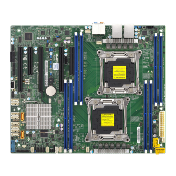
Page 12: Motherboard Layout
HD AUDIO JHD_AC1 LAN2 LAN1 X10DAL-i FAN5 Rev. 1.02 CPU2 BIOS Battery S-SATA3 S-SATA2 S-SATA1 S-SATA0 CPU1 JSD2 I-SATA3 I-SATA2 I-SATA1 I-SATA0 JPWR2 JSTBY1 LEDPWR JPWR1 Note: For the latest CPU/Memory updates, please refer to our website at http://www.supermicro.com/products/motherboard/ for details. -
Page 13: X10Dal-I Quick Reference
X10DAL-i Motherboard User's Manual X10DAL-i Quick Reference USB5/6 (3.0) USB3/4 (3.0) FAN6 JPI2C1 JPL2 HD AUDIO JHD_AC1 LAN2 LAN1 X10DAL-i FAN5 Rev. 1.02 CPU2 BIOS Battery S-SATA3 S-SATA2 S-SATA1 S-SATA0 CPU1 JSD2 I-SATA3 I-SATA2 I-SATA1 I-SATA0 JPWR2 JSTBY1 LEDPWR JPWR1 Notes: •... -
Page 14: Default Setting
Chapter 1: Overview X10DAL-i Jumpers Jumper Description Default Setting JBT1 Clear CMOS See Chapter 2 C1/JI SMBus to PCI-E slots Pins 2-3 (Disabled) JPAC1 Audio enable Pins 1-2 (Enabled) JPL1 GLAN1 Enable/Disable Pins 1-2 (Enabled) JPL2 GLAN2 Enable/Disable Pins 1-2 (Enabled) - Page 15 LAN1/LAN2 Gigabit Ethernet ports 1/2 I-SATA0-5 Serial_Link ATA (SATA 3.0) connections 0-5 supported by Intel PCH (I-SATA4/5 support Supermicro SuperDOMs [Devices-on-Module] with power pins built-in) S-SATA 0-3 Serial_Link ATA (SATA 3.0) connections 0-3 supported by Intel SCU Onboard buzzer (internal speaker)
-
Page 16: Motherboard Features
• • SATA Ports Six (6) SATA 3.0 ports sup- ported by Intel PCH (I-SATA 0-5) Note: I-SATA4/5 sup- port Supermicro Su- perDOMs [Devices- on-Module] with power pins built-in) • Four (4) SATA 3.0 ports supported by Intel SCU (S-SATA 0-3) •... - Page 17 X10DAL-i Motherboard User's Manual Peripheral USB Devices Devices • Four (4) USB 3.0 connections on the IO backpanel (USB 3/4, 5/6) • Two (2) USB 3.0 connections for front access (USB 7/8) • Two (2) USB 2.0 connections for front access (USB 1/2) •...
- Page 18 Chapter 1: Overview System- CPU Monitoring Health • Monitoring Onboard voltage monitors for 1.05V, 1.25V, 1.5V, +3.3V, 3.3VSB, +5V, +5V Standby, +12V, chipset, memory, CPU1/2 vcores, and battery voltages. • CPU/System overheat LED and control • CPU Thermal Trip support •...
-
Page 19: System Block Diagram
X10DAL-i Motherboard User's Manual Block Diagram Rev. 1.02 X10DAL-i VR12.5 VR12.5 #2-4 #1-4 5 PHASE 5 PHASE #2-3 #1-3 160W 160W #2-2 #1-2 #2-1 #1-1 9.6G CPU1 CPU2 SNB CORE SNB CORE DDR4 DDR4 9.6G #1 DMI #1 #2A PCI-E x16 G3... -
Page 20: Processor And Chipset Overview
Processor and Chipset Overview Built upon the functionality and the capability of the Intel E5-2600v3 Series proces- sors (Socket R v3 LGA 2011) and the C612 chipset, the X10DAL-i motherboard provides the performance and feature sets required for small-form factor worksta- tion platforms, optimized for medical imaging applications. -
Page 21: Special Features
X10DAL-i Motherboard User's Manual Special Features Recovery from AC Power Loss The Basic I/O System (BIOS) provides a setting that determines how the system will respond when AC power is lost and then restored to the system. You can choose for the system to remain powered off (in which case you must press the power switch to turn it back on), or for it to automatically return to the power-on state. -
Page 22: Acpi Features
It is even more important for processors that have high CPU clock rates. The X10DAL-i motherboard accommodates 24-pin ATX power supplies. Although most power supplies generally meet the specifications required by the CPU, some are inadequate. In addition, two 8-pin power connections are also required to en- sure adequate power supply to the system. -
Page 23: Super I/O
X10DAL-i Motherboard User's Manual Super I/O The Super I/O supports one high-speed, 16550 compatible serial communication port (UART). The UART includes a 16-byte send/receive FIFO, a programmable baud rate generator, complete modem control capability, and a processor interrupt system. The UART provides legacy speed with a baud rate of up to 115.2 Kbps as well as an advanced speed with baud rates of 250 K, 500 K, or 1 Mb/s, which support higher speed modems. -
Page 24: Chapter 2 Installation
The following statements are industry-standard warnings, provided to warn the user of situations where bodily injuries may occur. Should you have questions, contact Supermicro's Technical Support for assistance. Only certified technicians should attempt to install or change components. Read this section in its entirety before installing or removing components in the Supermicro chassis. - Page 25 X10DAL-i Motherboard User's Manual Attention Danger d'explosion si la pile n'est pas remplacée correctement. Ne la remplacer que par une pile de type semblable ou équivalent, recommandée par le fabricant. Jeter les piles usagées conformément aux instructions du fabricant. ¡Advertencia! Existe peligro de explosión si la batería se reemplaza de manera incorrecta.
-
Page 26: Product Disposal
Chapter 2: Installation Product Disposal Warning! Ultimate disposal of this product should be handled according to all national laws and regulations. 製品の廃棄 この製品を廃棄処分する場合、 国の関係する全ての法律 ・ 条例に従い処理する必要が あります。 警告 本产品的废弃处理应根据所有国家的法律和规章进行。 警告 本產品的廢棄處理應根據所有國家的法律和規章進行。 Warnung Die Entsorgung dieses Produkts sollte gemäß allen Bestimmungen und Gesetzen des Landes erfolgen. -
Page 27: Static-Sensitive Devices
X10DAL-i Motherboard User's Manual 경고! 이 제품은 해당 국가의 관련 법규 및 규정에 따라 폐기되어야 합니다. Waarschuwing De uiteindelijke verwijdering van dit product dient te geschieden in overeenstemming met alle nationale wetten en reglementen. Static-Sensitive Devices Electrostatic Discharge (ESD) can damage electronic com ponents. To avoid dam- aging your system board, it is important to handle it very carefully. -
Page 28: Motherboard Installation
Location of Mounting Holes There are eight (8) mounting holes on this motherboard indicated by the arrows. USB5/6 (3.0) USB3/4 (3.0) FAN6 JPI2C1 JPL2 HD AUDIO JHD_AC1 LAN2 LAN1 X10DAL-i FAN5 Rev. 1.02 CPU2 BIOS Battery S-SATA3 S-SATA2 S-SATA1 S-SATA0 CPU1 JSD2 I-SATA3... -
Page 29: Installing The Motherboard
X10DAL-i Motherboard User's Manual Installing the Motherboard Note: Always connect the power cord last, and always remove it before adding, removing or changing any hardware components. 1. Install the I/O shield into the chassis. 2. Locate the mounting holes on the motherboard. -
Page 30: Processor And Heatsink Installation
CPU socket cap is in place and none of the socket pins are bent; otherwise, contact your retailer immediately. • Refer to the Supermicro website for updates on CPU support. Installing the LGA2011 Processor 1. There are two load levers on the LGA2011 socket. To open the socket cover, first press and release the load lever labeled "Open 1st."... - Page 31 X10DAL-i Motherboard User's Manual 2. Press the second load lever labeled "Close 1st" to release the load plate that covers the CPU socket from its locking position. Pull lever away from Press down on load socket lever "Close 1st" 3. With the lever labeled "Close 1st" fully retracted, gently push down on the lever labeled "Open 1st"...
- Page 32 Chapter 2: Installation 4. Use your thumb and index finger to loosen the lever and open the load plate. 5. Using your thumb and index finger, hold the CPU by its edges. Align the CPU keys, which are semicircle notches, against the socket keys. Socket Keys CPU Keys 6.
- Page 33 X10DAL-i Motherboard User's Manual 7. With the CPU inside the socket, inspect the four corners of the CPU to make sure that the CPU is properly installed. Gently close Push down and lock the the load plate lever labeled "Close 1st"...
-
Page 34: Installing A Passive Cpu Heatsink
Chapter 2: Installation Installing a Passive CPU Heatsink 1. Do not apply any thermal grease to the heatsink or the CPU die -- the re- quired amount has already been applied. 2. Place the heatsink on top of the CPU so that the four mounting holes are aligned with those on the motherboard and the heatsink bracket underneath. -
Page 35: Removing The Heatsink
X10DAL-i Motherboard User's Manual Removing the Heatsink Warning: We do not recommend that the CPU or the heatsink be removed. However, if you do need to uninstall the heatsink, please follow the instructions below to uninstall the heatsink to prevent damage done to the CPU or the CPU socket. -
Page 36: Installing And Removing The Memory Modules
Chapter 2: Installation Installing and Removing the Memory Modules Note: Check Supermicro's website for recommended memory modules. CAUTION Exercise extreme care when installing or removing DIMM modules to prevent any possible damage. Installing & Removing DIMMs 1. Insert the desired number of DIMMs into the memory slots, starting with P1-DIMMA1. -
Page 37: Memory Support
Note1: Memory speed support is dependent on the CPUs installed on the motherboard. Note2: For the latest memory updates, please refer to the Tested Memory List posted on our website (http://www.supermicro.com/products/mother- board). Processor & Memory Module Population Configuration For memory to work properly, follow the tables below for memory population. - Page 38 Chapter 2: Installation Populating RDIMM/LRDIMM ECC Memory Modules 2-15...
-
Page 39: Control Panel Connectors And I/O Ports
X10DAL-i Motherboard User's Manual Control Panel Connectors and I/O Ports The I/O ports are color coded in conformance with the industry standards. See the picture below for the colors and locations of the various I/O ports. Backpanel Connectors and I/O Ports USB5/6 (3.0) -
Page 40: Ethernet Ports
Ground TD3- Ground (NC: No Connection) 1. LAN1 USB5/6 (3.0) USB3/4 (3.0) FAN6 JPI2C1 2. LAN2 JPL2 HD AUDIO JHD_AC1 LAN2 LAN1 X10DAL-i FAN5 Rev. 1.02 CPU2 BIOS Battery S-SATA3 S-SATA2 S-SATA1 S-SATA0 CPU1 JSD2 I-SATA3 I-SATA2 I-SATA1 I-SATA0 JPWR2... -
Page 41: Universal Serial Bus (Usb)
X10DAL-i Motherboard User's Manual Universal Serial Bus (USB) Six Universal Serial Bus (USB) 3.0 ports and three USB 2.0 connections are located on the motherboard. USB 3.0 ports 3/4 and 5/6 are located on the IO backpanel, while the USB 3.0 header that provides two USB 3.0 connections (USB 7/8) is located next to the Front Control panel. -
Page 42: 5.1 Hd (High-Definition) Audio
3. CEN/LFE_Out Headphone_Detect 4. Mic_In USB5/6 (3.0) USB3/4 (3.0) 5. Line-Out FAN6 JPI2C1 JPL2 6. Line_In HD AUDIO JHD_AC1 LAN2 LAN1 X10DAL-i FAN5 Rev. 1.02 7. Audio Header CPU2 BIOS Battery S-SATA3 S-SATA2 S-SATA1 S-SATA0 CPU1 JSD2 I-SATA3 I-SATA2 I-SATA1... -
Page 43: Front Control Panel
These connectors are designed specifically for use with Supermicro's server chassis. See the figure below for the descriptions of the various control panel buttons and LED indicators. Refer to the following section for descriptions and pin definitions. -
Page 44: Front Control Panel Pin Definitions
PWR LED A. NMI B. PWR LED USB5/6 (3.0) USB3/4 (3.0) FAN6 JPI2C1 JPL2 HD AUDIO JHD_AC1 LAN2 LAN1 X10DAL-i Ground FAN5 Rev. 1.02 Power LED CPU2 BIOS HDD LED Battery NIC1 LED S-SATA3 NIC2 LED S-SATA2 S-SATA1 S-SATA0... -
Page 45: Hdd Led
X10DAL-i Motherboard User's Manual HDD LED HDD LED Pin Definitions (JF1) The HDD LED connection is located Pin # Definition on pins 13 and 14 of JF1. Attach a 3.3V Standby cable here to indicate HDD activ- HD Active ity. See the table on the right for pin definitions. -
Page 46: Overheat (Oh)/Fan Fail Led
PWR Supply Fail A. OH/Fail Fail LED B. PWR Supply Fail USB5/6 (3.0) USB3/4 (3.0) FAN6 JPI2C1 JPL2 HD AUDIO JHD_AC1 LAN2 LAN1 X10DAL-i Ground FAN5 Rev. 1.02 Power LED CPU2 BIOS HDD LED Battery NIC1 LED S-SATA3 NIC2 LED S-SATA2 S-SATA1... -
Page 47: Reset Button
X10DAL-i Motherboard User's Manual Reset Button Reset Button Pin Definitions (JF1) The Reset Button connection is located Pin # Definition on pins 3 and 4 of JF1. Attach it to a Reset hardware reset switch on the computer Ground case. Refer to the table on the right for pin definitions. -
Page 48: Connecting Cables
A. J24: 24-pin ATX PWR USB5/6 (3.0) USB3/4 (3.0) FAN6 JPI2C1 (Req'd) JPL2 HD AUDIO JHD_AC1 LAN2 LAN1 B. JPWR1: 8-pin Proces- X10DAL-i FAN5 Rev. 1.02 sor PWR (Req'd) C. JPWR2: 8-pin Proces- sor PWR (Req'd) CPU2 BIOS Battery S-SATA3 S-SATA2 S-SATA1 S-SATA0 CPU1... -
Page 49: Fan Headers
X10DAL-i Motherboard User's Manual Fan Headers Fan Header Pin Definitions This motherboard has seven system/CPU Pin # Definition fan headers (Fan 1~Fan 6, and Fan A) Ground on the motherboard. All these 4-pin fans +12V headers are backward-compatible with Tachometer the traditional 3-pin fans. -
Page 50: Internal Speaker
See the tables on the right for pin definitions. USB5/6 (3.0) USB3/4 (3.0) A. Internal Speaker FAN6 JPI2C1 (Buzzer) JPL2 HD AUDIO JHD_AC1 LAN2 LAN1 X10DAL-i B. PWR LED/Speaker FAN5 Rev. 1.02 CPU2 BIOS Battery S-SATA3 S-SATA2 S-SATA1 S-SATA0 CPU1 JSD2 I-SATA3 I-SATA2... -
Page 51: Tpm Header/Port 80 Header
X10DAL-i Motherboard User's Manual TPM Header/Port 80 Header TPM/Port 80 Header Pin Definitions A Trusted Platform Module/Port 80 Pin # Definition Pin # Definition header is located at JTPM1 to provide LCLK TPM support and Port 80 connection. LFRAME# <(KEY)>... -
Page 52: I-Sgpio 1/2 & S-Sgpio Headers
A. I-SGPIO1 USB5/6 (3.0) USB3/4 (3.0) FAN6 JPI2C1 B. I-SGPIO2 JPL2 HD AUDIO JHD_AC1 LAN2 LAN1 C. S-SGPIO X10DAL-i FAN5 Rev. 1.02 D. JSD1 E. JSD2 CPU2 BIOS Battery S-SATA3 S-SATA2 S-SATA1 S-SATA0 CPU1 JSD2 I-SATA3 I-SATA2... -
Page 53: Spdif_In/Spdif_Out Headers
X10DAL-i Motherboard User's Manual SPDIF_In/SPDIF_Out Headers SPDIF_In SPDIF_Out Pin Definitions Pin Definitions The SPDIF_In (JSPDIF_In) and SP- Pin # Definition Pin # Definition DIF_Out (JSPDIF_Out) headers are S/PDIF_In S/PDIF_Out located next to the GLAN Controller Ground Ground on the motherboard. Place a cap on each header for audio support. -
Page 54: Com Header
This header provides serial-port (COM) connection support. Refer to the board layout below for the location. A. COM1 USB5/6 (3.0) USB3/4 (3.0) FAN6 JPI2C1 JPL2 HD AUDIO JHD_AC1 LAN2 LAN1 X10DAL-i FAN5 Rev. 1.02 CPU2 BIOS Battery S-SATA3 S-SATA2 S-SATA1 S-SATA0 CPU1 JSD2 I-SATA3 I-SATA2... -
Page 55: Jumper Settings
X10DAL-i Motherboard User's Manual Jumper Settings Explanation of Jumpers Connector Pins To modify the operation of the mother- board, jumpers can be used to choose between optional settings. Jumpers Jumper create shorts between two pins to change the function of the connector. -
Page 56: Cmos Clear
Dog must also be enabled in the BIOS. A. Clear CMOS USB5/6 (3.0) USB3/4 (3.0) FAN6 JPI2C1 B. Watch Dog Enable JPL2 HD AUDIO JHD_AC1 LAN2 LAN1 X10DAL-i FAN5 Rev. 1.02 CPU2 BIOS Battery S-SATA3 S-SATA2 S-SATA1 S-SATA0 CPU1 JSD2 I-SATA3 I-SATA2... -
Page 57: I 2 C Bus To Pci-Exp. Slots
X10DAL-i Motherboard User's Manual C Bus to PCI-Exp. Slots C for PCI-E slots Jumper Settings Use Jumpers JI C1 and JI C2 to con- Jumper Setting Definition nect the System Management Bus (I Pins 1-2 Enabled to PCI-Express slots to improve PCI... -
Page 58: Onboard Audio Enable
See the table on the right for jumper settings. USB5/6 (3.0) USB3/4 (3.0) A. Onboard Audio Enable FAN6 JPI2C1 JPL2 HD AUDIO JHD_AC1 LAN2 LAN1 X10DAL-i FAN5 Rev. 1.02 CPU2 BIOS Battery S-SATA3 S-SATA2 S-SATA1 S-SATA0 CPU1 JSD2 I-SATA3 I-SATA2... -
Page 59: Usb 0/1 Wake-Up Enable
X10DAL-i Motherboard User's Manual USB 0/1 Wake-up Enable USB 0/1 Wake-up Enable Jumper Settings Jumper JPUSB1 is used for USB 0/1 Jumper Setting Definition wake-up support, which will allow the Pins 1-2 Enabled (Default) system to "wake-up" when a signal sent... -
Page 60: Onboard Led Indicators
See the table on the right for more information. USB5/6 (3.0) USB3/4 (3.0) A. LAN1/2 LEDs FAN6 JPI2C1 JPL2 B. Onboard PWR HD AUDIO JHD_AC1 LAN2 LAN1 X10DAL-i FAN5 Rev. 1.02 CPU2 BIOS Battery S-SATA3 S-SATA2 S-SATA1 S-SATA0 CPU1 JSD2 I-SATA3 I-SATA2 I-SATA1... -
Page 61: 2-10 Sata 3.0 Connections
Intel PCH, and S-SATA0-3 are sup- TX_P ported by the Intel SCU. I-SATA4/5 can be used TX_N with Supermicro SuperDOMs which are yellow SATA Ground DOM connectors with power pins built in, and no ex- ternal cables are required. Supermicro SuperDOMs... -
Page 62: Chapter 3 Troubleshooting
Chapter 3: Troubleshooting Chapter 3 Troubleshooting Troubleshooting Procedures Use the following procedures to troubleshoot your system. If you have followed all of the procedures below and still need assistance, refer to the ‘Technical Support Procedures’ and/or ‘Returning Merchandise for Service’ section(s) in this chapter. Note: Always disconnect the power cord before adding, changing or installing any hardware components. -
Page 63: No Video
X10DAL-i Motherboard User's Manual No Video 1. If the power is on, but you have no video, remove all the add-on cards and cables. 2. Use the speaker to determine if any beep codes exist. Refer to Appendix A for details on beep codes. -
Page 64: Memory Errors
2. Memory support: Make sure that the memory modules are supported by test- ing the modules using memtest86 or a similar utility. Note: Refer to the product page on our website http://www.supermicro. com for memory and CPU support and updates. - Page 65 X10DAL-i Motherboard User's Manual within the normal range. Also check the front panel Overheat LED, and make sure that the Overheat LED is not on. 5. Adequate power supply: Make sure that the power supply provides adequate power to the system. Make sure that all power connectors are connected.
-
Page 66: Technical Support Procedures
Technical Support Procedures Before contacting Technical Support, please take the following steps. Also, please note that as a motherboard manufacturer, Supermicro also sells motherboards through its channels, so it is best to first check with your distributor or reseller for troubleshooting services. -
Page 67: Battery Removal And Installation
X10DAL-i Motherboard User's Manual Battery Removal and Installation Battery Removal To remove the onboard battery, follow the steps below: 1. Power off your system and unplug your power cable. 2. Locate the onboard battery as shown below. 3. Using a tool such as a pen or a small screwdriver, push the battery lock out- wards to unlock it. -
Page 68: Frequently Asked Questions
Note: The SPI BIOS chip used on this motherboard cannot be removed. Send your motherboard back to our RMA Department at Supermicro for repair. For BIOS Recovery instructions, please refer to the AMI BIOS Recovery Instructions posted at http://www.supermicro.com. -
Page 69: Returning Merchandise For Service
X10DAL-i Motherboard User's Manual Returning Merchandise for Service A receipt or copy of your invoice marked with the date of purchase is required before any warranty service will be rendered. You can obtain service by calling your ven- dor for a Returned Merchandise Authorization (RMA) number. When returning the... -
Page 70: Chapter 4 Bios
Appendix A: BIOS POST Error Codes Appendix A BIOS POST Error Beep Codes During the POST (Power-On Self-Test) routines, which are performed at each system boot, errors may occur. Non-fatal errors are those which, in most cases, allow the system to continue to boot. - Page 71 X10DAL-i Motherboard User’s Manual Notes...
-
Page 72: Appendix B Software Installation Instructions
To install these programs, click the icons to the right of these items. Note: To install the Windows OS, please refer to the instructions posted on our Website at http://www.supermicro.com/support/manuals/. Driver/Tool Installation Display Screen Note 1: Click the icons showing a hand writing on the paper to view the readme files for each item. -
Page 73: Configuring Superdoctor® 5
X10DAL-i Motherboard User's Manual B-2 Configuring SuperDoctor® 5 The Supermicro SuperDoctor 5 is a hardware monitoring program that functions in a command-line or web-based interface in Windows and Linux operating systems. The program monitors system health information such as CPU temperature, system voltages, system power consumption, fan speed, and provides alerts via email or Simple Network Management Protocol (SNMP). -
Page 74: C-1 An Overview To The Uefi Bios
Flashing the wrong BIOS can cause irreparable damage to the system. In no event shall Supermicro be liable for direct, indirect, special, incidental, or consequential damages arising from a BIOS update. If you need to update the BIOS, do not shut down or reset the system while the BIOS is updating to avoid possible boot failure. - Page 75 Root "\" Directory of a USB device or a writeable CD/DVD. Note: If you cannot locate the "Super.ROM" file in your driver disk, visit our website at www.supermicro.com to download the BIOS image into a USB flash device and rename it "Super.ROM" for BIOS recovery use.
- Page 76 Appendix C: UEFI BIOS Recovery 5. When the screen as shown above displays, using the arrow key, select the item "Proceed with flash update" and press the <Enter> key. You will see the progress of BIOS recovery as shown in the screen below. Note: Do not interrupt the process of BIOS flashing until it is completed.
- Page 77 X10DAL-i Motherboard User’s Manual 7. Using a different system, extract the BIOS package into a bootable USB flash drive. 8. When a DOS prompt appears, enter FLASH.BAT BIOSname.### at the prompt. Note: Do not interrupt this process until BIOS flashing is completed.
- Page 78 (Disclaimer Continued) The products sold by Supermicro are not intended for and will not be used in life support systems, medical equipment, nuclear facilities or systems, aircraft, aircraft devices, aircraft/emergency com- munication devices or other critical systems whose failure to perform be reasonably expected to result in significant injury or loss of life or catastrophic property damage.
Need help?
Do you have a question about the X10DAL-i and is the answer not in the manual?
Questions and answers