Table of Contents
Advertisement
Quick Links
Advertisement
Table of Contents

Related Manuals for Supermicro X10DDW-i


Summary of Contents for Supermicro X10DDW-i
- Page 1 X10DDW-i X10DDW-iN USER’S MANUAL Revision 1.0b...
- Page 2 This product, including software and docu- mentation, is the property of Supermicro and/or its licensors, and is supplied only under a license. Any use or reproduction of this product is not allowed, except as expressly permitted by the terms of said license.
- Page 3 Preface Preface This manual is written for system integrators, PC technicians and IT professionals. It provides information for the installation and use of the X10DDW-i/ iN motherboard. About This Motherboard The Super X10DDW-i/iN motherboard supports dual Intel E5-2600v3/v4 processors (Socket R3) that offer the new Intel Microarchitecture 22nm (E5-2600v3)/14nm (E5-...
- Page 4 X10DDW-i/iN Motherboard User’s Manual Conventions Used in the Manual Pay special attention to the following symbols for proper system installation: Warning: Important information given to ensure proper system installation or to prevent damage to the components or injury to yourself;...
- Page 5 Super Micro Computer, Inc. 980 Rock Ave. San Jose, CA 95131 U.S.A. Tel: +1 (408) 503-8000 Fax: +1 (408) 503-8008 Email: marketing@supermicro.com (General Information) support@supermicro.com (Technical Support) Website: www.supermicro.com Europe Address: Super Micro Computer B.V. Het Sterrenbeeld 28, 5215 ML...
-
Page 6: Table Of Contents
ACPI Features ....................1-13 Power Supply ....................1-13 Advanced Power Management ..............1-14 Intel Intelligent Power Node Manager (NM) (Available when the Supermicro ® Power Manager [SPM] is Installed) .............. 1-14 Management Engine (ME) ................1-14 Introduction to the AOM-S3108M-H8 Rev. 2.00 Mezzanine Card ....1-14 Chapter 2 Installation Standardized Warning Statements .............. - Page 7 Table of Contents HDD/UID LED ..................2-25 NIC1/NIC2 LED Indicators ............... 2-25 Overheat (OH)/Fan Fail/PWR Fail/UID LED ..........2-26 Power Fail LED ..................2-26 Reset Button ................... 2-27 Power Button ................... 2-27 Connecting Cables ..................2-28 Power Connectors ................... 2-28 Fan Headers .....................
- Page 8 X10DDW-i/iN Motherboard User’s Manual Battery Removal and Installation ..............3-6 Frequently Asked Questions ................3-7 Returning Merchandise for Service..............3-8 Chapter 4 BIOS Introduction ...................... 4-1 Main Setup ...................... 4-2 Advanced Setup Configurations..............4-4 Event Logs ....................4-31 IPMI ....................... 4-33 Security Settings ...................
-
Page 9: Chapter 1 Overview
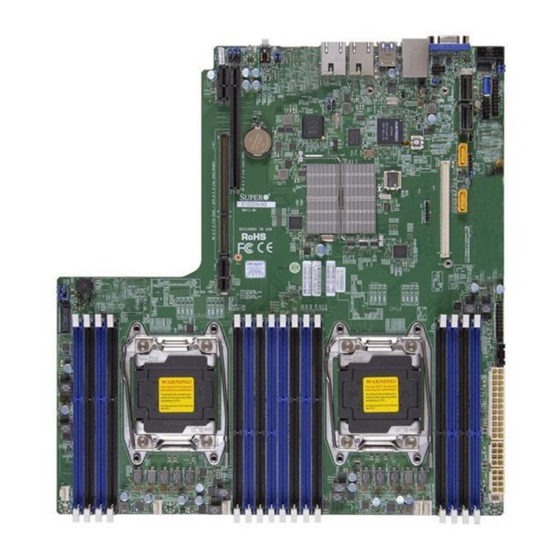
Checklist Congratulations on purchasing your computer motherboard from an acknowledged leader in the industry. Supermicro boards are designed with the utmost attention to detail to provide you with the highest standards in quality and performance. Please check that the following items have all been included with your motherboard. - Page 10 X10DDW-i/iN Motherboard User’s Manual Motherboard Image Note: All graphics shown in this manual were based upon the latest PCB Revision available at the time of publishing of the manual. The motherboard you've received may or may not look exactly the same as the graphics...
- Page 11 JOH1 IPMI_LAN JWD1 JSXB1_2 BIOS JBT1 BIOS LICENSE X10DDW-i P1_NVME0 P1_NVME1 Rev. 1.10 CLOSE 1st CLOSE 1st CPU1 CPU2 OPEN 1st OPEN 1st FAN8 FAN6 Note: For the latest CPU/Memory updates, please refer to our website at http://www.supermicro.com/products/motherboard/ for details.
- Page 12 X10DDW-i/iN Motherboard User’s Manual X10DDW-i/iN Quick Reference USB0/1(2.0) LAN2 LAN1 USB4/5(3.0) COM1 I-SGPIO2 JSTBY1 JOH1 IPMI_LAN JWD1 JSXB1_2 BIOS JBT1 BIOS LICENSE X10DDW-i P1_NVME0 P1_NVME1 Rev. 1.10 CLOSE 1st CLOSE 1st CPU1 CPU2 OPEN 1st OPEN 1st FAN8 FAN6 Notes: •...
- Page 13 Chapter 1: Overview X10DDW-i/iN Jumpers Jumper Description Default Setting JBT1 Clear CMOS See Chapter 2 C1/JI C2 SMB to PCI-E Slots Pins 2-3 (Disabled) JPB1 BMC Enable Pins 1-2 (Enabled) JPG1 VGA Enable Pins 1-2 (Enabled) JPLAN1 GLAN1/GLAN2 Enable Pins 1-2 (Enabled)
- Page 14 X10DDW-i/iN Motherboard User’s Manual SXB1B SMCI-proprietary CPU1 PCI-E 3.0 x16 + CPU2 PCI-E (JSXB1_1/1_2/1_3) 3.0 x16 slot w/riser-card support SXB2 CPU1 PCI-E 3.0 x8 slot for low-profile (LP) riser-card support UID (JUIDB1) Unit Identified (UID) button (BP) USB 0/1 Backpanel USB 2.0 Ports 0/1 (FP) USB 2/3 Front accessible USB 2.0 connection header 2/3...
- Page 15 2400/2133/1866/1600 MHz memory in 16 slots (2 DIMMs per channel). Note: Memory speed support is pending on the processors installed in the system. For the lat- est CPU/memory updates, please refer to our website at http://www.supermicro.com/products/ motherboard. DIMM sizes • DIMM Up to 128GB @ 1.2V...
- Page 16 Power-on mode for AC power recovery • Intel Intelligent Power Node Manager 3.0 (Available ® when the Supermicro Power Manager [SPM] is in- stalled and special power supply used. See the note on Page 1-14.) • Management Engine (ME) System...
- Page 17 Refer to the block diagram on page 1-10 to determine which slots or devices may be affected. Please populate CPU socket 1 first. Note 3: For IPMI Configuration Instructions, please refer to the Embedded IPMI Configuration User's Guide available @ http://www.supermicro.com/ support/manuals/.
- Page 18 X10DDW-i/iN Motherboard User’s Manual #1-8 #2-8 #1-7 #2-7 VR12.5 VR12.5 #1-6 #2-6 #1-5 5 PHASE 5 PHASE #2-5 145W 145W #1-4 #2-4 #1-3 #2-3 #1-2 Processor 2 Processor 1 #2-2 #1-1 #2-1 9.6G DDR4 DDR4 9.6G DMI2 #1 #3B DMI2...
-
Page 19: Processor And Chipset Overview
Processor and Chipset Overview Built upon the functionality and capability of the Intel E5-2600v3/v4 processors (Socket R3) and the Intel C612 PCH, the X10DDW-i/iN motherboard provides the best balanced solution of performance, power efficiency, and features to address the diverse needs of next-generation data centers. -
Page 20: Special Features
X10DDW-i/iN Motherboard User’s Manual Special Features Recovery from AC Power Loss The Basic I/O System (BIOS) provides a setting that determines how the system will respond when AC power is lost and then restored to the system. You can choose for the system to remain powered off (in which case you must press the power switch to turn it back on), or for it to automatically return to the power-on state. -
Page 21: Acpi Features
It is even more important for processors that have high CPU clock rates. The X10DDW-i/iN motherboard accommodates 24-pin ATX power supplies. Al- though most power supplies generally meet the specifications required by the CPU, some are inadequate. In addition, two 12V 8-pin power connections are also required to ensure adequate power supply to the system. -
Page 22: Advanced Power Management
Introduction to the AOM-S3108M-H8 Rev. 2.00 Mezzanine Card The Supermicro AOM-S3108M-H8 Rev. 2.00 is a highly-efficient SAS controller mezzanine card that offers a high level of performance in today’s server and stor- age environments. This mezzanine card can directly support eight SSD devices and delivers SAS data transfer rates of up to 12Gb/s. -
Page 23: Chapter 2 Installation
The following statements are industry-standard warnings, provided to warn the user of situations which have the potential for bodily injury. Should you have questions or experience difficulty, contact Supermicro's Technical Support department for assis- tance. Only certified technicians should attempt to install or configure components. - Page 24 X10DDW-i/iN Motherboard User’s Manual Attention Danger d'explosion si la pile n'est pas remplacée correctement. Ne la remplacer que par une pile de type semblable ou équivalent, recommandée par le fabricant. Jeter les piles usagées conformément aux instructions du fabricant. ¡Advertencia! Existe peligro de explosión si la batería se reemplaza de manera incorrecta.
- Page 25 Chapter 2: Installation Product Disposal Warning! Ultimate disposal of this product should be handled according to all national laws and regulations. 製品の廃棄 この製品を廃棄処分する場合、 国の関係する全ての法律 ・ 条例に従い処理する必要が あります。 警告 本产品的废弃处理应根据所有国家的法律和规章进行。 警告 本產品的廢棄處理應根據所有國家的法律和規章進行。 Warnung Die Entsorgung dieses Produkts sollte gemäß allen Bestimmungen und Gesetzen des Landes erfolgen.
-
Page 26: Static-Sensitive Devices
X10DDW-i/iN Motherboard User’s Manual 경고! 이 제품은 해당 국가의 관련 법규 및 규정에 따라 폐기되어야 합니다. Waarschuwing De uiteindelijke verwijdering van dit product dient te geschieden in overeenstemming met alle nationale wetten en reglementen. Static-Sensitive Devices Electrostatic Discharge (ESD) can damage electronic com ponents. To avoid dam- aging your system board, it is important to handle it very carefully. -
Page 27: Motherboard Installation
USB4/5(3.0) COM1 I-SGPIO2 JSTBY1 JOH1 IPMI_LAN JWD1 JSXB1_2 BIOS JBT1 BIOS LICENSE X10DDW-i P1_NVME0 P1_NVME1 Rev. 1.10 CLOSE 1st CLOSE 1st CPU1 CPU2 OPEN 1st OPEN 1st FAN8 FAN6 Caution: 1) To avoid damaging the motherboard and its components, please do not use a force greater than 8 lb/inch on each mounting screw during motherboard installation. - Page 28 X10DDW-i/iN Motherboard User’s Manual Installing the Motherboard Note: Always connect the power cord last, and always remove it before adding, removing or changing any hardware components. Install the I/O shield into the chassis. 1. Locate the mounting holes on the motherboard.
-
Page 29: Processor And Heatsink Installation
CPU socket cap is in place and none of the socket pins are bent; otherwise, contact your retailer immediately. Refer to the Supermicro website for updates on CPU support. Installing the LGA2011 Processor 1. There are two load levers on the LGA2011 socket. To open the socket cover, first press and release the load lever labeled 'Open 1st'. - Page 30 X10DDW-i/iN Motherboard User’s Manual 2. Press the second load lever labeled 'Close 1st' to release the load plate that covers the CPU socket from its locking position. Pull lever away from Press down on Load the socket Lever 'Close 1st' 3.
- Page 31 Chapter 2: Installation 4. Use your thumb and the index finger to loosen the lever and open the load plate. 5. Using your thumb and index finger, hold the CPU on its edges. Align the CPU keys, which are semi-circle cutouts, against the socket keys. Socket Keys CPU Keys 6.
- Page 32 X10DDW-i/iN Motherboard User’s Manual 7. With the CPU inside the socket, inspect the four corners of the CPU to make sure that the CPU is properly installed. Gently close Push down and lock the the load plate. lever labeled 'Close 1st'.
-
Page 33: Installing A Passive Cpu Heatsink
Chapter 2: Installation Installing a Passive CPU Heatsink 1. Do not apply any thermal grease to the heatsink or the CPU die -- the re- quired amount has already been applied. 2. Place the heatsink on top of the CPU so that the four mounting holes are aligned with those on the Motherboard and the Heatsink Bracket underneath. -
Page 34: Removing The Heatsink
X10DDW-i/iN Motherboard User’s Manual Removing the Heatsink Warning: We do not recommend that the CPU or the heatsink be removed. However, if you do need to uninstall the heatsink, please follow the instructions below to uninstall the heatsink to prevent damage done to the CPU or the CPU socket. -
Page 35: Installing And Removing The Memory Modules
Chapter 2: Installation Installing and Removing the Memory Modules Note: Check Supermicro's website for recommended memory modules. CAUTION Exercise extreme care when installing or removing DIMM modules to prevent any possible damage. Installing & Removing DIMMs 1. Insert the desired number of DIMMs into the memory slots, starting with P1-DIMM A1. - Page 36 X10DDW-i/iN Motherboard User’s Manual Memory Support for the X10DDW-i/iN Motherboard The X10DDW-i/iN Motherboard supports up to 2048 GB of Load Reduction (LRDIMM), and up to 512 GB of Registered (RDIMM) DDR4 (288-pin) ECC 2400/2133/1866/1600 MHz memory in 16 slots (2 DIMMs per channel).
- Page 37 Chapter 2: Installation Populating RDIMM/LRDIMM DDR4 Memory Modules for the E5- 2600v4-based Motherboard Speed (MT/s); Voltage (V); Slot Per Channel (SPC) and DIMM Per Channel (DPC) DIMM Capacity Ranks Per 1 Slot Per (GB) DIMM and 2 Slots Per Channel Type Channel Data...
-
Page 38: Mezzanine Card Installation
X10DDW-i/iN Motherboard User’s Manual Mezzanine Card Installation For SAS 3.0 support, be sure to follow the instructions below to install the AOM- S3108M-H8 Rev. 2.00 Mezzanine card on the AOM PCI-E 3.0 slot located at Slot JMEZ1. Image of the Mezzanine Card 1. - Page 39 Chapter 2: Installation 3. With the mezzanine card securely placed in the slot, insert Pan Head #6 screws into the three standoff holes and tighten them with a Phillips screw- driver. Screw #2 Screw #1 Screw #3 2-17...
-
Page 40: Control Panel Connectors And I/O Ports
X10DDW-i/iN Motherboard User’s Manual Control Panel Connectors and I/O Ports The I/O ports are color coded in conformance with the industry standards. See the picture below for the colors and locations of the various I/O ports. Back Panel Connectors and I/O Ports USB0/1(2.0) -
Page 41: Com Header
Refer to the board layout below for the location. 1. COM1 2. VGA LAN2 LAN1 USB4/5(3.0) USB0/1(2.0) COM1 I-SGPIO2 JSTBY1 JOH1 IPMI_LAN JWD1 JSXB1_2 BIOS JBT1 BIOS LICENSE X10DDW-i P1_NVME0 P1_NVME1 Rev. 1.10 CLOSE 1st CLOSE 1st CPU1 CPU2 OPEN 1st OPEN 1st FAN8 FAN6 2-19... -
Page 42: Universal Serial Bus (Usb)
X10DDW-i/iN Motherboard User’s Manual Universal Serial Bus (USB) Two USB 2.0 ports (USB 0/1) and two USB 3.0 ports (USB 4/5) are located on the I/O back panel. In addition, an internal USB header provides two USB 2.0 connec- tions (USB 2/3) for front panel support. A Type A connector (USB 6) is also located on the motherboard to provide USB 3.0 support. -
Page 43: Ethernet Ports
(NC: No Connection) 1. GLAN1 2. GLAN2 3. IPMI_LAN LAN2 LAN1 USB4/5(3.0) USB0/1(2.0) COM1 I-SGPIO2 JSTBY1 JOH1 IPMI_LAN JWD1 JSXB1_2 BIOS JBT1 BIOS LICENSE X10DDW-i P1_NVME0 P1_NVME1 Rev. 1.10 CLOSE 1st CLOSE 1st CPU1 CPU2 OPEN 1st OPEN 1st FAN8 FAN6 2-21... -
Page 44: Unit Identifier Switches/Uid Led Indicators
X10DDW-i/iN Motherboard User’s Manual Unit Identifier Switches/UID LED UID Switch Indicators Pin# Definition A rear Unit Identifier (UID) button (JUIDB1) Ground and a rear LED (LE1) are located close to Ground LAN 2 port on the rear side of the mother- Button In board. -
Page 45: Front Control Panel
These connectors are designed specifically for use with Supermicro's server chassis. See the figure below for the descriptions of the various control panel buttons and LED indicators. Refer to the following section for descriptions and pin definitions. -
Page 46: Front Control Panel Pin Definitions
X10DDW-i/iN Motherboard User’s Manual Front Control Panel Pin Definitions NMI Button NMI Button Pin Definitions (JF1) The non-maskable interrupt button Pin# Definition header is located on pins 19 and 20 Control of JF1. Refer to the table on the right Ground for pin definitions. -
Page 47: Hdd/Uid Led
JWD1 Ground JSXB1_2 BIOS JBT1 3.3 V FP PWRLED UID LED HDD LED BIOS LICENSE X10DDW-i P1_NVME0 P1_NVME1 NIC1 Link LED NIC1 Activity LED Rev. 1.10 NIC2 Activity LED NIC2 Link LED CLOSE 1st OH/Fan Fail/ CLOSE 1st Blue LED Cathode... -
Page 48: Overheat (Oh)/Fan Fail/Pwr Fail/Uid Led
X10DDW-i/iN Motherboard User’s Manual Overheat (OH)/Fan Fail/PWR Fail/ OH/Fan Fail/ PWR Fail/Blue_UID UID LED LED Pin Definitions (JF1) Pin# Definition Connect an LED cable to pins 7 and Blue_UID LED 8 of Front Control Panel to use the Overheat/Fan Fail/Power Fail and OH/Fan Fail/Power Fail UID LED connections. -
Page 49: Reset Button
JWD1 JSXB1_2 Ground BIOS JBT1 FP PWRLED 3.3 V HDD LED UID LED BIOS LICENSE X10DDW-i P1_NVME0 P1_NVME1 Rev. 1.10 NIC1 Link LED NIC1 Activity LED NIC2 Activity LED NIC2 Link LED CLOSE 1st CLOSE 1st OH/Fan Fail/ Blue LED Cathode... -
Page 50: Connecting Cables
X10DDW-i/iN Motherboard User’s Manual Connecting Cables Power Connectors ATX Power 24-pin Connector Pin Definitions A 24-pin main power supply connector Pin# Definition Pin # Definition (J24), and two 8-pin CPU power connec- +3.3V +3.3V tors (JPWR1/ JPWR2) are located on the -12V +3.3V... -
Page 51: Fan Headers
D. Fan 4 JSXB1_2 BIOS E. Fan 5 JBT1 F. Fan 6 G. Fan 7 H. Fan 8 I. Chassis Intrusion BIOS LICENSE X10DDW-i P1_NVME0 P1_NVME1 Rev. 1.10 CLOSE 1st CLOSE 1st CPU1 CPU2 OPEN 1st OPEN 1st FAN8 FAN6... -
Page 52: Internal Speaker
X10DDW-i/iN Motherboard User’s Manual Internal Speaker Internal Buzzer Pin Definition The Internal Speaker (SP1) can be Pin# Definitions used to provide audible indications Pin 1 Pos. (+) Beep In for various beep codes. See the table Pin 2 Neg. (-) Alarm Speaker on the right for pin definitions. -
Page 53: Power Smb
Clock your system. No Connection LAN2 USB4/5(3.0) USB0/1(2.0) LAN1 COM1 I-SGPIO2 JSTBY1 B. JIPMB1 JOH1 IPMI_LAN JWD1 JSXB1_2 BIOS JBT1 BIOS LICENSE X10DDW-i P1_NVME0 P1_NVME1 Rev. 1.10 CLOSE 1st CLOSE 1st CPU1 CPU2 OPEN 1st OPEN 1st FAN8 FAN6 2-31... -
Page 54: I-Sgpio 2 Header
X10DDW-i/iN Motherboard User’s Manual I-SGPIO 2 Header I-SGPIO Headers Pin Definitions A SGPIO (Serial_Link General Pur- Pin# Definition Pin# Definition pose Input/Output) header is located on the motherboard. I-SGPIO2 sup- Ground Data ports onboard SATA connections. Load Ground See the table on the right for pin Clock definitions. -
Page 55: Power Led/Speaker
R_SPKPIN_N Pin 7 R_SPKPIN LAN2 USB0/1(2.0) LAN1 USB4/5(3.0) A. PWR LED/Speaker COM1 I-SGPIO2 JSTBY1 JOH1 IPMI_LAN JWD1 JSXB1_2 BIOS JBT1 BIOS LICENSE X10DDW-i P1_NVME0 P1_NVME1 Rev. 1.10 CLOSE 1st CLOSE 1st CPU1 CPU2 OPEN 1st OPEN 1st FAN8 FAN6 2-33... -
Page 56: Jumper Settings
X10DDW-i/iN Motherboard User’s Manual Jumper Settings Explanation of Jumpers Connector Pins To modify the operation of the mother- board, jumpers can be used to choose between optional settings. Jumpers create Jumper shorts between two pins to change the function of the connector. Pin 1 is identified with a square solder pad on the printed circuit board. -
Page 57: Cmos Clear
A. Clear CMOS USB0/1(2.0) LAN2 LAN1 USB4/5(3.0) COM1 B. Watch Dog Enable I-SGPIO2 JSTBY1 JOH1 IPMI_LAN JWD1 JSXB1_2 BIOS JBT1 BIOS LICENSE X10DDW-i P1_NVME0 P1_NVME1 Rev. 1.10 CLOSE 1st CLOSE 1st CPU1 CPU2 OPEN 1st OPEN 1st FAN8 FAN6 2-35... -
Page 58: Vga Enable
X10DDW-i/iN Motherboard User’s Manual VGA Enable VGA Enable Jumper Settings Jumper JPG1 allows the user to enable Jumper Setting Definition the onboard VGA connector. The default Enabled (Default) setting is on pins 1-2 to enable the con- Disabled nection. See the table on the right for jumper settings. -
Page 59: I 2 C Bus To Pci-Exp. Slots
See the table on the right for jumper settings. USB0/1(2.0) LAN2 LAN1 USB4/5(3.0) COM1 I-SGPIO2 JSTBY1 JOH1 IPMI_LAN JWD1 JSXB1_2 BIOS JBT1 BIOS LICENSE X10DDW-i P1_NVME0 P1_NVME1 Rev. 1.10 CLOSE 1st CLOSE 1st CPU1 CPU2 OPEN 1st OPEN 1st FAN8 FAN6 2-37... -
Page 60: Manufacturer Mode Select
X10DDW-i/iN Motherboard User’s Manual Manufacturer Mode Select ME Mode Select Jumper Settings Close pin 2 and pin 3 of Jumper JPME2 Jumper Setting Definition to bypass SPI flash security and force Normal (Default) the system to operate in the Manufac-... -
Page 61: 2-10 Onboard Led Indicators
USB0/1(2.0) LAN2 LAN1 USB4/5(3.0) COM1 A. LAN1/2 LEDs I-SGPIO2 JSTBY1 JOH1 B. IPMI LAN LEDs IPMI_LAN JWD1 JSXB1_2 BIOS JBT1 BIOS LICENSE X10DDW-i P1_NVME0 P1_NVME1 Rev. 1.10 CLOSE 1st CLOSE 1st CPU1 CPU2 OPEN 1st OPEN 1st FAN8 FAN6 2-39... -
Page 62: Onboard Power Led
X10DDW-i/iN Motherboard User’s Manual Onboard Power LED Onboard PWR LED Indicator LED States An Onboard Power LED is located at LE2 LED Color Definition on the motherboard. When this LED is on, System Off (PWR cable not connected) the system is on. Be sure to turn off the... -
Page 63: 2-11 Sata Connections
Intel PCH. S-SATA connections 0-3 are supported by SATA_TXP Intel SCU. Please also note that I-SATA4/5, colored in SATA_TXN yellow, are used with Supermicro SuperDOM (Disk- Ground on-Module) connectors with power-pins built in. Su- SATA_RXN perDOMs are backward-compatible with regular SATA SATA_RXP HDDs and SATA DOMs. -
Page 64: 2-12 Nvm Express Connections
X10DDW-i/iN Motherboard User’s Manual 2-12 NVM Express Connections NVM Express Connections (X10DDW-iN Only) Four NVM Express ports are located on the motherboard. These NVM ports provide PCI-Exp. 3.0 x4 connections. P1_NVME0/1 are supported by CPU1. P2_NVME0/1 are supported by CPU2. The NVM Express ports provide high- speed low-latency connections directly from the CPU to NVMe Solid State (SSD) drives. -
Page 65: Chapter 3 Troubleshooting
Chapter 3: Troubleshooting Chapter 3 Troubleshooting Troubleshooting Procedures Use the following procedures to troubleshoot your system. If you have followed all of the procedures below and still need assistance, refer to the "Technical Support Procedures" and/or "Returning Merchandise for Service" section(s) in this chapter. Note: Always disconnect the power cord before adding, changing or install- ing any hardware components. - Page 66 X10DDW-i/iN Motherboard User’s Manual No Video 1. If the power is on, but you have no video, remove all the add-on cards and cables. 2. Use the speaker to determine if any beep codes exist. Refer to Appendix A for details on beep codes.
- Page 67 2. Memory support: Make sure that the memory modules are supported by test- ing the modules using memtest86 or a similar utility. Note: Refer to the product page on our website http:\\www.supermicro. com for memory and CPU support and updates.
-
Page 68: Technical Support Procedures
Technical Support Procedures Before contacting Technical Support, please take the following steps. Also, please note that as a motherboard manufacturer, Supermicro also sells motherboards through its channels, so it is best to first check with your distributor or reseller for... - Page 69 1. Please go through the ‘Troubleshooting Procedures’ and 'Frequently Asked Question' (FAQ) sections in this chapter or see the FAQs on our website (http://www.supermicro.com/) before contacting Technical Support. 2. BIOS upgrades can be downloaded from our website (http://www.supermicro.
-
Page 70: Battery Removal And Installation
X10DDW-i/iN Motherboard User’s Manual Battery Removal and Installation Battery Removal To remove the onboard battery, follow the steps below: 1. Power off your system and unplug your power cable. 2. Locate the onboard battery as shown below. 3. Using a tool such as a pen or a small screwdriver, push the battery lock out- wards to unlock it. -
Page 71: Frequently Asked Questions
Note : The SPI BIOS chip used on this motherboard cannot be removed. Send your motherboard back to our RMA Department at Supermicro for repair. For BIOS Recovery instructions, please refer to the AMI BIOS Recovery Instructions posted at http://www.supermicro.com. -
Page 72: Returning Merchandise For Service
X10DDW-i/iN Motherboard User’s Manual Returning Merchandise for Service A receipt or copy of your invoice marked with the date of purchase is required before any warranty service will be rendered. You can obtain service by calling your ven- dor for a Returned Merchandise Authorization (RMA) number. When returning the... -
Page 73: Chapter 4 Bios
BIOS Introduction This chapter describes the AMI BIOS setup utility for the X10DDW-i/iN. The ROM BIOS is stored in a Flash EEPROM and can be easily updated. This chapter de- scribes the basic navigation of the AMI BIOS setup utility screens. -
Page 74: Main Setup
Flashing the wrong BIOS can cause irreparable damage to the system. In no event shall Supermicro be liable for direct, indirect, special, incidental, or consequential damages arising from a BIOS update. If you have to update the BIOS, do not shut down or reset the system while the BIOS is updating to avoid possible boot failure. - Page 75 Day MM/DD/YYYY format. The time is entered in HH:MM:SS format. Note: The time is in the 24-hour format. For example, 5:30 P.M. appears as 17:30:00. Supermicro X10DDW-i BIOS Version: This item displays the version of the BIOS ROM used in the system.
-
Page 76: Advanced Setup Configurations
X10DDW-i/iN Motherboard User’s Manual Advanced Setup Configurations Use the arrow keys to select Advanced setup and press <Enter> to access the submenu items: Warning: Take Caution when changing the Advanced settings. An incorrect value, a very high DRAM frequency or an incorrect BIOS timing setting may cause the system to malfunction. - Page 77 Chapter 4: AMI BIOS Wait For 'F1' If Error Select Enabled to force the system to wait until the 'F1' key is pressed if an error occurs. The options are Disabled and Enabled. INT19 (Interrupt 19) Trap Response Interrupt 19 is the software interrupt that handles the boot disk function. When this item is set to Immediate, the ROM BIOS of the host adaptors will "capture"...
- Page 78 X10DDW-i/iN Motherboard User’s Manual CPU Configuration This submenu displays the following CPU information as detected by the BIOS. It also allows the user to configure CPU settings. • Processor Socket • Processor ID • Processor Frequency • Processor Max Ratio •...
- Page 79 Chapter 4: AMI BIOS codes to overwhelm the processor to damage the system during an attack. This feature is used in conjunction with the items: "Clear MCA," "VMX," "Enable SMX," and "Lock Chipset" for Virtualization media support. The options are Enable and Disable.
- Page 80 X10DDW-i/iN Motherboard User’s Manual Intel Virtualization Technology Select Enable to use Intel Virtualization Technology support for Direct I/O VT-d sup- port by reporting the I/O device assignments to the VMM (Virtual Machine Monitor) through the DMAR ACPI tables. This feature offers fully-protected I/O resource sharing across Intel platforms, providing greater reliability, security and availability in networking and data-sharing.
- Page 81 Chapter 4: AMI BIOS CPU C State Control (Available when Power Technology is set to Custom) Package C State limit Use this item to set the limit on the C-State package register. The options are C0/1 state, C2 state, C6 (non-Retention) state, and C6 (Retention) state. CPU C3 Report Select Enable to allow the BIOS to report the CPU C3 State (ACPI C2) to the operating system.
- Page 82 X10DDW-i/iN Motherboard User’s Manual Chipset Configuration Warning! Please set the correct settings for the items below. A wrong configuration setting may cause the system to malfunction. North Bridge This feature allows the user to configure the settings for the Intel North Bridge.
- Page 83 Chapter 4: AMI BIOS IIO2 Configuration IIO 2 IOU1 - PCIe Port This item configures the PCI-E port Bifuraction setting for a PCI-E port specified by the user. The options are x4x4, x8, and Auto. Port 1A Link Speed Use this item to configure the link speed of a PCI-E device installed on the PCI-E slot specified by the user.
- Page 84 X10DDW-i/iN Motherboard User’s Manual Intel VT for Directed I/O (VT-d) Intel VT for Direct I/O (VT-d) Intel VT for Directed I/O (VT-d) ® Select Enable to use Intel Virtualization Technology support for Direct I/O VT-d support by reporting the I/O device assignments to the VMM (Virtual Machine Monitor) through the DMAR ACPI Tables.
- Page 85 Chapter 4: AMI BIOS Link L0p Enable Select Enable for Link L0p support. The options are Enable and Disable. Link L1 Enable Select Enable for Link L1 support. The options are Enable and Disable. COD Enable (Available when the OS and the CPU support this feature) Select Enabled for Cluster-On-Die support to enhance system performance in cloud computing.
- Page 86 X10DDW-i/iN Motherboard User’s Manual Socket Interleave Below 4GB Select Enabled for the memory above the 4G Address space to be split between two sockets. The options are Enable and Disable. A7 Mode Select Enabled to support the A7 (Addressing) mode to improve memory per- formance.
- Page 87 Chapter 4: AMI BIOS Demand Scrub Demand Scrubbing is a process that allows the CPU to correct correctable memory errors found on a memory module. When the CPU or I/O issues a demand-read command, and the read data from memory turns out to be a correctable error, the error is corrected and sent to the requestor (the original source).
- Page 88 X10DDW-i/iN Motherboard User’s Manual USB 3.0 Support Select Enabled for USB 3.0 support. The options are Smart Auto, Auto, Enabled, Disabled and Disabled. EHCI1 Select Enabled to enable EHCI (Enhanced Host Controller Interface) support on USB 2.0 connector #1 (-at least one USB 2.0 connector should be enabled for EHCI support.) The options are Disabled and Enabled.
- Page 89 Chapter 4: AMI BIOS SATA Configuration When this submenu is selected, AMI BIOS automatically detects the presence of the SATA devices that are supported by the Intel PCH chip and displays the fol- lowing items: SATA Controller This item enables or disables the onboard SATA controller supported by the Intel PCH chip.
- Page 90 X10DDW-i/iN Motherboard User’s Manual *If the item above "Configure SATA as" is set to IDE, the following items will display: SATA Port 0~ Port 5 This item indicates that a SATA port specified by the user is installed (present) or not.
- Page 91 Chapter 4: AMI BIOS Port 0 ~ Port 5 Spin Up Device On an edge detect from 0 to 1, set this item to allow the PCH to start a COMRE- SET initialization to the device. The options are Enabled and Disabled. Port 0 ~ Port 5 SATA Device Type Use this item to specify if the SATA port specified by the user should be con- nected to a Solid State drive or a Hard Disk Drive.
- Page 92 X10DDW-i/iN Motherboard User’s Manual sSATA Port 0 ~ Port 3 Spin Up Device On an edge detect from 0 to 1, set this item to allow the PCH to start a COMRE- SET initialization to the device. The options are Enabled and Disabled.
- Page 93 Chapter 4: AMI BIOS • Software Preserve Support sSATA Port 0~ Port 3 Select Enabled to enable an sSATA port specified by the user. The options are Disabled and Enabled. sSATA Port 0 ~ Port 3 Spin Up Device On an edge detect from 0 to 1, set this item to allow the PCH to start a COMRE- SET initialization to the device.
- Page 94 X10DDW-i/iN Motherboard User’s Manual PCIe/PCI/PnP Configuration PCI Devices Common Settings PCI PERR/SERR Support Select Enabled to support PERR (PCI/PCI-E Parity Error)/SERR (System Error) runtime error reporting for a PCI/PCI-E slot. The options are Enabled and Disabled. Above 4G Decoding (Available if the system supports 64-bit PCI decoding) Select Enabled to decode a PCI device that supports 64-bit in the space above 4G Address.
- Page 95 Chapter 4: AMI BIOS PCI Device Option ROM Setting CPU1 JMEZ1 AOM PCI-E x8 (Option ROM) Select Enabled to enable Option ROM support to boot the computer using a de- vice installed on the slot specified by the user. The options are Disabled, Legacy and EFI.
- Page 96 X10DDW-i/iN Motherboard User’s Manual Change Port 1 Settings/Change Port 2 Settings This feature specifies the base I/O port address and the Interrupt Request address of Serial Port 1 or Serial Port 2. Select Auto for the BIOS to automatically assign the base I/O and IRQ address to a serial port specified.
- Page 97 Chapter 4: AMI BIOS Data Bits Use this feature to set the data transmission size for Console Redirection. The options are 7 (Bits) and 8 (Bits). Parity A parity bit can be sent along with regular data bits to detect data transmission errors.
- Page 98 X10DDW-i/iN Motherboard User’s Manual Putty KeyPad This feature selects Function Keys and KeyPad settings for Putty, which is a terminal emulator designed for the Windows OS. The options are VT100, LINUX, XTERMR6, SCO, ESCN, and VT400. Redirection After BIOS Post Use this feature to enable or disable legacy Console Redirection after BIOS POST (Power-On Self-Test).
- Page 99 Chapter 4: AMI BIOS Parity A parity bit can be sent along with regular data bits to detect data transmission errors. Select Even if the parity bit is set to 0, and the number of 1's in data bits is even. Select Odd if the parity bit is set to 0, and the number of 1's in data bits is odd.
- Page 100 X10DDW-i/iN Motherboard User’s Manual Redirection After BIOS Post Use this feature to enable or disable legacy Console Redirection after BIOS POST (Power-On Self-Test). When this feature is set to Bootloader, legacy Console Redirection is disabled before booting the OS. When this feature is set to Always Enable, legacy Console Redirection remains enabled upon OS boot.
- Page 101 Note: Your system will reboot to carry out a pending TPM operation. Current Status Information This item displays the status of the TPM support on this motherboard. Note: For more information on TPM, please refer to the TPM manual at http://www.supermicro.com/manuals/other/TPM.pdf. 4-29...
- Page 102 X10DDW-i/iN Motherboard User’s Manual ACPI Settings WHEA Support Select Enabled to support the Windows Hardware Error Architecture (WHEA) plat- form and provide a common infrastructure for the system to handle hardware errors within the Windows OS environment to reduce system crashes and to enhance system recovery and health monitoring.
-
Page 103: Event Logs
Chapter 4: AMI BIOS Event Logs Use this feature to configure Event Log settings. Change SMBIOS Event Log Settings This feature allows the user to configure SMBIOS Event settings. Enabling/Disabling Options SMBIOS Event Log Select Enabled to enable SMBIOS (System Management BIOS) Event Logging during system boot. - Page 104 X10DDW-i/iN Motherboard User’s Manual Erasing Settings Erase Event Log Select Enabled to erase all error events in the SMBIOS (System Management BIOS) log before an event logging is initialized at bootup. The options are No, Yes, Next reset, and Yes, Every reset.
-
Page 105: Ipmi
Chapter 4: AMI BIOS IPMI Use this feature to configure Intelligent Platform Management Interface (IPMI) settings. IPMI Firmware Revision This item indicates the IPMI firmware revision used in your system. Status of BMC This item indicates the status of the onboard BMC (Baseboard Management Con- troller). - Page 106 X10DDW-i/iN Motherboard User’s Manual When SEL is Full This feature allows the user to determine what the AMI BIOS should do when the system event log is full. Select Erase Immediately to erase all events in the log when the system event log is full. The options are Do Nothing and Erase Immediately.
-
Page 107: Security Settings
Chapter 4: AMI BIOS Security Settings This menu allows the user to configure the following security settings for the system. Administrator Password Use this feature to set the administrator password which is required before the user entering the BIOS setup utility. The length of the password should be from 3 characters to 20 characters long. -
Page 108: Boot Settings
X10DDW-i/iN Motherboard User’s Manual Boot Settings Use this feature to configure Boot Settings: Boot Configuration Boot Mode Select Use this item to select the type of device to be used for system boot. The options are Legacy, UEFI, and Dual. - Page 109 Chapter 4: AMI BIOS • Boot Option #9 • Boot Option #10 • Boot Option #11 • Boot Option #12 • Boot Option #13 • Boot Option #14 • Boot Option #15 Add New Boot Option Use this item to select a new boot device to add to the boot priority list. Add Boot Option Select the target boot device to add to the boot priority list.
- Page 110 X10DDW-i/iN Motherboard User’s Manual UEFI Application Boot Priorities • UEFI Boot Option #1 4-38...
-
Page 111: Save & Exit
Chapter 4: AMI BIOS Save & Exit Select the Save & Exit tab from the BIOS setup screen to configure the settings below. Discard Changes and Exit Select this option to quit the BIOS setup without making any permanent changes to the system configuration, and reboot the computer. - Page 112 X10DDW-i/iN Motherboard User’s Manual Restore Optimized Defaults To set this feature, select Restore Optimized Defaults from the Exit menu and press <Enter>. These are manufacture default settings designed for maximum system performance but not for maximum stability. Save as User Defaults To set this feature, select Save as User Defaults from the Exit menu and press <En-...
-
Page 113: Appendix A Bios Error Beep Codes
Appendix A: BIOS POST Error Codes Appendix A BIOS Error Beep Codes During the POST (Power-On Self-Test) routines, which are performed at each system boot, errors may occur. Non-fatal errors are those which, in most cases, allow the system to continue to boot. - Page 114 X10DDW-i/iN Motherboard User’s Manual Notes...
-
Page 115: Appendix B Software Installation Instructions
Appendix B Software Installation Instructions B-1 Installing Software Programs The Supermicro ftp site contains drivers and utilities for your system at ftp://ftp. supermicro.com. Some of these must be installed, such as the chipset driver. After accessing the ftp site, go into the CDR_Images directory and locate the ISO file for your motherboard. -
Page 116: Configuring Superdoctor 5
X10DDW-i/iN Motherboard User’s Manual B-2 Configuring SuperDoctor 5 The Supermicro SuperDoctor 5 is a hardware monitoring program that functions in a command-line or web-based interface in Windows and Linux operating systems. The program monitors system health information such as CPU temperature, system voltages, system power consumption, fan speed, and provides alerts via email or Simple Network Management Protocol (SNMP). -
Page 117: Appendix C Uefi Bios Recovery Instructions
Flashing the wrong BIOS can cause irreparable damage to the system. In no event shall Supermicro be liable for direct, indirect, special, incidental, or consequential damages arising from a BIOS update. If you need to update the BIOS, do not shut down or reset the system while the BIOS is updating to avoid possible boot failure. - Page 118 Root "\" Directory of a USB device or a writeable CD/DVD. Note: If you cannot locate the "Super.ROM" file in your driver disk, visit our website at www.supermicro.com to download the BIOS image into a USB flash device and rename it "Super.ROM" for BIOS recovery use.
- Page 119 Appendix C: UEFI BIOS Recovery 4. After locating the new BIOS binary image, the system will enter the BIOS Recovery menu as shown below. Note: At this point, you may decide if you want to start with BIOS recovery. If you decide to proceed with BIOS recovery, follow the procedures below. 5.
- Page 120 X10DDW-i/iN Motherboard User’s Manual 6. After the process of BIOS recovery is completed, press any key to reboot the system. 7. Using a different system, extract the BIOS package into a bootable USB flash drive. 8. When a DOS prompt appears, enter FLASH.BAT BIOSname.### at the prompt.
- Page 121 (Disclaimer Continued) The products sold by Supermicro are not intended for and will not be used in life support systems, medical equipment, nuclear facilities or systems, aircraft, aircraft devices, aircraft/emergency com- munication devices or other critical systems whose failure to perform be reasonably expected to result in significant injury or loss of life or catastrophic property damage.
Need help?
Do you have a question about the X10DDW-i and is the answer not in the manual?
Questions and answers