Table of Contents
Advertisement
345 Bayview Avenue
Amityville, New York 11701
For Sales and Repairs 1-800-ALA-LOCK
For Technical Service 1-800-645-9440
Publicly traded on NASDAQ
Symbol: NSSC
© ALARM LOCK 2008
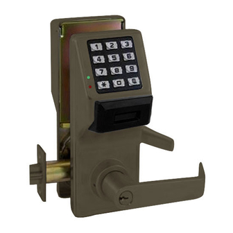
GENERAL DESCRIPTION
This double-sided stand-alone door lock provides con-
trolled entry and exit at locations such as airport security
areas and police stations. The PDL5300 features an
HID compatible ProxCard
and PDL5300 feature a real-time clock/calendar that
automatically adjusts for Daylight Saving Time and al-
lows for automated programming of events.
Double-Sided Description
Both sides of the lock contain keypads, keyholes, levers
and proximity readers. To differentiate between the two
sides of the lock, these instructions refer to the "primary"
side and the "secondary" side. The primary side con-
tains the ribbon cable; inserting the metal key into its
lock cylinder will always unlock the latch, allowing entry
or exit. The secondary side contains no wires; insert-
ing the metal key into its lock cylinder will NEVER unlock
the latch. The key inserted into the secondary side
ONLY allows removal / installation of the secondary
side lever.
RIBBON
CABLE
"PRIMARY SIDE"
Note: Even if the secondary side screws were tam-
pered with and removed--and the secondary side
lever removed--the lock is specifically designed to not
be mechanically unlocked from the secondary side.
Important: Because the metal key will not unlock the
latch from the secondary side, we highly recommend
that this lock never be installed into the sole exit door of a
room. You must thoroughly consider all situations (such
as panic exit due to fire) before deciding where this lock
is to be installed and which side of the lock will be in-
stalled on which side of the door.
Double-Sided DL5200, DL5300 & PDL5300
Installation Instructions
®
reader, and both the DL5300
BATTERY
COMPARTMENT
"SECONDARY SIDE"
Trilogy
DOOR PREPARATION
C
L
OF DOOR
EDGE
1-3/4" (44MM)
OR
1-3/8" (35MM)
DOOR
THICKNESS
FIG. 1: FOLD AND PLACE TEMPLATE ON DOOR
1. Fold and place template on high edge of door at the
recommended height from floor. See Fig. 1.
2. Mark hole centers on door and door edge.
3. Drill 3/8" thru-bolt holes first, then drill 2 1/8" hole.
For Hardwood Doors:
Notch on both sides of 2 1/8" hole to accommodate
mounting plate tabs.
MAIN PROCEDURES
GENERAL DESCRIPTION .............................................. 1
DOOR PREPARATION ................................................... 1
INSTALLATION JIG ...................................................... 2
LATCH INSTALLATION ............................................... 2
STRIKE INSTALLATION .............................................. 2
LOCK PREPARATION ..................................................... 2
ADJUSTING FOR DOOR THICKNESS ...................... 3
TO REVERSE LEVER HANDING ............................... 3
LOCK INSTALLATION .................................................. 3-5
INTERCHANGEABLE (IC) LOCKS ............................... 5
INSTALL INTERCHANGEABLE (IC) CORES .............. 5
CHANGING AN EXISTING IC CORE ............................. 6
REMOVING THE IC CORE & LEVER ............................ 6
PROGRAMMING ....................................................... 6
TROUBLESHOOTING ............................................... 6
WIRE CONNECTIONS .............................................. 7
NAPCO LIMITED WARRANTY ....................................... 8
WI1623B 10/08
HORIZONTAL
C
L
OF
LEVER
MARK
HEIGHT
LINE
VERTICAL
C
L
OF
LOCK
1
Advertisement
Table of Contents

Subscribe to Our Youtube Channel
Related Manuals for Alarm Lock Trilogy DL5200


Summary of Contents for Alarm Lock Trilogy DL5200
-
Page 1: Table Of Contents
Installation Instructions For Sales and Repairs 1-800-ALA-LOCK For Technical Service 1-800-645-9440 Publicly traded on NASDAQ Symbol: NSSC © ALARM LOCK 2008 WI1623B 10/08 GENERAL DESCRIPTION DOOR PREPARATION This double-sided stand-alone door lock provides con- trolled entry and exit at locations such as airport security HORIZONTAL areas and police stations. -
Page 2: Installation Jig
While 1. If 2 1/8" hole already exists, use optional Alarm Lock depressing the lever catch, pull off lever. See Fig. 6 for Installation Jig to ensure accurate locating and drilling an image of the lever catch. -
Page 3: Adjusting For Door Thickness
2. Use the primary side spindle to rotate the lock body ADJUSTING FOR DOOR THICKNESS 180 degrees. Be sure lever catch (shown in Fig. 6) Plastic spacers either add or subtract the distance be- faces the door edge. If necessary, depress the lever tween the roses. - Page 4 The latch yoke must engage the lock body housing and mounting plate pulls in and secures the primary side the tailpiece must engage the retractor. lock body to the door. IMPORTANT: See Fig. 11 and 13: The motor wire must come through either slot and be secured by the INSTALL SECONDARY SIDE LOCK BODY motor cable notch without pinching or cutting the wire.
-
Page 5: Interchangeable (Ic) Locks
Skip to the section, "INTERCHANGEABLE (IC) into primary side core. Note: Tailpieces are used in LOCKS" below. © primary side cores only. Use ONLY an Alarm Lock core tailpiece. Standard Levers and Cylinders: 4. With control key in primary side core, insert core fully Standard levers and standard lock cylinders are both into lever. -
Page 6: Changing An Existing Ic Core
Set core aside. until lock resets, then reconnect and start program- 2. Insert Alarm Lock tailpiece with washer into new core. ming again. 3. Insert new control key into new core, turn clockwise. -
Page 7: Wire Connections
Latch will not fully retract. • Lock is not properly engaged with latch or mis- aligned. Lock is not centered on door (See Fig. 10). Key binds in lock. • Lever catch not fully engaged. Lock is not centered on door. Check for proper tailpiece and proper ori- entation of tailpiece (See Figs. -
Page 8: Napco Limited Warranty
ALARM LOCK will, In no event shall ALARM LOCK be liable for an within said period, at its option, repair or replace any amount in excess of ALARM LOCK's original selling...
Need help?
Do you have a question about the Trilogy DL5200 and is the answer not in the manual?
Questions and answers
can a latch be held in the retracted mode when using a door opener