Table of Contents
Advertisement
345 Bayview Avenue, Amityville, New York 11701
For Sales and Repairs 1-800-ALA-LOCK
For Technical Service 1-800-645-9440
or visit us at
http://tech.napcosecurity.com/
(Note: Technical Service is for security professionals only)
Publicly traded on NASDAQ
Symbol: NSSC
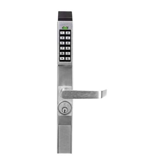
GENERAL DESCRIPTION
The DL1300NW and PDL1300NW are keypad programmable or
wirelessly programmable (through DL-Windows software) nar-
row stile entry trim for Adams Rite
4900 deadlatch locks, and 1850, 1950, 4070, MS1850S and
MS1950S series deadbolts for narrow stile aluminum doors*.
Models
DL1325NW,
PDL1350NW are for use with Adams Rite MS1850S, MS1950,
MS1850S-050 and MS1950-050.
The DL1300NW and PDL1300NW will retract the existing Ad-
®
ams Rite
latch when an access code is entered (or a credential
is presented) and the lever is pressed down (or the turnpiece
turned). The trim is designed to operate with any Adams Rite
interior device such as a "pushpaddle" or lever. Because Ad-
®
ams Rite
trim exists on the inside, the "hold-back feature re-
mains operational for a continuous unlatched function (see Ad-
®
ams Rite
instructions).
code activates latched passage mode (device is unlocked but
the lever or turnpiece is engaged continuously) until another
passage mode function code is entered, re-locking the trim. All
locks are equipped with a mechanical metal key override. For
programming information, visit our Technical Library at
tech.napcosecurity.com/
tions for the PDL1300NW (WI2258) and DL1300NW (WI2264).
MECHANICAL FEATURES
The overall enclosure housing is 15-5/16" inches high, 1-5/8"
inches deep and 1-¾" inches wide. The trim is through-bolted to
the stile of the door (using four #10 screws) and are secured on
the interior side of the door. Supported stile thickness is 1-¾".
DL1300NW and PDL1300NW models support 5000 users
and includes 36,000-event audit trail and 500 event sched-
ule. Keypad or PC programmable
Aluminum door retrofit outside trim for Adams Rite
1950, 4710, 4070, 4730, 4900, MS1850S and MS1950S
Series locks
All-metal, vandal-resistant 12-button keypad supports 3-6
digit PIN codes, and multilevel user hierarchy (master,
manager, supervisor and basic users)
Keypad or PC programmable (see model information).
Quickly and easily add or delete users and enter "passage
mode", service codes, group lock-out & group-enable
PDL1300NW supports proximity ID cards, keyfobs and
proximity tags with its integral proximity reader (high securi-
© ALARM LOCK 2017
®
4510, 4530, 4710, 4730 and
DL1350NW,
PDL1325NW
Entering a passage mode function
and download programming instruc-
DL1300NW & PDL1300NW
NARROW STILE ACCESS LOCKS
MOUNTING AND INSTALLATION
INSTRUCTIONS
ty applications can require use of both PIN code plus prox-
imity credential for access)
Real time clock and PC programmable automatic lock/
unlock scheduling for 500 events
Wide weatherproof operating range from -31ºF to 151ºF
(-35ºC to 66ºC)
and
Provides 50,000 operations using 4AA batteries; includes
audible and visual low battery alert
Non-handed; fully field-reversible
Mechanical key override; interchangeable cores supported
(Corbin/Russwin, Yale, Schlage, Medeco)
®
Mortise Cylinder, 1-¼" supplied (supports 1-1/8", 1-¼",
1-3/8" and 1-½"
Backsets 31/32",1-1/8" and 1-½"; stile thickness 1-¾"
http://
GENERAL DESCRIPTION ...................................... 1
MECHANICAL FEATURES ..................................... 1
MOUNTING AND INSTALLATION ......................... 2
INSTALL CYLINDER ........................................... 3
®
1850,
INSTALL LEVER ................................................. 4
INSERT INTERFACE CYLINDER .................4
INSTALL LOCK ...............................................6
CONNECT BATTERIES..................................6
TEST OPERATION .................................................. 7
ALARM LOCK LIMITED WARRANTY .................... 8
*Adams Rite Manufacturing Co., Pomona, CA. www.adamsrite.com. All products, product names and services
described in this manual are for identification purposes only and may be trademarks of their respective companies.
TABLE OF CONTENTS
WI2257LF 10/17
1
Advertisement
Table of Contents

Related Manuals for Alarm Lock DL1300NW


Summary of Contents for Alarm Lock DL1300NW
- Page 1 PDL1350NW are for use with Adams Rite MS1850S, MS1950, MS1850S-050 and MS1950-050. audible and visual low battery alert Non-handed; fully field-reversible The DL1300NW and PDL1300NW will retract the existing Ad- Mechanical key override; interchangeable cores supported ® ams Rite...
- Page 2 HW1331 1-½ HW1342 Cylinder Collars: The DL1300NW and PDL1300NW can use a 1-⅛" & 1-¼" mortise cylinder without the use of a collar (1-¼" requires two plastic spacers, supplied). For cylinders longer than 1-¼" a collar is required. Cam for Mechanical Override Cylinder...
- Page 3 Note: The trim is manufactured to use a 1-1/8" or 1-¼" Alarm Lock mortise cylinder with a HW-1302 cam. If the cylinder that will be used is longer than 1-¼", a col- lar must be utilized.
- Page 4 Install the Lever Insert the Interface Cylinder 3. Install the lever with proper orientation for 5. Loosen the set screw, then remove the outside cylin- the lock/door hand used. der (if present--See Fig. 5). Tighten the set screw us- Remove the Adams Right set screw, and replace with ing a 1/8"...
- Page 5 5c. The interface cylinder must be centered and posi- 5f. Verify the face of the interface cylinder (" HW1824" ) tioned flush with (or slightly below) the surface of the door is positioned parallel to the surface of the door. (see Fig.
- Page 6 Install Lock Plug in the battery connector and insert the battery pack 6. Install the DL lock onto the door by aligning the two into the battery compartment. Neatly push all wiring posts on the front of the interface cylinder with the two inside the compartment and on the side of the battery corresponding holes in the back of the DL lock.
- Page 7 6. Test the exit device mounted inside (paddle / egress bar, etc.) and confirm it is operating correctly. For programming information, visit our Technical Library at http://tech.napcosecurity.com/ and download programming instructions for the PDL1300NW (WI2258) and DL1300NW (WI2264). Test Step 3...
- Page 8 This warranty shall not apply to any equipment, or any part In no event shall ALARM LOCK be liable for an amount in thereof, which has been repaired by others, improperly excess of ALARM LOCK's original selling price of the...
Need help?
Do you have a question about the DL1300NW and is the answer not in the manual?
Questions and answers