Alarm Lock DL1300 Programming Instructions Manual
Hide thumbs
Also See for DL1300:
- Mounting and installation instructions manual (20 pages) ,
- Brochure (4 pages) ,
- Datasheet (2 pages)
Table of Contents
Advertisement
DL1300
Programming Instructions
345 Bayview Avenue
Amityville, New York 11701
For Sales and Repairs 1-800-ALA-LOCK
For Technical Service 1-800-645-9440
OI311 7/06
© ALARM LOCK 2006
Publicly traded on NASDAQ Symbol: NSSC
AL-IR1 PRINTER
AL-DTM
DATA TRANSFER
MODULE
DL-WINDOWS PROGRAMMING
SOFTWARE
DL1300
DL Trilogy Series
Stand-Alone Access Control Systems
1
Advertisement
Table of Contents

Related Manuals for Alarm Lock DL1300


Summary of Contents for Alarm Lock DL1300
-
Page 1: Programming Instructions
DL1300 Programming Instructions 345 Bayview Avenue Amityville, New York 11701 For Sales and Repairs 1-800-ALA-LOCK For Technical Service 1-800-645-9440 OI311 7/06 © ALARM LOCK 2006 Publicly traded on NASDAQ Symbol: NSSC AL-IR1 PRINTER AL-DTM DATA TRANSFER MODULE DL-WINDOWS PROGRAMMING SOFTWARE... -
Page 2: Table Of Contents
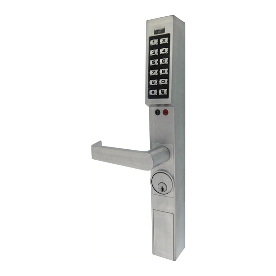
EYPAD NTRY ECURITY DL1300 Your new DL1300 Alarm Lock Trilogy electronic digital lock is a mortise- ® based manually programmable narrow stile entry trim for Adams Rite 4710, 4730 and 4900 deadlatch locks, and 1850, 1950, 4070, MS1850S and MS1950S series deadbolts for narrow stile aluminum doors*. -
Page 3: Dl1300 Series Lock Features
User Lockout Mode (see page 16, Function 6) • Users Assignable to 4 Groups (see page 27) Keypad and Computer Programming • All programming may be performed manually from the keypad, or from a PC using Alarm Lock's DL- Windows Software (see page 5) -
Page 4: Supported Products
Its infrared reader means no cable connection to the lock is needed. AL-PCI Cable An ALARM LOCK AL-PCI cable is required to communicate between your computer’s RS-232 serial communications port (COM 1-4) and the AL-DTM or lock. One end of the AL-PCI cable is designed to be used on a 9-pin serial Com Port. -
Page 5: Lock Design Overview
The answer lies in the advantage of software. Software (also called "firmware") is not "hard" or "fixed" like hardware is. Software is "soft" -- flexible and changeable to your needs. Software exists inside your Alarm Lock™ series lock, and can be programmed (and re-programmed again and again) to suit your changing requirements. -
Page 6: Terminology Used In This Manual
Terminology Used in this Manual What is a Lock Program? What is a Programming Level? A Lock Program contains the instructions that a lock uses to The Programming Level defines the range of programming perform its various functions. You can use the keypad to cre- tasks a User is allowed to perform. - Page 7 DL-Windows is a computer program that allows you to pro- Group associations are specified in the tables on page 8. For gram your ALARM LOCK security lock. You do not need DL- example, if you wish to add a User to Group 1, assign this Windows to program your lock, but it makes programming User a User Number between 51 and 100.
-
Page 8: Programming Levels
Programming Levels The Programming Level defines the range of programming Manager: Always associated with Users 4, 5, and 6. Can tasks a User is allowed to perform. The higher the Level, the program all functions except functions relating to lock more programming tasks the User is allowed (with Master al- configuration. -
Page 9: Conventions Used In This Manual
Conventions Used in this Manual Enabling/Disabling Users (By User Number) Minimum Required Program Level User Number must be between 2 and 2000. Program Levels are abbreviated as follows: NOTE: Will Enable/Disable users even if the user is associated with an enabled group. Function M = Master Description... -
Page 10: Product Communication Examples
Product Communication Examples Send to lock Receive from lock If your computer does not have a serial COM port AL-PCI CABLE (DB-9 male) available, you can plug your AL-PCI2 CONNECT TO SERIAL PORT cable into a special USB to RS-232 cable. Order (COM 1-4) part PCI-USB for the USB to RS-232 cable... -
Page 11: Wiring And Power Up
Wiring and Power Up WIRING directly to ALTERNATIVE METHOD, below). Wait for the green light and press ; until multiple beeps are See the Installation Manual for more information. heard. You are now in Program Mode. Batteries: 2. Press ; 99 ; 000 :. Use only 3.0 volt Lithium Type 123 batteries (or equiva- lent). -
Page 12: Quick Start
Quick Start First Time Start Up 1. Unpack the lock. 2. With the batteries disconnected, hold down the ; key for 10 seconds and release. 3. Connect the batteries and listen for 3 beeps. 4. Wait 15 seconds, and listen for 6 additional beeps (LED will flash twice). The lock is ready to program when it unlocks. -
Page 13: Testing The Codes Entered
Quick Start (cont’d) Delete a User Code 1. Enter Program Mode (if not in already). 2. Press ; 2 ; [User Number] :. The lock will flash a green LED and beep continuously for 6 seconds. When the red LED flashes, the User Code is deleted. -
Page 14: Programming Functions Overview
Programming Functions--Overview Function 1 Change Master Code See page 15 Function 48 Enable Passage Mode See page 21 Function 2 Add/Delete/Change User Codes See page 15 See page 21 Function 49 Disable Passage Mode See page 16 Function 3 User Disable (By User Number) See page 21 Function 50 Return Lock to Normal Passage... -
Page 15: Programming Functions
Programming Functions USERS 1. New Master Code [ _ _ _ _ _ _ ] [ _ _ _ _ _ _ ] (User Number 1) (New Master Code) (Confirm New Master Code) • Master Code must be 6 digits-only. •... - Page 16 Programming Functions (cont'd) USERS (Continued) User Enable/Disable (By User Number) • User Number must be between 2 and 2000. NOTE: Will Enable/Disable Users even if the User is associated with an enabled Group. Use Feature 3 to disable a specific User Number and their associated User Code.
- Page 17 Programming Functions (cont'd) CLEAR FUNCTIONS 12. Clear All Schedules and Timeout Functions ; 1 2 ; 0 0 0 : Function 12 clears all programmed Schedules and all Timeout Functions. (To clear All Timeout Functions only, see Function 13 below). Function 12 will clear all of the following: All Schedule Functions 72 through 93, Timeout Functions 5, 25 through 34 and Function 47.
- Page 18 Programming Functions (cont'd) NOTE: Clear All Timeout Functions by entering Function 13. GROUPS Group Enable/Disable with Timeout (Enter Timeout, XXX Hours) (Functions 25-34 are enabled through the keypad only) • Hours must be between 1-999. Enter the functions below to Enable/Disable Groups for the amount of time entered in hours. NOTE: Only 4 Timeout Functions are allowed at any one time.
- Page 19 Programming Functions (cont'd) CLOCK SETTINGS 38. Set Date [ _ _ _ _ _ _ ] ; 3 8 (Date) • Use Month Day Year format - MMDDYY - Single digit months and days are entered with a preceding zero. •...
- Page 20 Programming Functions (cont'd) CLOCK ADJUST Clock Adjust Number of seconds to adjust (speed up/slow down) the clock each day must be between 0-55 seconds. Note: Repeated use of these Functions are not "cumulative" (this means, for example, if the clock has already been set to speed up 10 seconds per day, and then is found to Clock Accuracy need an additional 10 seconds, then program 20 seconds using Function 43).
- Page 21 Programming Functions (cont'd) PERMANENT PASSAGE MODE Passage Mode Enable/Disable - Schedule will not Override • Function 48 allows passage through the door without the need for a User Code. Re-Lock using Function 49. • Programmed Schedules will not override the state of the lock using functions 48 and 49. If it is required that programmed schedules override Passage Mode, Enable/Disable Passage Mode using Functions 45/46.
- Page 22 Programming Functions (cont'd) PRINTER Hold the printer's infrared reader in front of the lock’s infrared LED as shown in Figure 1 and Figure 2 below. If the printer has been idle for some time, press the paper feed button to wake up the printer. Infrared Infrared Infrared...
- Page 23 Programming Functions (cont'd) 59. Reserved LOCKOUT [ _ ] 60. Number of Attempts Before Lockout ; 6 0 (Number of Attempts) • Number of attempts before lockout must be 1-9 attempts. • The number of attempts is reduced by half every time the keypad is locked out without a successful code entry (default is 6 attempts).
-
Page 24: Enter Key
Programming Functions (cont'd) ENTER KEY Enter Key • When this function is enabled, the User must press after any valid User Code entry. Therefore, this Function allows User Codes to be subsets of other User Codes. Examples: 1 2 3 : can be a valid user code; 1 2 3 4 : a valid user code within the same lock. - Page 25 Programming Functions (cont'd) QUICK SCHEDULES Quick Schedules - Enable Group For your convenience, your lock comes pre-programmed with Quick Schedules, which, when programmed, enable Groups for popular blocks of time. Group members will be enabled during the blocks of time defined below, but will still need to enter their User Codes into the keypad to unlock the lock.
- Page 26 Programming Functions (cont'd) Scheduled Group 4 Enable (Group 1 Activated) Functions 92 and 93 allow you to set up a window of time where if any Group 1 User Code is entered within this window, Group 4 members will be enabled. (Group 4 members will still need to enter their User Codes to enter). For additional information, see Group 1 Activated Features on page 27.
-
Page 27: Groups And Scheduled Group 1 Examples
DL-Windows software to program your Alarm Lock security lock. For more information, contact your Alarm Lock security professional. Assign a User to Two Groups Create a User 101 (all Users 101-150 are members of Group 2 by default) and include User 101 in Group 3 (as well as the default Group 2). - Page 28 Groups and Scheduled Group 1 Examples (cont'd.) Functions 92/93: Use Function 92 and 93 (see page 26) to create a window of time where if any Group 1 User Code is entered within the programmed window, Group 4 Users will be enabled. 1.
-
Page 29: Programming Record Sheet
Default Values are shown in parentheses. Function Number(s) Function Name Programming 43/44 Clock Adjust 0-55 Seconds 52/53/54 Pass Time (3 sec) 10 sec 15 sec Set Lockout Attempts 1-9 Attempts Set Lockout Time 1-60 seconds 69/70 Enter Key Enable (Disable) -
Page 30: User Code Record Sheet
User Number User Code Group User Name (1-2000) (3-6 digits) Association Note: For a complete list of user codes, obtain a printout from either the remote printer (Program Function 56) or using the DL-WINDOWS Software. - Page 31 User Number User Code Group User Name (1-2000) (3-6 digits) Association Note: For a complete list of user codes, obtain a printout from either the remote printer (Program Function 56) or using the DL-WINDOWS Software.
- Page 32 User Number User Code Group User Name (1-2000) (3-6 digits) Association Note: For a complete list of user codes, obtain a printout from either the remote printer (Program Function 56) or using the DL-WINDOWS Software.
-
Page 33: Schedule Record Sheet
Day(s) Up to 500 scheduled functions can be programmed. For Day Enter: 1 = Sunday, 2 = Monday, 3 = Tuesday, 4 = Wednesday Function Number Time Function Name 5 = Thursday, 6 = Friday, 7 = Saturday, 8 = Monday through Friday, 9 = Saturday and Sunday, 0 = All days of the week Enter Time of Day in 24-hour format (00:00- 23:59) - Page 34 Day(s) Up to 500 scheduled functions can be programmed. For Day Enter: 1 = Sunday, 2 = Monday, 3 = Tuesday, 4 = Wednesday Function Number Time Function Name 5 = Thursday, 6 = Friday, 7 = Saturday, 8 = Monday through Friday, 9 = Saturday and Sunday, 0 = All days of the week Enter Time of Day in 24-hour format (00:00- 23:59)
-
Page 35: Glossary
Glossary number. (Used with AL-DTM Transfer Module) ACCESS = Entry into a restricted area. AUDIT TRAIL = A date/time stamped log of previous lock events. DOWNLOAD = Send data to lock or AL-DTM. CLOCK ENABLE = Turn on. EVENTS = Recorded lock activity. •... -
Page 36: Limited Warranty
ALARM LOCK is not an insurer of either the property or safety of the user's family or employees, and limits its liability for any loss or damage including incidental or consequential damages to ALARM LOCK's original selling price of the product regardless of the cause of such loss or damage.
Need help?
Do you have a question about the DL1300 and is the answer not in the manual?
Questions and answers
dimensions showing distance with lock cylender
The Alarm Lock DL1300 has a standard door thickness requirement of 1-3/4 inches. It also supports door thicknesses ranging from 1-5/8 inches to 1-7/8 inches. The available cylinder dimensions are 31/32 inches and 1-1/8 inches.
This answer is automatically generated