Table of Contents
Advertisement
Trilogy
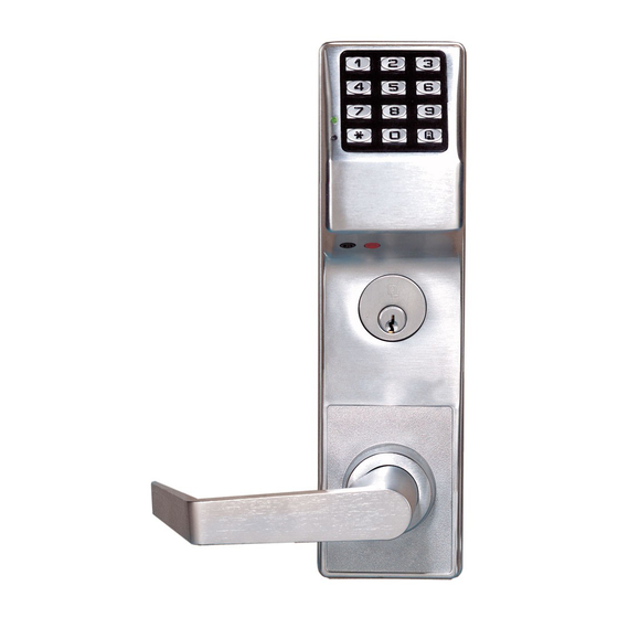
DL3500, DL3500EX, ETDL & DL3200
345 Bayview Avenue
Amityville, New York 11701
Programming Instructions
For Sales and Repairs 1-800-ALA-LOCK
For Technical Service 1-800-645-9440
Publicly traded on NASDAQ
Symbol: NSSC
© ALARM LOCK 2005
WI1005C 11/05
DL3200
DL3500
DL3500EX
ETDL
DL-Windows
AL-DTM
AL-IR1 PRINTER
DATA TRANSFER
MODULE
Alarm Lock Trilogy Series
Stand-Alone Access Control Systems
1
Advertisement
Table of Contents

Related Manuals for Alarm Lock Trilogy ETDL


Summary of Contents for Alarm Lock Trilogy ETDL
-
Page 1: Programming Instructions
DL3500, DL3500EX, ETDL & DL3200 345 Bayview Avenue Amityville, New York 11701 Programming Instructions For Sales and Repairs 1-800-ALA-LOCK For Technical Service 1-800-645-9440 Publicly traded on NASDAQ Symbol: NSSC © ALARM LOCK 2005 WI1005C 11/05 DL3200 DL3500 DL3500EX ETDL DL-Windows AL-DTM... -
Page 2: Table Of Contents
DL SERIES LOCKS DL-S LARM RILOGY ERIES TAND LONE CCESS ONTROL YSTEM IS A SERIES OF TATE ICROPROCESSOR ASED ROGRAMMABLE EYPAD NTRY ECURITY OCKS DL3500, DL3500EX, DL3200 & ETDL Features a real-time clock/calendar that automatically adjusts for Daylight Sav- ing Time and allows for automated programming of events. Features three methods of programming: (1) all features can be programmed manually through the keypad;... -
Page 3: Dl Series Lock Features
Users Assignable to 4 Groups (see page 18) • Ambush Function (see page 23, Function 66) Keypad and Computer Programming • All programming may be performed manually from the keypad, or from a PC using Alarm Lock's DL- Windows Software (see page 4) -
Page 4: Supported Products
AL-PCI Cable An ALARM LOCK AL-PCI cable is required to communicate between your computer’s RS-232 serial com- munications port (COM 1-4) and the AL-DTM or lock. One end of the AL-PCI cable is designed to be used on a 9-pin serial Com Port. -
Page 5: Lock Design Overview
The answer lies in the advantage of software. Software (also called "firmware") is not "hard" or "fixed" like hardware is. Software is "soft" -- flexible and changeable to your needs. Software exists inside your Alarm Lock™ series lock, and can be programmed (and re- programmed again and again) to suit your changing requirements. -
Page 6: Terminology Used In This Manual
Terminology Used in this Manual What is a Lock Program? tasks a User is allowed to perform. The higher the Level, the more programming tasks the User is allowed (with Master al- A Lock Program contains the instructions that a lock uses to lowing ALL tasks). - Page 7 DL-Windows is a computer program that allows you to pro- Who are Users 297-300? gram your ALARM LOCK T3 Security Lock. You do not need DL-Windows to program your lock, but it makes programming Users assigned to User Numbers 297, 298, 299 and 300 have much faster and easier.
-
Page 8: Programming Levels
Programming Levels The Programming Level defines the range of programming tasks as Programming Level = 4). a User is allowed to perform. The higher the Level, the more pro- Manager: Always associated with Users 4, 5, and 6. Can pro- gramming tasks the User is allowed (with Master allowing ALL gram all functions except functions relating to lock tasks). -
Page 9: Conventions Used In This Manual
Conventions Used in this Manual Enabling/Disabling Users (By User Number) Minimum Required Program Level User Number must be between 2 and 2000. (DL3500 Series locks allow up to 300 Users). Program Levels are abbreviated as follows: NOTE: Will Enable/Disable users even if the user is associated with an enabled group. Function M = Master Description... -
Page 10: Product Communication Examples
Product Communication Examples Send to lock Receive from lock AL-PCI CABLE CONNECT TO SERIAL PORT (COM 1-4) NOTE: OBSERVE TAB DIRECTION WHEN INSERTING CABLE INTO LOCK IBM COMPATABLE DL3200 LAPTOP OR DESKTOP PC Scenario 1 Create the program in DL-Windows on your computer, then transfer the program from the computer directly to the lock via an AL-PCI cable. -
Page 11: Wiring And Power Up
Wiring and Power Up WIRING 5. A series of 5 RED LED and 5 beeps will be heard followed by 10 seconds of silence, then 3 GREEN LEDs and 3 fast See the Installation Manual for more information. beeps. All settings and programming have been erased and the lock Batteries: is now ready for use. -
Page 12: Quick Start
Quick Start First Time Start Up 1. Unpack the lock. 2. With the batteries disconnected, hold down the ; key for 10 seconds and release. 3. Connect the batteries and listen for 3 beeps. Within 5 seconds of hearing the 3 beeps, press and hold ; until beeping starts. -
Page 13: Testing The Codes Entered
Quick Start (cont’d) The lock will flash a green LED and beep continuously for 6 seconds. When the red LED flashes, the User Code is deleted. 3. Repeat step 2 for each new User. User Code Conflicts Care should be taken not to program a new User Code which matches the first digits of any other User Code (only the User Code with the least number of digits will be recognized). -
Page 14: Programming Functions Overview
Programming Functions--Overview Function 1 Change Master Code See page 15 Function 48 Enable Passage Mode See page 21 Function 2 Add/Delete/Change User Codes See page 15 Function 49 Disable Passage Mode See page 21 Function 50 Return Lock to Normal Passage See page 21 Function 3 User Disable (By User Number) -
Page 15: Programming Functions
Programming Functions USERS 1. New Master Code [ _ _ _ _ _ _ ] [ _ _ _ _ _ _ ] (User Number 1) (New Master Code) (Confirm New Master Code) • Master Code must be 6 digits-only. •... - Page 16 Programming Functions (cont'd) USERS (Continued) User Enable/Disable (By User Number) • User Number must be between 2 and 2000. NOTE: Will Enable/Disable Users even if the User is associated with an enabled Group. Use Feature 3 to disable a specific User Number and their associated User Code.
- Page 17 Programming Functions (cont'd) CLEAR FUNCTIONS 12. Clear All Schedules and Timeout Functions ; 1 2 ; 0 0 0 : Function 12 clears all programmed Schedules and all Timeout Functions. (To clear All Timeout Functions only, see Function 13 below). Function 12 will clear all of the following: All Schedule Functions 72 through 93, Timeout Functions 5, 25 through 34 and Function 47.
- Page 18 Programming Functions (cont'd) NOTE: Clear All Timeout Functions by entering Function 13. GROUPS Group Enable/Disable with Timeout (Enter Timeout, XXX Hours) (Functions 25-34 are enabled through the keypad only) • Hours must be between 1-999. Enter the functions below to Enable/Disable Groups for the amount of time entered in hours. NOTE: Only 4 Timeout Functions are allowed at any one time.
-
Page 19: Set Date
Programming Functions (cont'd) CLOCK SETTINGS 38. Set Date [ _ _ _ _ _ _ ] ; 3 8 (Date) • Use Month Day Year format - MMDDYY - Single digit months and days are entered with a preceding zero. •... - Page 20 Programming Functions (cont'd) CLOCK ADJUST Clock Adjust Number of seconds to adjust (speed up/slow down) the clock each day must be between 0-55 seconds. Always consider the current setting when using this function, because this function is not cumulative. For example, if the clock needs to be sped up 10 seconds per day and the current setting is already 10, program 20 seconds using Function 43 (below).
- Page 21 Programming Functions (cont'd) PERMANENT PASSAGE MODE Passage Mode Enable/Disable - Schedule will not Override • Function 48 allows passage through the door without the need for a User Code. Re-Lock using Function 49. • Programmed Schedules will not override the state of the lock using functions 48 and 49. If it is required that programmed schedules override Passage Mode, Enable/Disable Passage Mode using Functions 45/46.
- Page 22 Programming Functions (cont'd) PRINTER Hold the printer perpendicular to the Lock’s infrared LED as shown in Figure 1 and Figure 2. If the printer has been idle for some time, press the paper feed button to wake up the printer. Infrared Infrared DL4100 to Printer...
- Page 23 Programming Functions (cont'd) AL-DTM2 [ _ _ ] ; 5 9 59. AL-DTM Door Number (Door Number) *With the introduction of DL-Windows v3.5.1 and the AL-DTM-III (and future versions of these products), Function 59 is no longer used. The description below is for use with older versions of DL-Windows (and AL-DTM versions 1 and 2) and is included here for reference only.
-
Page 24: System Options
Programming Functions (cont'd) SYSTEM FEATURES [ _ _ ] ; 6 7 67. Add System Features (Event Number) • Relay Features (12-24. Reserved) Use Function 67 to program one or more lock events and the Relay will energize when the programmed event(s) listed below oc- curs. -
Page 25: Enter Key
Programming Functions (cont'd) ENTER KEY Enter Key • When this function is enabled, the User must press after any valid User Code entry. Therefore, this Function allows User Codes to be subsets of other User Codes. Examples: 1 2 3 : can be a valid user code; 1 2 3 4 : a valid user code within the same lock. - Page 26 Programming Functions (cont'd) QUICK SCHEDULES Quick Schedules - Enable Group For your convenience, your lock comes pre-programmed with Quick Schedules, which, when programmed, enable Groups for popular blocks of time. Group members will be enabled during the blocks of time defined below, but will still need to enter their User Codes into the keypad to unlock the lock.
- Page 27 Programming Functions (cont'd) SCHEDULES GROUP 1 ACTIVATED Scheduled Relay Activation (Group 1 Activated) Functions 90 and 91 allow you to set up a window of time where if any Group 1 User Code is entered within this window, the relay will be activated for 2 seconds. This relay is for use with a Control Panel that has a key switch disarm option. For additional information, see Group 1 Activated Features on page 29.
- Page 28 Programming Functions (cont'd) Scheduled Group 4 Enable (Group 1 Activated) Functions 92 and 93 allow you to set up a window of time where if any Group 1 User Code is entered within this window, Group 4 members will be enabled. (Group 4 members will still need to enter their User Codes to enter). For additional information, see Group 1 Activated Features on page 29.
-
Page 29: Groups And Scheduled Group 1 Examples
The following examples detail the more advanced features of the DL series locks. Although all features and device functions can be programmed using the lock keypad, when programming becomes more complex you may find it easier to use DL-Windows software to program your Alarm Lock security lock. - Page 30 Groups and Scheduled Group 1 Examples (cont'd.) Functions 90/91: Use Function 90 and 91 (see page 27) to create a window of time where if any Group 1 User Code is entered within the programmed window, a Relay will be activated for 2 seconds. The Relay can be configured to disarm a burglary control panel. See page 27. 1.
-
Page 31: Programming Record Sheet
Default Values are shown in parentheses. Function Number(s) Function Name Programming Daylight Saving Time Code 01-24 DST Code 43/44 Clock Adjust 0-55 Seconds 52/53/54 Pass Time (3 sec) 10 sec 15 sec AL-DTM Door Number 1-96 (48 for AL-DTM (Version 1) Door Number Set Lockout Attempts 1-9 Attempts... -
Page 32: User Code Record Sheet
User Number User Code Group User Name (1-2000) (3-6 digits) Association Note: For a complete list of user codes, obtain a printout from either the remote printer (Program Function 56) or using the DL-WINDOWS Software. -
Page 33: Schedule Record Sheet
Day(s) Up to 500 scheduled functions can be programmed (Up to only 150 using AL-DTM). For Day Enter : 1 = Sunday, 2 = Monday, 3 = Tuesday, 4 = Wednesday Function Number Time Function Name 5 = Thursday, 6 = Friday, 7 = Saturday, 8 = Monday through Friday, 9 = Saturday and Sunday, 0 = All days of the week Enter time of day in 24-hour format (00:00- 23:59) -
Page 34: Glossary
Glossary • ACCESS = Entry into a restricted area. SERVICE CODE = User 300 User Code. Allows only one entry, then needs to be re-enabled by the User 297 User Code to regain access. AMBUSH = A special Code entered at the keypad when the User is forced to unlock a device. - Page 35 Glossary (cont'd) alarm panel must be armed through other means (such as an Alarm Panel Keypad). The Burglary Alarm Panel must be PROGRAMMABLE RELAY FUNCTIONS = The relay can be programmed to disarm from an Armed State Only and the programmed for one or more functions.
-
Page 36: Warranty
ALARM LOCK is not an insurer of either the property or safety of the user's family or employees, and limits its liability for any loss or damage including incidental or consequential damages to ALARM LOCK's original selling price of the product regardless of the cause of such loss or damage.
Need help?
Do you have a question about the Trilogy ETDL and is the answer not in the manual?
Questions and answers
Mounting Template. Could not find weldable lock box to put in 2" frame Ornamental Gate for Pool