
Related Manuals for Quanmax KPC-1590


Summary of Contents for Quanmax KPC-1590
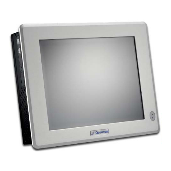
- Page 1 KPC-1590/1790 15”/17” Industrial Panel PC with Intel® GM45 + ICH9-M User’s Guide KPC-1590/ 1790 User’s Manual...
- Page 2 © 2009 Quanmax Inc. All rights reserved. The information in this user’s guide is provided for reference only. Quanmax does not assume any liability arising out of the application or use of the information or products described herein. This user’s guide may contain or reference information and products protected by copyrights or patents and does not convey any license under the patent rights of Quanmax, nor the rights of others.
-
Page 3: Table Of Contents
Panel Mounting ................... 26 Chapter 3 Getting Started ..................28 Power Connection ................28 Operating System and Drivers ............29 Chapter 4 Maintenance and Prevention ..............30 Chapter 5 Interface ....................31 External Connectors ................31 KPC-1590/ 1790 User’s Manual... -
Page 4: Figures
Figure 1 Mechanical Layout - Front and Side ............15 Figure 2 Mechanical Layout - I/O Panel ..............16 Figure 3 Mechanical Dimensions (KPC-1590) ............16 Figure 4 Mechanical Dimensions (KPC-1790) ............17 Figure 5 Removing the rear cover ................18 Figure 6 Mechanical Internal Layout ................ -
Page 5: Tables
Table 6 USB1 (USB2.0 Port 0, 1 Type A Connector) ..........32 Table 7 COM1 RS-232/422/485 (DB9 Male Connector) ........... 33 Table 8 COM2 RS-232 (DB9 Male Connector) ............33 Table 9 Digital I/Os (DB9 Female Connector) ............33 KPC-1590/ 1790 User’s Manual... -
Page 6: Safety Instructions
Use extreme caution when installing or removing components. Refer to the installation instructions in this user’s guide for precautions and procedures. If you have any questions, please contact Quanmax Post-Sales Technical Support. WARNING High voltages are present inside the chassis when the unit’s power cord is plugged into an electrical outlet. -
Page 7: Preventing Electrostatic Discharge
Static electricity can harm system boards. Perform service at an ESD workstation and follow proper ESD procedure to reduce the risk of damage to components. Quanmax strongly encourages you to follow proper ESD procedure, which can include wrist straps and smocks, when servicing equipment. -
Page 8: Preface
Remove all items from the box. If any items listed on the purchase order are missing, notify Quanmax customer service immediately. Inspect the product for damage. If there is damage, notify Quanmax customer service immediately. Refer to “Warranty Policy” for the return procedure. -
Page 9: Warranty Policy
Quanmax or its authorized agent; or if the failure is caused by accident, acts of God, or other causes beyond the control of Quanmax or the manufacturer. Neglect, misuse, and abuse shall include any installation, operation, or maintenance of the product other than in accordance with the user’s guide. -
Page 10: Maintaining Your Computer
Quanmax. Limitation of Liability In no event shall Quanmax be liable for any defect in hardware, software, loss, or inadequacy of data of any kind, or for any direct, indirect, incidental, or consequential damages in connection with or arising out of the performance or use of any product furnished hereunder. -
Page 11: Power Protection
Line conditioners keep a system’s AC power source voltage at a fairly constant level and, therefore, can handle brownouts. Because of this added protection, line conditioners cost more than surge protectors. However, line conditioners cannot protect against a complete loss of power. KPC-1590/ 1790 User’s Manual... - Page 12 UPS systems, and the UPS system should be Underwriters Laboratories (UL) safety approved. CAUTION RISK OF EXPLOSION IF BATTERY IS REPLACED BY AN INCORRECT TYPE. DISPOSE OF USED BATTERIES ACCORDING TO THE INSTRUCTIONS KPC-1590/ 1790 User’s Manual...
-
Page 13: Chapter 1 Introduction
Introduction Overview The KPC-1590/1790 Panel PCs is supporting the latest Intel® 45nm Core 2 Duo processor with the high integration of the Intel® GM45/ ICH9M chipset. Featured are DDR3 SODIMM up to 2GB, Intel® GMA 4500MHD supports DirectX 10 and Shader Model 4.0. -
Page 14: Product Specifications
442 x 354 x 91 mm (W x H x D) Weight 5.9 kg 8.2kg Power Input AC 100-240V(Optional DC-12V or DC-24V) Mounting Type Wall, VESA, Panel Mount Compliant CE, FCC Class A, IP65 front bezel Table 1 Specifications KPC-1590/ 1790 User’s Manual... -
Page 15: Mechanical Layout
Mechanical Layout Front and Side Panel Figure 1 Mechanical Layout - Front and Side WARNING Be sure not to block any air vents on the computer. Blocked air vents can cause thermal problems. I/O Panel KPC-1590/ 1790 User’s Manual... -
Page 16: Figure 2 Mechanical Layout - I/O Panel
Chapter 1 Figure 2 Mechanical Layout - I/O Panel Mechanical Dimensions Figure 3 Mechanical Dimensions (KPC-1590) KPC-1590/ 1790 User’s Manual... -
Page 17: Figure 4 Mechanical Dimensions (Kpc-1790)
Chapter 1 Figure 4 Mechanical Dimensions (KPC-1790) KPC-1590/ 1790 User’s Manual... -
Page 18: Chapter 2 Assembly/Disassembly
1) Place the system front-side-down on a soft material to prevent marking or scratching of the front panel. Remove the screws securing the rear panel of the chassis as shown. Figure 5 Removing the rear cover KPC-1590/ 1790 User’s Manual... -
Page 19: Figure 6 Mechanical Internal Layout
2) Remove the rear cover. Note the locations of the internal components of the system. Figure 6 Mechanical Internal Layout NOTE The system was equipped with SO-DIMM DDR3-RAM. We suggest do not install or remove the RAM by yourself. KPC-1590/ 1790 User’s Manual... -
Page 20: Processor Installation
Align the gold triangle on the CPU with the similar marking on the socket (see Figure below). If the processor does not drop completely into the socket, turn the socket actuator to the open position until the processor drops completely in. KPC-1590/ 1790 User’s Manual... -
Page 21: Removing The Cpu
To remove the CPU, follow Step 2 of Installing the CPU above. Remove the CPU by grasping the substrate edges only with thumb and forefinger and lifting it out with a purely vertical motion. WARNING The CPU and the heat-sink may be hot and could cause burns. KPC-1590/ 1790 User’s Manual... -
Page 22: Cooler Installation
Tighten each screw halfway to secure the cooler assembly to the motherboard. Then gradually tighten all four screws. Do not fully tighten the first screw before partially tightening the other screws as this may apply uneven pressure to the CPU, causing damage. KPC-1590/ 1790 User’s Manual... -
Page 23: Hdd & Odd Installation
Figure 10 HDD & ODD Installation NOTE Above procedure is for KPC-1790 only. If you want to install HDD & ODD in KPC-1590, you have to secure ODD to the ODD bracket and secure the ODD bracket to the chassis first. -
Page 24: Vesa Mounting
Chapter 2 VESA Mounting The product comes with VESA FDMI 75/100 standard mounting holes as shown below. Use 4 screws with the appropriate length for your mounting bracket. Figure 11 Mounting hole locations KPC-1590/ 1790 User’s Manual... -
Page 25: Wall Mounting
Chapter 2 Wall Mounting Below are the demonstrations of how to use Quanmax wall-mount kits Step1 Secure the VESA kit to the panel PC using the 4 screws. Step2 Install the wall-mount kit to the proper place of the wall by using the 6 screws. -
Page 26: Panel Mounting
The Panel PC can be panel mounted and comes with 8 brackets and screws for this purpose. The required cutout for panel mounting and maximum panel thickness is shown below. Figure 13 Panel Mount Cut-out hole and maximum panel thickness KPC-1590/ 1790 User’s Manual... -
Page 27: Figure 14 Panel Mounting
Step3 Insert a Panel Mount Bracket into a bracket opening as shown. Step4 Secure the chassis to the panel by tightening the screw provided against the panel. Repeat for the remaining brackets. Figure 14 Panel Mounting KPC-1590/ 1790 User’s Manual... -
Page 28: Chapter 3 Getting Started
DC 12V (Optional DC 24V) Make sure the power distribution to the DC power feed wires is disconnected. Loosen the screws securing the terminal block to the DC inlet as shown and remove it from the chassis. KPC-1590/ 1790 User’s Manual... -
Page 29: Operating System And Drivers
You can download the drivers for the product from the Quanmax website www.quanmax.com and install as instructed there. For other operating systems, please contact Quanmax. -
Page 30: Chapter 4 Maintenance And Prevention
Chapter 4 Chapter 4 Maintenance and Prevention Your KPC-1590/1790 system requires minimal maintenance and care to keep it operating correctly. Occasionally wipe the system with a soft dry cloth. You should only remove persistent dirt by use of a soft, slightly damp cloth (use only a mild detergent). -
Page 31: Chapter 5 Interface
Signal Name Signal Name TX2N TX2P TX5N TX5P SD_CLK SD_DATA VSYNC TX1N TX1P TX4N TX4P VGA_PWR VGA_EN TX0N TX0P TX6N TX6P TCLP TXLN Signal Name Analog red Analog green Analog blue Analog horizontal sync Analog ground KPC-1590/ 1790 User’s Manual... -
Page 32: Table 4 Hdmi1 (Hdmi1 Connector)
100M link Green on 100M active Green on Blink 1000M link Orange on 1000M active Orange on Blink Table 6 USB1 (USB2.0 Port 0, 1 Type A Connector) Signal Name Signal Name USB1- USB0- USB1+ USB0+ KPC-1590/ 1790 User’s Manual... -
Page 33: Table 7 Com1 Rs-232/422/485 (Db9 Male Connector)
Selected by BIOS Setting Table 9 Digital I/Os (DB9 Female Connector) Signal Signal Digital Output 0 Digital Input 2 Digital Input 0 Digital Output 3 Digital Output 1 Digital Input 3 Digital Input 1 Digital Output 2 Screw KPC-1590/ 1790 User’s Manual...
Need help?
Do you have a question about the KPC-1590 and is the answer not in the manual?
Questions and answers