Table of Contents
Advertisement
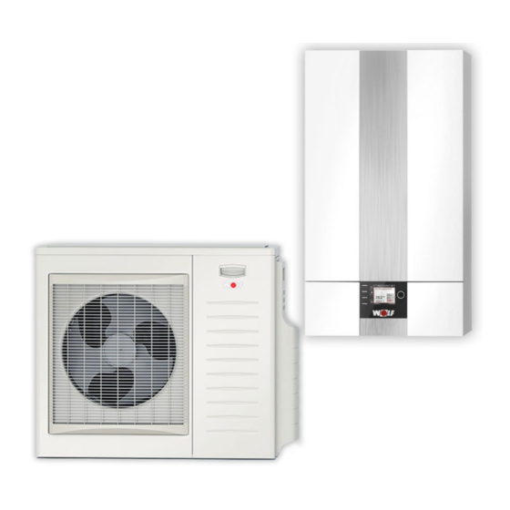
Installation and operating instructions
Split air/water heat pump
BWL-1 S(B)-07/10/14
From:
HCM-3 FW 1.30
AM
FW 1.40
Wolf GmbH • Postfach 1380 • D-84048 Mainburg • Tel. (+49) 8751/74-0 • Fax (+49) 8751/741600 • Internet: www.wolf-heiztechnik.de
Document no.: 3064298_201507
Integrated system log book
Subject to technical modifications
GB
Advertisement
Table of Contents

Related Manuals for Wolf BWL-1 S


Summary of Contents for Wolf BWL-1 S
- Page 1 Installation and operating instructions Split air/water heat pump Integrated system log book BWL-1 S(B)-07/10/14 From: HCM-3 FW 1.30 FW 1.40 Wolf GmbH • Postfach 1380 • D-84048 Mainburg • Tel. (+49) 8751/74-0 • Fax (+49) 8751/741600 • Internet: www.wolf-heiztechnik.de Document no.: 3064298_201507 Subject to technical modifications...
-
Page 2: Table Of Contents
Table of contents Contents ....................Page Information, layout and equipment 1. Safety information / standards and regulations ............5 2. General information ....................6 3. Information on the heat pump ................7-8 4. Standard delivery ......................9 5. Layout ......................... 10-11 6. Equipment features ....................12 7. - Page 3 Table of contents Contents ....................Page Control system modules 26. Display module / programming unit installation .............46 27. Programming unit BM-2 ..................47 28. AM display module ....................48 Operating the AM display module 29. Operating the AM display module .................49 29.1 Programming the quick start keys ..............49 Adjusting the set heating temperature ............49 Adjusting the set DHW temperature ............49 29.2 Boiler / status / messages ................50...
- Page 4 Table of contents Specification 32. Sound level ......................81 33. Configuring the dual mode point ................82 34. - 48. Heating output, el. power consumption, COP ..........83-97 49. Heating circuit residual head .................98 50. Specification ....................99-100 51. Sensor resistances ....................101 Commissioning 52. Commissioning ....................102 System log book 53. System log book ...................103-107 53.1 Responsibilities of the operator ..............103 53.1.1 Annual leak test ................103 53.1.2 Compulsory documentation ............104...
-
Page 5: Safety Information, Standards And Regulations
1. Safety information, standards and regulations Safety instructions The following symbols are used in this description to highlight important information concerning personal and operational safety: Denotes instructions with which you must strictly comply to prevent risk or injury to individuals, faults or damage to the appliance. Danger due to live electrical components. -
Page 6: General Information
When siting the heat pump, position and install it securely, to prevent it slipping or sliding during operation. The outdoor unit may only be installed outdoors. Only replace faulty components with original Wolf spare parts. Observe the specified electrical fuse ratings (see Specification). Any damage or loss resulting from technical modifications to Wolf control systems is excluded from our warranty. -
Page 7: Information On The Heat Pump
3. Information on the heat pump Application area The split air/water heat pump for heating water temperatures up to 55 °C and air temperatures down to -15 °C or -20 °C is designed exclusively for the heating of heating water and domestic hot water. The heat pump can be used in new or existing heating systems, taking into consideration the application limits (see "Specification"). - Page 8 DHW cylinders Wolf heat pumps require special DHW cylinders for heating the domestic hot water; these are available from the Wolf range of accessories. The indirect coil surface area in the DHW cylinders must be at least 0.25 m² per kW Please note of heating output.
-
Page 9: Standard Delivery
4. Standard delivery Standard delivery f Outdoor module, fully encased in box f Indoor module, fully encased in box containing the following: − Installation and operating instructions including system log book and maintenance instructions − Commissioning report with checklist − Suspension bracket and assembly set for indoor module −... -
Page 10: Layout
5. Layout Layout BWL-1S(B) indoor module AWO boiler water temperature Vent sensor for outdoor module controller (AWO T_boiler) Control electronics and power Condenser supply connection Electric booster heater (accessory for BWL-1SB) Heating circuit pressure sensor Refrigerant pressure sensor Pressure gauge High-efficiency heating circuit pump Heating circuit flow sensor (HC) Schrader valve... - Page 11 5. Layout Layout BWL-1S(B)-10/14 outdoor module Evaporator 4-way valve Electronic expansion valve Liquid separator Inverter compressor Layout BWL-1S(B)-07 outdoor module Evaporator 4-way valve Electronic expansion valve Liquid separator Inverter compressor 3064298_201507...
-
Page 12: Equipment Features
6. Equipment features BWL-1S(B) Indoor module • Demand-controlled electric booster heater for 2 / 4 / 6 kW depending on connection – Type BWL-1S For covering peak loads Adjustable for emergency mode or for screed drying Screed drying also possible without outdoor module •... -
Page 13: Dimensions Bwl-1S(B)
7. Dimensions BWL-1S(B) Indoor module Electrical connection 3064298_201507... - Page 14 7. Dimensions BWL-1S(B) BWL-1S(B)-07 outdoor module 1040 3064298_201507...
- Page 15 7. Dimensions BWL-1S(B) BWL-1S(B)-10 and BWL-1S(B)-14 outdoor module 3064298_201507...
-
Page 16: Siting Information / Minimum Room Volume
8. Siting the BWL-1S(B) Split air/water heat pump for Installation information: outdoor installation When selecting the installation site, observe the following points: - The heat pump must be accessible on all sides. The air intake should preferably be on a wall. - The air discharge side must be free from obstruction. - Page 17 8. Siting the BWL-1S(B) Transport to the installation site To prevent damage during transport, the heat pump must remain packaged and on its wooden pallet while being transported to the final installation site by pallet truck. Only transport the heat pump by pallet truck while packaged. Caution, risk of tipping. To prevent damage to the appliance, the heat pump's outdoor module must not be tilted more than 45°...
-
Page 18: Siting The Outdoor Module
9. Siting the outdoor module Minimum clearances for the outdoor module Fig.: Front view of outdoor module BWL-1S(B)-10/14 Fig.: Front view of outdoor module BWL-1S(B)-07 Air intake Air intake ≥ 100 ≥ 300 ≥ 100 ≥ 300 Air discharge Air discharge Fig.: Plan view of outdoor module BWL-1S(B)-10/14 Fig.: Plan view of outdoor module BWL-1S(B)-07 Air discharge a ≥ 1000 to obstacles obstructing the air discharge... -
Page 19: Siting The Indoor Module
10. Siting the indoor module Minimum clearances for the indoor module ≥ 40 ≥ 40 Fig.: Plan view of indoor module Fig.: Front view of indoor module Securing the appliance with the suspension bracket When installing the appliance, ensure that the fixings have sufficient load-bearing capacity. In addition, take into account the condition of the wall, otherwise refrigerant and water could escape, resulting in a risk of flooding. 1. Mark the Ø12 holes to be drilled for the suspension bracket, taking into account the minimum clearances. 2. Insert the rawl plugs and fit the suspension bracket using the bolts supplied. -
Page 20: Gravel Bed And Foundation Diagram For The Outdoor Module
11. Gravel bed and foundation diagram for the outdoor module Base for floorstanding installation > 650 BWL-1S(B)-07 220 mm 75 mm BWL-1S(B)-10/14 300 mm 155 mm A Gravel bed as condensate soakaway B Frost-protection base for foundation (compressed gravel, e.g. 0 – 32/56 mm), layer thickness in accordance with local conditions and applicable building regulations C Foundation strip D KG pipe DN 100 with 2 pipe bends 45°... -
Page 21: Anchoring The Outdoor Module And Providing Vibration Isolation
12. Anchoring the outdoor module and providing vibration isolation Tighten the nuts of the rubber mounts until approx. 8 mm of rubber becomes visible 8 mm Cast, level plinth of concrete with gravel base providing sufficient frost protection, cut-out for cable/line entry, see foundation diagram Secure in accordance with structural characteristics, Please note taking into account the appliance weight. -
Page 22: Wall Mounting The Outdoor Module
13. Wall mounting the outdoor module 8 mm Tighten the nuts of the rubber mounts until approx. 8 mm of rubber becomes visible Secure in accordance with structural characteristics, taking into account Please note the appliance weight. 3064298_201507... -
Page 23: Positioning The Wall Duct
14. Positioning the wall duct Wall duct above ground level Observe minimum distance from building wall Please note: The wall mounting support can only be used on walls with a high mass per unit area (> 250 kg/m²). Lightweight walls or stud walls are not permitted. -
Page 24: Routing The Refrigerant Lines
15. Routing the refrigerant lines The outdoor module is pre-filled with refrigerant R410A. No additional filling is required for lines up to 12 m in length. Minimum line length : 3 m Maximum line length : 25 m Max. height differential Indoor to outdoor unit : 15 m Line lengths between 12 and 25 m must be topped up with an additional 60 g/m refrigerant R410A. -
Page 25: Connecting The Refrigerant Lines To The Outdoor Module
Torque in Nm Liquid line Ø 10 mm 5/8 UNF 37 +/- 4 Hot gas line Ø 16 mm 7/8 UNF 70 +/- 7 Alternatively, the refrigerant lines can also be connected using the Euro flanged Euro flanged adaptor connection kit adapter connection kit for hard-soldering on refrigerant lines (available from the Wolf range of accessories). 3064298_201507... -
Page 26: Connecting The Refrigerant Lines Of The Indoor Module
Remove the nuts from the liquid line and hot gas line connections of the refrigerant lines. Slide the supplied nuts over the copper pipes. Flare the copper pipes. The Euro flanged adaptor connection kit, available from the Wolf range of accessories, can be used as an alternative to flaring. Do not allow any contaminants (e.g. metal swarf or moisture) to enter the Please note copper pipes. -
Page 27: Filling The Refrigerant Lines
No. 303/2008 Category I). Applicable standards and regulations and recognised engineering standards must be observed. Suitable personal protective equipment must be used when handling refrigerant. Refrigerant R410A used in WOLF split heat pumps is an air-displacing, non-toxic gas. Uncontrolled release of refrigerant may result in breathing difficulties and asphyxiation. Observe the corresponding regulations and guidelines for handling this refrigerant. -
Page 28: Filling The Refrigerant Lines
18. Filling the refrigerant lines Filling the indoor module and Single refrigerant line length < 12 m refrigerant lines The pre-filled quantity of refrigerant in the outdoor module is sufficient for a single line length of 3 to 12 m. Single refrigerant line length > 12 m Line lengths of 12 - 25 m must be topped up with an additional 60 g/m of refrigerant R410A. -
Page 29: Testing The Refrigerant Lines For Leaks
19. Testing the refrigerant lines for leaks Checking the refrigerant R 410A is an air-displacing, non-toxic gas. Uncontrolled release of refrigerant may result in breathing difficulties and asphyxiation. circuit for leaks Check the connections for refrigerant leaks: - All flared connections on the refrigerant lines between the indoor and outdoor unit. - All soldered joints and screw connections on the refrigerant lines in the indoor and outdoor unit. -
Page 30: Connecting The Heating/Cooling Circuit And The Dhw Circuit
20. Connecting the heating / cooling circuit and the DHW circuit Observe the following points for the heating circuit Connection for the vent hose Return, heating / DHW 28 x 1 Flow, heating 28 x 1 Hose, safety valve DN 25 Flow, DHW 28 x 1 Vent An air vent valve must be installed at the highest point on the system. - Page 31 Dirt trap To protect the heat pump, a dirt trap must be installed in the heating return. Installing dirt traps or carrying out any other modifications in the supply line to the safety valve is not permitted. Wolf recommends a sludge separator with magnetite separator to protect the appliance and the high-efficiency pump from dirt / sludge and magnetite. Dew point monitor (TPW) A dew point monitor (accessories) is required for surface cooling systems (e.g. underfloor heating circuit, cooling ceiling).
- Page 32 20. Connecting the heating / cooling circuit and the DHW circuit DHW cylinders - The DHW cylinder must be equipped with an internal indirect coil suitable for the heating output of the heat pump. - The internal indirect coil should have a surface area of at least 0.25m² per kW of heating output.
-
Page 33: Split Heating Centre With Cew-2-200
21. Split heating centre with CEW-2-200 Split heating centre The CEW-2-200 can be installed in combination with the BWL-1S-07/10/14 or with CEW-2-200 BWL-1SB-07/10/14 as a stacked heating centre. Split heating centre with CEW-2-200 Height of indoor module A mm Height of CEW-2-200 B mm 1290 Overall height... -
Page 34: Power Supply / General Information
22. Power supply / General information General information, The installation may only be carried out by an approved electrical contractor. Observe VDE regulations and all local regulations of your electrical connection power supply utility company. An omnipolar isolator with at least 3 mm contact separation must be integrated in the power cable upstream of the appliance. -
Page 35: Connection Diagram
23. Connection diagram Mains feed / connection Indoor module (IDU) Outdoor module (ODU) 230 V/50 Hz control AWO BUS 230 V/50 Hz electric heating 400 V/50 Hz electric heating On-site connections PSU, PV / Smart grid Indoor module Outdoor module BWL-1S(B)-07 BWL-1S(B)-07 230 V/50 HZ outdoor module... -
Page 36: Power Supply To The Outdoor Module
24. Power supply to the outdoor module BWL-1S(B)-07 BWL-1S(B)-10 Opening the casing BWL-1S(B)-14 Connecting the outdoor module * See "Specification" for fuse protection values BWL-1S(B)-07/230 V In terms of safe installation, the AWO BUS connection (43 V / 12 V) is not low voltage and must be routed together with the 230 V/400 V cable. -
Page 37: Power Supply To The Indoor Module
25. Power supply to the indoor module Opening / unhooking indoor module casing Opening the control unit cover Cable entry/ Cable entry fuse replacement Terminal strip X1 Contactor for electric heating Fuse F1 HCM-3 control PCB AWO communication PCB 3064298_201507... -
Page 38: Electric Heater Connection
25. Power supply to the indoor module 25.1 Electric heater connection Output 3WUV heating / DHW PSU, PV / Smart grid AWO BUS GTS (appliance type connector) * See "Specification" for fuse protection values 6/9 kW 4/6 kW 2/3 kW On the BWL-1S with integral 3-phase electric heating, the heater connection can be either single-phase, 2-phase or 3-phase . - Page 39 25. Power supply to the indoor module 25.2.1 Power-OFF The PSU can temporarily block the compressor or the electric heating by means of an external switch command (floating contact). The system's frost protection and operation of the heating circuit pump continue. Terminals X1 - 9 and 10 open Power-OFF active Terminals X1 - 9 and 10 bridged Power-OFF inactive Note: If the power supply is without power-OFF, insert a bridge.
-
Page 40: Control Pcb Connection
25. Power supply to the indoor module 25.3 HCM-3 control PCB connection Fig: HCM-3 control PCB eBus 1(+), 2(-) Wolf control accessories T_DHW (5kNTC cylinder sensor) T_outside (5kNTC outside temperature sensor) E2/SAF (5kNTC header sensor SAF; alternatively 0-10V- switching by e.g. BMS) - Page 41 25. Power supply to the indoor module 230 V mains connection The control and safety equipment is fully wired and tested. You only need to connect the power supply and the external accessories. Create a permanent connection for the power supply. Provide the power supply via a mains isolator (e.g.
- Page 42 25. Power supply to the indoor module Connection, HCP (230 V AC; max. 1.5 A) * Push connecting cable through cable entry. Connect the connecting cable to terminals L1, N and * M ax. 1.5 A / 345 VA per output, sum of all outputs no more than 600 VA Fig: HCP connection Connection, 3WUV heating / cooling (230 V AC;...
- Page 43 Fig: Cylinder sensor (SF) connection Connection, digital Wolf control accessories (e.g. BM-2, MM, KM, SM1, SM2) Only connect control units from the Wolf accessory range. Each accessory is supplied with its own connection diagram. Use a two-core cable (cross-section > 0.5 mm²) as the connecting cable between the control unit accessory and the BWL-1S (1 is + and 2 is -).
-
Page 44: Wiring Diagram For Hcm-3 / Awo
25. Power supply to the indoor module 25.4 Wiring diagram, HCM-3 control PCB, indoor module Heating/cooling Control feed eBUS E2/SAF Netz Electric heater 3064298_201507... - Page 45 25. Power supply to the indoor module Wiring diagram, AWO communication PCB, indoor module 3064298_201507...
-
Page 46: Display Module / Programming Unit Installation
Please note: flow temperature control • Use when BM2 is used as a remote control or • Time program for heating, DHW and DHW circulation in a cascade circuit • AM is always in the heating appliance Plug the AM display module into the slot above the ON/OFF switch (Wolf logo). Switch on power supply / MCB and switch ON/OFF switch to ON. 3064298_201507... -
Page 47: Programming Unit Bm-2
27. BM-2 programming unit BM-2 overview Note: Other functions and descriptions can be found in the installation instructions for contractors or the user operating instructions for the BM-2 programming unit. Operating mode Page heading Quick start keys BM-2 status display HP status Key 1 Heating appliance... -
Page 48: Am Display Module
28. AM display module AM overview Note: Other functions and descriptions can be found in the installation instructions for contractors or the user operating instructions for the AM display module. Page heading Quick start keys Key 1 Heating appliance Boiler temperature Key 2 Rotary selector with 38.0 °C... -
Page 49: Operating The Am Display Module
29. Operating the AM display module 29.1 Programming the quick start keys Press the quick start key you wish to program, turn the rotary selector to indicate the desired set temperature, then press the rotary selector to confirm. Set temperature, heating Key 1 (if BM-2 as remote control - no function) Set temperature, DHW Key 2 (if BM-2 as remote control - no function) -
Page 50: Boiler / Status / Messages
29. Operating the AM display module 29.2 Heating appliance / status / message Heating appliance Flow temperature Heating appliance System pressure Boiler temperature Turn 38.0 °C System pressure 1.5 bar Status Operating mode Status HP status Turn Operating mode Standby HP status Standby Notification... -
Page 51: Heat Pump Operating Mode
29. Operating the AM display module 29.2.1 Heat pump operating mode Display shows Meaning ODU test Outdoor unit test Test Relay test active (IDU) Antifreeze HC Heat pump frost protection function, heating circuit temperature below frost protection limit (T_boiler, T_return, T_header) Antifreeze DHW Heat pump frost protection function, DHW cylinder temperature below frost protection limit... -
Page 52: System Data Displays (Menu Structure)
29. Operating the AM display module 29.3 Displays (system data) Main menu back Displays Default settings Contractor back Displays back Displays T_boiler T_Boiler set T_outside 14.4 °C HC pressure - - - - - - - - - - - - - - - - - - - - - - - - T_outside T_return T_return... -
Page 53: Default Settings / Setting Options (Menu Structure)
29. Operating the AM display module 29.4 Default settings / Setting options Main menu back Displays Default settings Contractor back Default settings back Language Default set. Key lock ← back DHW operating mode Language Key lock DHW quick heat-up DHW op mode ←... -
Page 54: Key Lock
29. Operating the AM display module 29.4.2 In the Key lock submenu, the key lock can be switched On or Off The key lock prevents unintentional adjustment of the heating system (e.g. by children or when cleaning). When the key lock is switched on, it is automatically activated for the rotary selector with push-button function one minute after the last setting. -
Page 55: Dhw Quick Heat-Up
29. Operating the AM display module 29.4.4 DHW quick heat-up Setting range: Off, On Factory setting: Off If this parameter is set, the DHW temperature is controlled once to the set value using all available heat sources. The parameter is then automatically reset. Main menu Submenu Menu item... -
Page 56: Heating Contractor (Menu Structure)
29. Operating the AM display module 29.5 heating contractor (menu structure) Main menu back Displays Default settings Contractor back Contractor System Relay test Contractor code 1111 back back back Enabling On / Off Relay test parallel mode Off / On On / Off System back... -
Page 57: Contractor Level Password
30. Contractor level password Password for contractor level To access the contractor level, enter the password 1111 with the rotary selector to obtain authorisation. (AM display module) After authorisation, open the "Contractor" menu item. Main menu Code entry Main menu Password Authorisation ← back... -
Page 58: Contractor Level
31. Contractor level 31. Contractor level overview The contractor level serves to set system-specific parameters f Test 31.1 Relay test 31.2 System 31.3 Parameters 31.4 Parameter reset 31.5 Special 31.6 IDU service 31.7 ODU service 31.8 Fault history 31.9 Deleting the fault history 31.10 Acknowledging faults 31.1 Relay test Under the menu item Contractor, turn and press the controller to access the "Relay test"... -
Page 59: Parameters
31. Contractor level 31.3 Parameters Under the menu item Contractor, turn and press the controller to access the "Parameters" submenu. Here, the contractor can change the system's factory settings. Incorrect settings may result in malfunctions and damage to the system. Also observe the information / settings in the installation instructions "AM display module for the contractor". -
Page 60: Overview Of Contractor Parameters
31. Contractor level 31.3.1 Overview of contractor parameters for split heat pump: Contractor Meaning Setting range Factory setting Individual setting parameter System WP001 System configuration 01, 02, 05, 11, 12, 14, 15, 33, 34, 51, 52 WP002 Function input 1 (E1) none none RT/DHW... - Page 61 31. Contractor level Contractor Meaning Setting range Factory setting Individual setting parameter Compressor WP080 BWL-1S(B)-07 dual mode point, -20.0 °C ... 45.0 °C -15.0 °C compressor WP080 BWL-1S(B)-10/14 dual mode point, compressor -20.0 °C ... 45.0 °C -20.0 °C Electric heater, add. ht. gen. WP090 Enable electric heating for heating mode Off, On...
-
Page 62: Description Of Contractor Parameters
31. Contractor level 31.3.2 Description of contractor parameters Contractor Description parameter WP001 For setting a pre-configured system version subject to heat pump design and application (see "Overview of system configurations"). WP002 For optionally assigning one of the following functions to programmable input E1: Code Function input E1 None No function Heating block (room thermostat) Contact open - blocked Contact closed - heating mode enabled DHW block Contact open - blocked... - Page 63 31. Contractor level Contractor Description parameter WP003 For optionally assigning one of the following functions to programmable input E1: Code Function output A1 None No function Timer20 DHW circulation pump activation 20 % (2 mins on, 8 mins off) Timer50 DHW circulation pump activation 50 % (5 mins on, 5 mins off) Timer100 DHW circulation pump activation 100 % (continuous operation)
- Page 64 31. Contractor level Contractor Description parameter WP015 WP016=On: For setting the maximum speed of the feed/heating circuit pump (ZHP). WP016=Off: For setting the constant speed of the feed/heating circuit pump (ZHP). WP016 Enables spread control (controlling to set spread WP010) and PWM actuation (WP015) of the feed/heating circuit pump (ZHP). WP017 For setting the max. flow temperature limit (T_boiler). With screed drying function for setting the maximum temperature. WP018 For setting the min. flow temperature limit (T_boiler). With screed drying function for setting the constant temperature. WP020 For setting the hysteresis value for DHW heating or DHW cylinder heating.
-
Page 65: Overview Of System Configurations
The entire system must be restarted (power off / power on) each time a change is made to the configuration. Note: Hydraulic diagrams and electrical details can be found on the Wolf homepage and in the "Hydraulic System Solutions" technical guide. 3064298_201507... -
Page 66: System Configurations
System configuration 01 BWL-1S(B) ● Split air/water heat pump ● Cylinder in series ● One heating circuit ● DHW heating ● Active cooling possible (in conjunction with an additional 3-way diverter valve for cooling) Heating circuit DHW cylinder Cylinder in series Indoor module Outdoor module In conjunction with active cooling... - Page 67 System configuration 02 BWL-1S(B) ● Split air/water heat pump ● Cylinder in series ● Extension, circuit with mixer, with MM ● DHW heating ● Solar DHW cylinder ● Solar circuit extension with SM1 Extension options Circuit with mixer MaxTh Solar circuit SColS Solar DHW cylinder Cylinder in series SCylS...
- Page 68 System configuration 05 BWL-1S(B) ● Split air/water heat pump ● Cylinder in series ● One heating circuit ● DHW heating ● Solar DHW cylinder ● Solar circuit extension with SM1 ● Active cooling possible In conjunction with active cooling Important information: In this schematic diagram, shut-off valves, air vent valves and safety equipment are not fully represented. These should be provided for each individual system, in line with the applicable standards and regulations.
- Page 69 System configuration 11 BWL-1S(B) ● Split air/water heat pump ● Separating cylinder ● One heating circuit ● DHW heating Heating circuit DHW cylinder Separating cylinder Please note: Header temperature sensor HTS must be installed in the return area of the low loss Indoor module header or separating cylinder.
- Page 70 System configuration 12 BWL-1S(B) ● Split air/water heat pump ● BSP-W ● BVG-Lambda ● Extension, circuit with mixer, with MM ● Solar circuit extension with SM1 ● DHW heating Important information: In this schematic diagram, shut-off valves, air vent valves and safety equipment are not fully represented. These should be provided for each individual system, in line with the applicable standards and regulations.
- Page 71 System configuration 12 BWL-1S(B) ● Split air/water heat pump ● BSH-800/1000 ● BVG-Lambda ● Extension, circuit with mixer, with MM ● Solar circuit extension with SM1 ● DHW heating Important information: In this schematic diagram, shut-off valves, air vent valves and safety equipment are not fully represented. These should be provided for each individual system, in line with the applicable standards and regulations.
- Page 72 System configuration 14 BWL-1S(B) ● Split air/water heat pump ● BSP-W ● BVG-Lambda ● Extension, circuit with mixer, with MM ● Solar circuit extension with SM1 ● DHW heating ● Active cooling possible Important information: In this schematic diagram, shut-off valves, air vent valves and safety equipment are not fully represented. These should be provided for each individual system, in line with the applicable standards and regulations.
- Page 73 System configuration 15 BWL-1S(B) ● Split air/water heat pump ● Separating cylinder ● Solar DHW cylinder ● Heating circuit ● Extension, circuit with mixer, with MM ● Solar circuit extension with SM1 ● DHW heating ● Active cooling with direct heating circuit possible Important information: In this schematic diagram, shut-off valves, air vent valves and safety equipment are not fully represented. These should be provided for each individual system, in line with the applicable standards and regulations.
- Page 74 System configuration 33 3064298_201507...
- Page 75 System configuration 34 BWL-1S(B) ● Split air/water heat pump ● BSH-800/1000 ● TOB ● Extension, circuit with mixer, with MM ● Solar circuit extension with SM1 ● DHW heating ● Alternatively, dual mode operation only is possible Important information: In this schematic diagram, shut-off valves, air vent valves and safety equipment are not fully represented. These should be provided for each individual system, in line with the applicable standards and regulations.
- Page 76 System configuration 51 External demand / control by U = 0…10 V at input E2/SAF: building management system BMS 0 V ≤ < 1.2 V → heat pump OFF 1.2 V ≤ ≤ 4.0 V → 0-100 % compressor cooling mode 4.2 V ≤ ≤ 7.0 V → 0-100 % compressor heating mode 7.2 V ≤ ≤ 10.0 V → 0-100 % electric heating heating mode Notes: - Connect the outside temperature sensor OTS...
-
Page 77: System Configurations
System configuration 52 External demand / control by External floating contact at input E2/SAF: building management system BMS Open → Heat pump OFF Closed → Compressor ON Notes: - Connect the outside temperature sensor OTS - The electric heating is not activated (except for frost protection) - Program WP003 for defrost →... -
Page 78: Parameter Reset
31. Contractor level 31.4 Parameter reset If a parameter reset is carried out, all settings and statistical data are reset to factory settings. See Parameter settings Main menu Submenu Menu item Contractor Reset ← back parameters to Relay test factory settings? Chapter System Password for contractor level... -
Page 79: Odu Service (Outdoor Unit)
31. Contractor level 31.7 ODU service The ODU service allows you to call up the process values for the outdoor module. Main menu Submenu Menu item Contractor ODU service ← back Mod. level Special Comp. freq. Chapter IDU service Fan speed Password for contractor level ODU service T evap. -
Page 80: Deleting The Fault History
31. Contractor level 31.9 Deleting the fault history If the "Delete fault history" parameter is performed, all data is deleted. Main menu Submenu Menu item Contractor Reset Special fault history? IDU service Chapter ODU service Password for contractor level Fault history Delete fault history ←... -
Page 81: Sound Level
32. Sound level Sound level Noise levels must be taken into consideration when siting the system. In accordance with TA-Lärm [or local regulations], the following emission limits must be observed: Area Emission limits [dB(A)] Daytime Night 6.00 - 22.00 h 22.00 - 6.00 h Spa complexes, hospitals and care homes, where indicated as such by means of signs on the premises or road. -
Page 82: Configuring The Dual Mode Point
33. Configuring the dual mode point Configuration example Central heating demand (building heat load) to DIN 4701 or EN 12831 of 7.7 kW. A DHW demand for 4 people (0.25 kW/person) and a standard outside temperature of -16 °C are assumed. The power supply utility specifies a blocking time of 2 x 2 hours. The blocking time factor Z is 1.1. Using these figures, the required heat pump output is calculated as follows: = (Q ) x Z (7.7 kW + 1.0 kW) x 1.1 = 9.6 kW 9.6 kW - 5.6 kW = 4.0 kW... -
Page 83: 48. Heating Output, El. Power Consumption, Cop
34. Heating output, el. power consumption, COP - BWL-1S(B)-07/230 V, flow 35 °C Heating output to EN 14511 BWL-1S-07: Heizleistung bei Vorlauf 35° Air inlet temperature [°C] minimal nominal maximal minimal nominal maximal Electric power consumption in steady state BWL-1S-07: el. Leistungsaufnahme bei Vorlauf 35° Air inlet temperature [°C] minimal nominal maximal... - Page 84 35. Heating output, el. power consumption, COP - BWL-1S(B)-07/230 V, flow 45 °C Heating output to EN 14511 BWL-1S-07: Heizleistung bei Vorlauf 45° Air inlet temperature [°C] minimal nominal maximal minimal nominal maximal Electric power consumption in steady state BWL-1S-07: el. Leistungsaufnahme bei Vorlauf 45° Air inlet temperature [°C] minimal nominal maximal...
- Page 85 36. Heating output, el. power consumption, COP - BWL-1S(B)-07/230 V, flow 55 °C Heating output to EN 14511 BWL-1S-07: Heizleistung bei Vorlauf 55° Air inlet temperature [°C] minimal nominal maximal minimal nominal maximal Electric power consumption in steady state BWL-1S-07: el. Leistungsaufnahme bei Vorlauf 55° Air inlet temperature [°C] minimal nominal maximal...
- Page 86 37. Heating output, el. power consumption, COP - BWL-1S(B)-10/400 V, flow 35 °C Heating output to EN 14511 BWL-1S-10: Heizleistung bei Vorlauf 35° Air inlet temperature [°C] minimal nominal maximal minimal nominal maximal Electric power consumption in steady state BWL-1S-10: el. Leistungsaufnahme bei Vorlauf 35° Air inlet temperature [°C] minimal nominal maximal...
- Page 87 38. Heating output, el. power consumption, COP - BWL-1S(B)-10/400 V, flow 45 °C Heating output to EN 14511 BWL-1S-10: Heizleistung bei Vorlauf 45° Air inlet temperature [°C] minimal nominal maximal minimal nominal maximal Electric power consumption in steady state BWL-1S-10: el. Leistungsaufnahme bei Vorlauf 45° Air inlet temperature [°C] minimal nominal maximal...
- Page 88 39. Heating output, el. power consumption, COP - BWL-1S(B)-10/400 V, flow 55 °C Heating output to EN 14511 BWL-1S-10: Heizleistung bei Vorlauf 55° Air inlet temperature [°C] minimal nominal maximal minimal nominal maximal Electric power consumption in steady state BWL-1S-10: el. Leistungsaufnahme bei Vorlauf 55° Air inlet temperature [°C] minimal nominal maximal...
- Page 89 40. Heating output, el. power consumption, COP - BWL-1S(B)-14/400 V, flow 35 °C Heating output to EN 14511 BWL-1S-14: Heizleistung bei Vorlauf 35° Air inlet temperature [°C] minimal nominal maximal minimal nominal maximal Electric power consumption in steady state BWL-1S-14: el. Leistungsaufnahme bei Vorlauf 35° Air inlet temperature [°C] minimal nominal maximal...
- Page 90 41. Heating output, el. power consumption, COP - BWL-1S(B)-14/400 V, flow 45 °C Heating output to EN 14511 BWL-1S-14: Heizleistung bei Vorlauf 45° Air inlet temperature [°C] minimal nominal maximal minimal nominal maximal Electric power consumption in steady state BWL-1S-14: el. Leistungsaufnahme bei Vorlauf 45° Air inlet temperature [°C] minimal nominal maximal...
- Page 91 42. Heating output, el. power consumption, COP - BWL-1S(B)-14/400 V, flow 55 °C Heating output to EN 14511 BWL-1S-14: Heizleistung bei Vorlauf 55° Air inlet temperature [°C] minimal nominal maximal minimal nominal maximal Electric power consumption in steady state BWL-1S-14: el. Leistungsaufnahme bei Vorlauf 55° Air inlet temperature [°C] minimal minimal nominal...
- Page 92 43. Heating output, el. power consumption, COP - BWL-1S(B)-10/230 V, flow 35 °C Heating output to EN 14511 BWL-1SB-10: Heizleistung bei Vorlauf 35° Air inlet temperature [°C] minimal nominal maximal minimal nominal maximal Electric power consumption in steady state BWL-1SB-10: el. Leistungsaufnahme bei Vorlauf 35° Air inlet temperature [°C] minimal nominal maximal...
- Page 93 44. Heating output, el. power consumption, COP - BWL-1S(B)-10/230 V, flow 45 °C Heating output to EN 14511 BWL-1SB-10: Heizleistung bei Vorlauf 45° Air inlet temperature [°C] minimal nominal maximal minimal nominal maximal Electric power consumption in steady state BWL-1SB-10: el. Leistungsaufnahme bei Vorlauf 45° Air inlet temperature [°C] minimal nominal maximal...
- Page 94 45. Heating output, el. power consumption, COP - BWL-1S(B)-10/230 V, flow 55 °C Heating output to EN 14511 BWL-1SB-10: Heizleistung bei Vorlauf 55° Air inlet temperature [°C] minimal nominal maximal minimal nominal maximal Electric power consumption in steady state BWL-1SB-10: el. Leistungsaufnahme bei Vorlauf 55° Air inlet temperature [°C] minimal nominal maximal...
- Page 95 46. Heating output, el. power consumption, COP - BWL-1S(B)-14/230 V, flow 35 °C Heating output to EN 14511 BWL-1SB-14: Heizleistung bei Vorlauf 35° Air inlet temperature [°C] minimal nominal maximal minimal nominal maximal Electric power consumption in steady state BWL-1SB-14: el. Leistungsaufnahme bei Vorlauf 35° Air inlet temperature [°C] minimal minimal nominal...
- Page 96 47. Heating output, el. power consumption, COP - BWL-1S(B)-14/230 V, flow 45 °C Heating output to EN 14511 BWL-1SB-14: Heizleistung bei Vorlauf 45° Air inlet temperature [°C] minimal nominal maximal minimal nominal maximal Electric power consumption in steady state BWL-1SB-14: el. Leistungsaufnahme bei Vorlauf 45° Air inlet temperature [°C] minimal nominal maximal...
-
Page 97: Heating Output, El. Power Consumption, Cop
48. Heating output, el. power consumption, COP - BWL-1S(B)-14/230 V, flow 55 °C Heating output to EN 14511 BWL-1SB-14: Heizleistung bei Vorlauf 55° Air inlet temperature [°C] minimal nominal maximal minimal nominal maximal Electric power consumption in steady state BWL-1SB-14: el. Leistungsaufnahme bei Vorlauf 55° Air inlet temperature [°C] minimal nominal maximal... -
Page 98: Heating Circuit Residual Head
49. Heating circuit residual head Heating circuit residual head BWL-1S(B)-14 BWL-1S(B)-10 BWL-1S(B)-07 Flow rate [l/min] Residual head / nominal water flow rate BWL- BWL-1S(B)-10 / BWL-1S(B)-14 / 1S(B)-07 400V 400V Water flow rate, l/min 19.7 28.8 34.1 nominal (5K) Residual head mbar BWL-1S(B)-10 / BWL-1S(B)-14 / 230 V 230 V Water flow rate, l/min... -
Page 99: Specification
50. Specification TYPE BWL-1S(B) - 07/230 V BWL-1S(B) - 10/400 V BWL-1S(B) - 14/400 V Width x height x depth of outdoor unit 1040 x 865 x 340 900 x1255 x 340 900 x1255 x 340 (incl. feet, incl. front doors) Width x height x depth of indoor unit 440 x 790 x 340 440 x 790 x 340... - Page 100 50. Specification TYPE BWL-1S(B) - 10/230 V BWL-1S(B) - 14/230 V Width x height x depth of outdoor unit 900 x1255 x 340 900 x1255 x 340 (incl. feet, incl. front doors) Width x height x depth of indoor unit 440 x 790 x 340 440 x 790 x 340 (incl.
-
Page 101: Sensor Resistances
51. Sensor resistances Outside temperature (OT), return temperature (RT), header temperature (HT), flow temperature sensor resistances (FL, T_boiler), flow temperature of mixer circuit (FS), DHW cylinder temperature (CS) Temp. Resist. Temp. Resist. Temp. Resist. Temp. Resist. °C °C °C °C 51393 8233 1870 48487 7857 1800 45762 7501 1733 43207 7162 1669 40810 6841 1608 38560 6536 1549 36447 6247 1493 34463 5972 1438... -
Page 102: Commissioning
52. Commissioning Commissioning To ensure correct operation, we recommend that the system is commissioned by our customer service department. A commissioning report with checklist is supplied with every appliance and should be worked through before commissioning. The key criteria are: - Has the appliance been positioned and installed in line with the installation instructions? - Have all electrical and hydraulic connections been completed in full? - Are all slides and shut-off valves in the heating water circuit open? -
Page 103: System Log Book
Wolf split heat pumps use F-gas R410A, an HFC mixture with a global warming potential (GWP100) of 2088. This means that 1 kg of R410A equates to 2.088 t of CO2. Which Wolf split heat pumps require a leak test is detailed in the following table. BWL-1S(B)-07 BWL-1S(B)-10... -
Page 104: Compulsory Documentation
53. System log book 53.1.2 All work carried out on a heat pump, e.g. maintenance, repair and leak tests, must be Compulsory documentation documented and the record of results must be retained for five years. This obligation applies to the operator and the company carrying out the work. The following data must be entered: f Details of all repair and maintenance work f Type of refrigerant filled into the system (new, re-used or recycled) and the quantity of refrigerant removed from the system... -
Page 105: System Data
Postal address _____________________________________________________________ Installation room _____________________________________________________________ Tel. no. of system operator Wolf heat pump type: ___________________________________________ Serial number _________________________________________________ Year of construction ____________________________________________ Commissioning ________________________________________________ Refrigerant/weight ______________________________________________ The above data can be found on the type plate of the appliance. - Page 106 53. System log book The following maintenance work and regulatory leak tests (to para 5, section 3 of the Chemicals Climate Protection Ordinance in conjunction with regulation (EC) no. 303/2008 - Category I) have been carried out on the heat pump's refrigerant circuit: Date - Results of maintenance...
- Page 107 53. System log book The following maintenance work and regulatory leak tests (to para 5, section 3 of the Chemicals Climate Protection Ordinance in conjunction with regulation (EC) no. 303/2008 - Category I) have been carried out on the heat pump's refrigerant circuit: Date - Results of maintenance...
-
Page 108: Maintenance / Cleaning
54. Maintenance / cleaning Although heat pumps are considered low-maintenance heating systems, regular periodic maintenance work offers advantages. • Operational reliability is maintained. • A consistently high seasonal performance factor is achieved. • Low fault rate. • The service life of system components can be prolonged. • Possible damage or faults are detected early. • Heating convenience is assured in the long-term. • Legal requirements are met. Overview of maintenance work Cleaning BWL-1S(B) Completed Clean dirt filter in heating circuit Clean heat pump casing and interior Clean fins on evaporator of air heat pump Clean condensate pan... - Page 109 54. Maintenance / cleaning Cleaning the evaporator on the BWL-1S(B) In areas with high concentrations of dust or pollen, shorter cleaning intervals Please note may be necessary alongside the mandatory annual inspection and cleaning, in order to ensure that the system operates efficiently. Adjust the cleaning interval to suit the local conditions. The evaporator must be checked annually for dirt/contamination and cleaned if necessary.
-
Page 110: Troubleshooting
Never remove, bypass or otherwise disable any safety or monitoring equipment. Only operate the heat pump in perfect technical condition. Any faults or damage which impact or might impact upon safety must be remedied immediately by a qualified contractor. Only replace faulty components and equipment with original Wolf spare parts. Faults are shown in plain text on the display of the control accessory – AM display module or BM-2 programming unit – and correspond to the messages listed in the following tables. - Page 111 55. Troubleshooting Fault Short designation Possible cause Remedy code Boiler sens. faulty Flow temperature (T_boiler) outside Check flow temperature (T_boiler) permissible range (0 … 95 °C) Cable to sensor is faulty Check cable and plug-in connection Sensor faulty Check / replace sensor DHW sensor faulty DHW cylinder temperature outside Check DHW cylinder temperature permissible range (0 …...
- Page 112 55. Troubleshooting Fault Short designation Possible cause Remedy code Low pressure Low pressure fault (ODU) Contact service engineer (refrigerant circuit / intake gas side) High pressure High pressure fault (ODU) Contact service engineer (refrigerant circuit / hot gas side) T_intake gas Refrigerant temperature outside permissible Check cable and plug-in connection (AWO)
-
Page 113: Abbreviations / Key
56. Abbreviations / key Abbreviations / key 0-10V/On-Off - Input for external demand 3way div vlv htg/clg - 3-way diverter valve for heating/cooling 3way div vlv htg/ - 3-way diverter valve for heating/DHW - Programmable output 1 - Outside temperature sensor - Indoor module printed circuit board - Appliance type connector BM-2... -
Page 114: Product Fiche According To Regulation (Eu) No. 811/2013
Annual energy consumption under colder clima- 4,287 6,120 6,848 4,287 te conditions Annual energy consumption under warmer 1,687 2,119 4,244 1,687 climate conditions Sound power level, outdoors 3064298_201507 Wolf GmbH, Postfach 1380, D-84048 Mainburg, Tel. +49-8751/74-0, Fax +49-8751/741600, Internet: www.wolf-heiztechnik.de Material number: 3021352 03/2015... - Page 115 Annual energy consumption under colder clima- 6,120 6,848 te conditions Annual energy consumption under warmer 3,061 2,119 3,061 4,244 climate conditions Sound power level, outdoors 3064298_201507 Wolf GmbH, Postfach 1380, D-84048 Mainburg, Tel. +49-8751/74-0, Fax +49-8751/741600, Internet: www.wolf-heiztechnik.de Material number: 3021352 03/2015...
- Page 116 Annual energy consumption under colder clima- 5213 9125 7439 5313 te conditions Annual energy consumption under warmer 2717 2862 3765 2717 climate conditions Sound power level, outdoors 3064298_201507 Wolf GmbH, Postfach 1380, D-84048 Mainburg, Tel. +49-8751/74-0, Fax +49-8751/741600, Internet: www.wolf-heiztechnik.de Material number: 3020915 03/2015...
- Page 117 Annual energy consumption under colder clima- 9125 7439 te conditions Annual energy consumption under warmer 3904 2862 5083 3765 climate conditions Sound power level, outdoors 3064298_201507 Wolf GmbH, Postfach 1380, D-84048 Mainburg, Tel. +49-8751/74-0, Fax +49-8751/741600, Internet: www.wolf-heiztechnik.de Material number: 3020915 03/2015...
-
Page 118: Technical Parameters According To Eu Regulation No. 813/2013
Rated air flow rate, outdoors For water-/brine-to-water heat m3/h pumps: Rated brine or water flow rate Contact details Wolf GmbH, Industriestraße 1, D-84048 Mainburg (*) For heat pump space heaters and heat pump combination heaters, the rated heat output P is equal to the design load for heating P , and the rated heat output of a supplementary rated designh heater P is equal to the supplementary capacity for heating sup(Tj). -
Page 119: Declaration Of Conformity
DECLARATION OF CONFORMITY (to DIN EN ISO/DIN 17050-1) Number: 3064298 Wolf GmbH Issued by: Address: Industriestrasse 1, D-84048 Mainburg Product: Split - air/water heat pump BWL-1S(B)-07/230V BWL-1S(B)-10/400V BWL-1S(B)-14/400V BWL-1S(B)-10/230V BWL-1S(B)-14/230V The product described above conforms to the requirements specified in the following documents: DIN EN 349 DIN EN 378 DIN EN ISO 12100... - Page 120 Wolf GmbH Postfach 1380 • D-84048 Mainburg • Tel. +49-8751/74-0 • Fax +49-8751/741600 Internet: www.wolf-heiztechnik.de BWL-1S(B) installation and operating instructions Subject to technical modifications...
Need help?
Do you have a question about the BWL-1 S and is the answer not in the manual?
Questions and answers