Sign In
Upload
Download
Table of Contents
Contents
Add to my manuals
Delete from my manuals
Share
URL of this page:
HTML Link:
Bookmark this page
Add
Manual will be automatically added to "My Manuals"
Print this page
×
Bookmark added
×
Added to my manuals
Manuals
Brands
Power Probe Manuals
Measuring Instruments
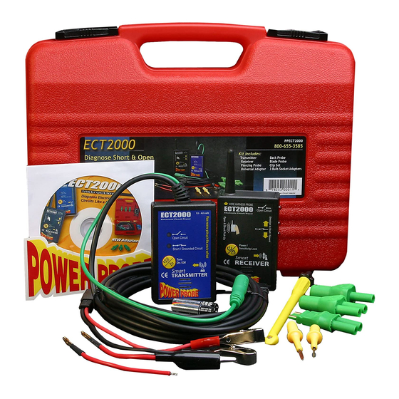
power probe III ECT-2000
Instruction manual
Power Probe ECT 2000 Instruction Manual
Professional electrical tester
Hide thumbs
Also See for ECT 2000
:
Instruction manual
(28 pages)
1
2
Table Of Contents
3
4
5
6
7
8
9
10
11
12
13
14
15
16
17
18
19
20
21
22
23
page
of
23
Go
/
23
Contents
Table of Contents
Bookmarks
Table of Contents
Table of Contents
Power Probe I & II Instructions
Hook-Up and Quick Self-Test
Conexiones y Auto Prueba Rápida
Polarity Testing
Probando Polaridades
Continuity Testing
Prueba de Continuidad
Activating Components out of Vehicle's Electrical System
Activando Componentes Fuera del Circuito del Vehículo
Testing Trailer Lights and Connections
Probando Luces y Conexiones de Trailers
Activating Electrical Components with Positive (+) Voltage
Activando Componentes Eléctricos con Positivo (+) Voltaje
Activating Electrical Components with Negative (-) Voltage
Activando Componentes Eléctricos con Negativo (-) Tierra
Jumper Lead Feature
Función de Puente
Checking for Bad Ground Contacts
Following and Locating Short Circuits
Verificando por Malos Contactos de Masa/Tierra
Siguiendo y Ubicando Corto Circuitos
Using the Light and Tone (Power Probe II)
Usando la Luz el Tono ( Power Probe II )
Parts and Accessories for Your Power Probe
Repuestos y Assesorios para Su Power Probe
SMART" ECT 2000 Instructions
The "SMART" Transmitter
Connecting the "SMART Transmitter
The "SMART" Receiver
Locking the Reception Distance
Tracing Short Circuits
Tracing Open Circuits
Circuit Wiggle & Flex Test
Power Probe Warranty
Power Probe Garantía
Advertisement
Quick Links
1
Table of Contents
2
Hook-Up and Quick Self-Test
3
Power Probe I & II Instructions
4
Following and Locating Short Circuits
5
Smart Ect 2000 Instructions
6
Tracing Open Circuits
Download this manual
Instructions
for ECT and
Power Probe
www.powerprobe.com
Table of
Contents
Previous
Page
Next
Page
1
2
3
4
5
Advertisement
Table of Contents
Need help?
Do you have a question about the ECT 2000 and is the answer not in the manual?
Ask a question
Questions and answers
Related Manuals for Power Probe ECT 2000
Measuring Instruments Power Probe Power Probe III Instruction Manual
(28 pages)
Measuring Instruments Power Probe ETDPPDCM80 User Manual
Amp clamp (80 pages)
Measuring Instruments Power Probe BASIC Instruction Manual
(30 pages)
Measuring Instruments Power Probe IV User Manual
(28 pages)
Measuring Instruments Power Probe 3EZ Manual
(56 pages)
Measuring Instruments Power Probe PPDRAW User Manual
(33 pages)
Measuring Instruments Power Probe PPDCM80 User Manual
Amp clamp (80 pages)
This manual is also suitable for:
Power probe i
Power probe ii
Table of Contents
Save PDF
Print
Rename the bookmark
Delete bookmark?
Delete from my manuals?
Login
Sign In
OR
Sign in with Facebook
Sign in with Google
Upload manual
Upload from disk
Upload from URL


Need help?
Do you have a question about the ECT 2000 and is the answer not in the manual?
Questions and answers