Chapters
Table of Contents

Subscribe to Our Youtube Channel
Related Manuals for Power Probe BASIC


Summary of Contents for Power Probe BASIC
- Page 1 Power Probe Basic Power Probe Basic Power Probe Basic Instruction Manual English Manual de Instrucciones Español The Ultimate in Circuit Testing www.powerprobe.com • 800-655-3585 www.powerprobe.com...
-
Page 2: Table Of Contents
POSITIVE (+) VOLTAGE ............12 GROUND SWITCHING A CIRCUIT HAVING AN ELECTRICAL LOAD ..............13 REPLACING OLD ROCKER SWITCH ........14 ATTACHING THE SWITCH LATCH ..........14 FOLLOWING AND LOCATING SHORT CIRCUITS ....15 POWER PROBE WARRANTY ............. 15 www.powerprobe.com • 800-655-3585... -
Page 3: Introduction
Power Probe Basic INTRODUCTION Thank you for purchasing the Power Probe Basic. It’s your best value for testing automotive electrical problems. After connecting it to the vehicle’s battery you can now see if a circuit is Positive, Negative or Open by probing it and observing the RED or GREEN LED. -
Page 4: Safety
Do not test voltage exceeding the rated voltage on the Power Probe Basic. Check the PP Basic for cracks or damage. Damage to the case can leak high voltage causing a potential electrocution risk. Check the PP Basic for any insulation damage or bare wires. If damaged, do not use the tool, please contact Power Probe Technical support. -
Page 5: Features
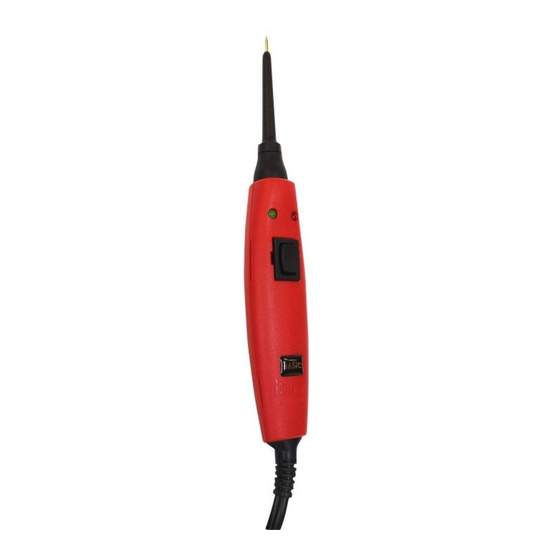
Power Probe Basic FEATURES Switch Latch (Included) Probe Tip Green Rocker Switch Battery Clips 6 -12 VOLTS Heavy-Duty 4mm Male/ Auxilliary Female Keyed Ground Connectors Lead 20 ft. Power Lead www.powerprobe.com • 800-655-3585... -
Page 6: Hook-Up
BATTERY QUICK SELF-TEST Rock the power switch forward (+), the LED indicator should light RED. Rock the power switch rearward (-), the LED indicator should light GREEN. The Power Probe is now ready to use. Forward Position Rearward Green Position www.powerprobe.com... -
Page 7: Polarity Testing
Power Probe Basic POLARITY TESTING By contacting the Power Probe tip to a POSITIVE (+), circuit will light the LED indicator RED. By contacting the Power Probe tip to a NEGATIVE (-), circuit will light the LED indicator GREEN. By contacting the Power Probe tip to an OPEN, circuit will be indi- cated by the LED indicator not lighting. -
Page 8: Continuity Testing
Power Probe Basic CONTINUITY TESTING By using the Probe Tip together with the auxiliary ground lead, conti- nuity can be tested on wires and components that are disconnect- ed from the vehicle’s electrical system. When continuity is present, the LED indicator will light GREEN. -
Page 9: Activating Removed Components
Power Probe Basic ACTIVATING REMOVED COMPONENTS By using the Power Probe tip together with the auxiliary ground lead, components can be activated, thereby testing their function. Connect the negative auxiliary clip to the negative terminal of the component being tested. -
Page 10: Testing Trailer Lights And Connections
Power Probe Basic TESTING TRAILER LIGHTS AND CONNECTIONS 1. Connect the Power Probe Basic to a good battery. 2. Clip the auxiliary ground clip to the trailer ground. 3. Probe the contacts at the jack and apply voltage to them. This lets you check the function and location of the trailer lights. -
Page 11: Power Testing A Ground
Power Probe Basic POWER TESTING A GROUND First be sure the ground feed you are testing is really a ground feed. Do NOT activate electronic control circuits or drivers with 12 volts unless they are designed for 12 volts. Power Testing a Ground Feed, that uses 20 to 18 gauge wires is easy. -
Page 12: Activating Electrical Components With Positive (+) Voltage
GREEN to RED you may proceed with further activation. If the green indicator went off at that instant or if the circuit breaker tripped, the Power Probe has been overloaded. This could happen for the following reasons: • The contact is a direct ground. -
Page 13: Ground Switching A Circuit Having An Electrical Load
If the GREEN LED did not light during the test, or if the circuit breaker tripped, the Power Probe BASIC has been overloaded. This could happen for the following reasons: • The tip is connected directly to a positive circuit. -
Page 14: Replacing Old Rocker Switch
Power Probe Basic REPLACING OLD ROCKER SWITCH Rocker Switch slots makes it easy to replace a worn out switch in the field without having to send it in for repair. Remove the old rocker switch with a small screw driver or any flat end pry tool. Insert... -
Page 15: Following And Locating Short Circuits
Remove the blown fuse from the fuse box. Use the Power Probe tip to energize each of both contacts in the fuse box. The side which trips the Power Probe circuit breaker is the shorted circuit. - Page 16 CAMBIO DE TIERRA DE UN CIRCUITO QUE CONTIENE CARGA ELÉCTRICA ........... 27 REMPLAZO DE ROCKER SWITCH ..........28 INSTALANDO EL SWITCH LATCH ..........28 SIGUIENDO Y LOCALISANDO LOS CORTO CIRCUITOS ..29 LA GARANTIA DE POWER PROBE ........... 29 www.powerprobe.com • 800-655-3585...
-
Page 17: Introducción
Power Probe Basic INTRODUCCIÓN Gracias por adquirir el Power Probe BASIC. Es el mejor valor para el ensayo de los problemas eléctricos del automóvil. Después de conectarlo a la batería del vehículo se puede ver si un circuito es positivo, negativo o abierto sondeándolo y observando el LED ROJO o VERDE. -
Page 18: La Seguridad
No se debe pasar tensión superior a la tensión nominal del Power Probe Basic. Revisa el Power Probe BASIC en busca de grietas o daños. Daños en caso de fugas de alto voltaje puede causar un riesgo de electro- cución. -
Page 19: Características
Power Probe Basic CARACTERÍSTICAS Switch Latch (Incluido) Punta de la Sonda Rojo Verde Rocker Switch Pinzas de la Batería 6 -12 VOLTS Tarea Pesada Cable de 4mm Masculino/ Hembra Conecto- TIerra res con Llave Auxiliar 20 pies Poder el Cable www.powerprobe.com... -
Page 20: Engánche
Precione el interruptor de alimentación hacia delante (+), el indica- dor LED se iluminará en ROJO. Precione el interruptor de encendido hacia atrás (-), el indicador LED se iluminará en VERDE. El Power Probe Basic está ahora listo para su uso. Posición Delantero Rojo Posición... -
Page 21: Prueba De Polaridad
Power Probe Basic PRUEBA DE POLARIDAD Contacta la punta del Power Probe al POSITIVO (-) del circuito se iluminará el indicador LED ROJO. Contacta la punta del Power Probe al NEGATIVO (-) del circuito se iluminará el indicador LED VERDE. -
Page 22: Pruebas De Continuidad
Power Probe Basic PRUEBAS DE CONTINUIDAD Mediante el uso de la punta junto con el cable de tierra auxiliar, se puede probar la continuidad en los cables y componentes que están desconectados del sistema eléctrico del vehículo. Cuando la continuidad está presente, el indicador LED se ilumina en verde. -
Page 23: Activación Componentes Removidos
Power Probe Basic ACTIVACIÓN DE COMPONENTES REMOVIDOS Mediante el uso de la punta del Power Probe junto con el cable de tierra auxiliar, los componentes pueden ser activados, probando así su función. Conecta la terminal positiva del componente, el indicador LED se iluminará... -
Page 24: Prueba De Luces Y Conexiones De Remolque
PRUEBA DE LUCES Y CONEXIONES DE REMOLQUE 1. Conecta el Power Probe Basic a una buena batería. 2. Engancha el clip de tierra auxiliar a la tierra del remolque. 3. Prueba los contactos del conector y aplique voltaje a ellos. -
Page 25: Prueba De Alimentación De Tierra
Power Probe Basic PRUEBA DE ALIMENTACIÓN DE TIERRA En primer lugar asegúrese de que la alimentación de tierra que se está probando es realmente un alimento de tierra. No se deben activar los circuitos de control electrónicos o controladores con 12 voltios al menos que estén diseñados para 12 voltios. -
Page 26: Activación De Los Componentes Eléctricos
Si el indicador verde se apaga en ese instante o si el interruptor au- tomático se dispara, el Power Probe se ha sobrecargado. Esto podría ocurrir por las siguientes razones: • El contacto es una tierra directa. -
Page 27: Cambio De Tierra De Un Circuito Que Contiene Carga Eléctrica
Si el LED verde no encendió durante la prueba, o si el interruptor au- tomático se dispara, El Power Probe Basic ha sido sobrecargado. Esto podría ocurrir por las siguientes razones: • La punta está conectada directamente a un circuito positivo. -
Page 28: Remplazo De Rocker Switch
Power Probe Basic REMPLAZO DEL ROCKER SWITCH Las ranuras del rocker switch hacen que sea más fácil re- emplazar el interruptor en ese instante, sin tener que enviarlo a reparación. Remueve el interruptor con un pequeño destornillador o herramienta de palanca plano extremo. Inserte la her- ramienta en el espacio y aplique cuidadosamente una ligera fuerza levantando y despegándolo de la unidad. -
Page 29: Siguiendo Y Localisando Los Cortocircuitos
Power Probe se dispara habrá verificado el cable con cortocircuito. Corta el cable y da energía a cada extremo con la punta de Power Probe. El lado que dispara el inter- ruptor es el área de donde está en corto. - Page 30 Power Probe Basic www.powerprobe.com 760 Challenger St. • Brea, CA 92821 800-655-3585 • Fax (714) 990-9478 www.powerprobe.com • 800-655-3585 300-00012...
Need help?
Do you have a question about the BASIC and is the answer not in the manual?
Questions and answers