
Related Manuals for Power Probe PPDCM80


Summary of Contents for Power Probe PPDCM80
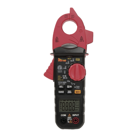
- Page 1 AMP CLAMP PPDCM80 User’s Manual • Amp Clamp - Page 2 • Pinza amperimétrica digital - Página 21 • Pince ampèremétrique numérique - Page 41 • Digitale strommesszange - Seite 59...
-
Page 2: Table Of Contents
PPDCM80 1. SAFETY INFORMATION .............. 3 1.1 Preparation ................3 1.2 During use ................3 1.3 Safety Symbols..............4 1.4 Maintenance ................ 5 2. DESCRIPTION ................5 2.1 Front Panel ................5 2.2 LCD Display................. 7 3. SPECIFICATIONS ................. 7 ............ -
Page 3: Safety Information
PPDCM80 1. Safety Information Warning Read and follow all safety guidelines outlined in this manual before use to prevent personal injury or damage to the meter. accordance with GB4793.1-1995 (EN61010-1,EN61010-2-032) safety requirements for electronic measuring instruments with and over-voltage category of CAT Ill 600V and pollution degree of 2. -
Page 4: Safety Symbols
PPDCM80 • Disconnect leads from circuit before switching func- tions/ranges. • Turn off power and discharge capacitors before mea- suring resistance, capacitance, diodes or continuity. • Do not connect the meter to a voltage source while in current, resistance, capacitance, diode or continuity modes. -
Page 5: Maintenance
PPDCM80 1.4 Maintenance • Maintenance/calibration should only be performed by professionals. • Before opening the case, always disconnect test leads from all energized circuits. • When the “ “ symbol appears, replace the batter- ies to avoid incorrect readings. • Clean meter with a damp cloth and mild detergent; do not use chemical solvents on the meter. - Page 6 PPDCM80 3080912 AMP CLAMP - 6 -...
-
Page 7: Lcd Display
PPDCM80 2.2 LCD Display Meter should be calibrated annually at 18°C- 28°C with a relative humidity of <80%. Auto-range Overload protection: CAT III 600V Max. voltage between ter- minals and 600V DC or AC earth ground: Operating altitude: Display: 3 3/4 digit LCD display Max. - Page 8 PPDCM80 AC Current Range Resolution Accuracy 1 mA 40 A 10 mA ±(2.5% of reading +5 digits) 80 A 100 mA • Max. input current: 80A AC • Frequency range: 40Hz~400Hz DC Current Range Resolution Accuracy 1 mA 40 A 10 mA ±...
- Page 9 PPDCM80 AC Voltage Range Resolution Accuracy 0,001 V 40 V 0,01 V ± (1,0 % of reading + 3 digits) 400 V 0,1 V 600 V • • Max. input voltage: 600V AC RMS • Frequency range: 40Hz~400Hz Note: At small voltage ranges, unsteady readings will appear be- fore the test leads make contact with the circuit.
- Page 10 PPDCM80 V Position Range Resolution Accuracy 99,99 Hz 0,001 Hz 999,9 Hz 0,01 Hz ± (1,5 % of reading + 5 digits) 9,999 kHz 0,1 Hz • Frequency range: 40Hz~10kHz • Input signal range:>0.2V AC RMS. As current increases, frequency increases as well.
- Page 11 PPDCM80 Resistance Range Resolution Accuracy ± (0.8 % of reading + 3 digits) ±(1.2% of reading +3 digits) • Open circuit voltage: 1V • Overload protection : 250V DC/AC RMS Continuity Range Resolution Accuracy If the measured resistance is less 9,999 Hz •...
-
Page 12: Operating Instructions
PPDCM80 Diode Range Resolution Accuracy Shows approx. forward voltage drop 0.001V of a diode. Temperature Range Resolution Accuracy -20°C~1000°C 1°C ± (0,8 % de lecture + 3 digits) -4°F~1832°F 1°F • Overload protection: 250V DC/AC RMS 4. Operating Instructions 4.1 Reading Hold •... -
Page 13: Manual Range
PPDCM80 4.4 Manual range The meter’s default range is “AUTO.” To select manual range, press to enter manual range. Each press of the button increases the range and returns to the lowest range when pressed at the highest range. Hold the button to return to autorange.Manual range cannot be used in current, frequency, duty cycle, diode, continuity, or temperature modes. -
Page 14: Preparing For Measurement
PPDCM80 4.8 Preparing for Measurement • Turn the rotary switch to turn on the meter. If the battery voltage is less than 3.6V, symbol will appear. Replace the batteries before use. • symbol means the input signal should not exceed the limit indicated to protect the meter from damage. -
Page 15: Ac Voltage
PPDCM80 4.10 AC Voltage Warning Electric shock hazard. Use caution to avoid damage or personal injury. Maximum input voltage: 600V AC RMS. • Turn the rotary switch to the voltage position. Press to switch to AC voltage. • Connect the red test lead to the INPUT jack and the black test lead to the COM jack. -
Page 16: Frequency/Duty Cycle
PPDCM80 4.12 Frequency/Duty Cycle Hz Position • Turn the rotary switch to the Hz position to measure frequency. • Press to switch to duty cycle. Press again to switch back to frequency. A Position (Clamp) Warning Electric shock hazard. Remove test leads before measuring current. -
Page 17: Resistance
PPDCM80 4.13 Resistance Warning Electric shock hazard. Turn off all power and discharge all capacitors before making resistance measurements. • Turn the rotary switch to the position. The default setting is resistance. • Connect the red test lead to the INPUT jack and the black test lead to the COM jack. -
Page 18: Capacitance
PPDCM80 4.15 Capacitance Warning Electric shock hazard. Turn off all power and discharge all capacitors before making resistance measurements. • Turn the rotary switch to the position.Press once to switch to capacitance mode. • Connect the red test lead to the INPUT jack and the black test lead to the COM jack. -
Page 19: Temperature
PPDCM80 4.17 Temperature • Turn the rotary switch to the °C/°F position. The default setting is °C. Press to switch to °F if necessary. • Connect the red(+) end of the K-Type thermocouple to the INPUT jack and the black(-) end to the COM jack. -
Page 20: Replacing Test Leads
PPDCM80 5.2 Replacing Test Leads Replace test leads if leads become damaged or worn. Warning Use meet EN 61010-031 standard, rated CAT III 600V, or better test leads. 6. Accessories • Test Leads - Spec : 1000 V, 10 A 1 pair •... - Page 21 PPDCM80 1. INFORMACIÓN DE SEGURIDAD ..........22 1.1 Preparación ................22 1.2 Durante el uso ..............22 1.3 Símbolos de seguridad ............23 1.4 Mantenimiento ..............24 2. DESCRIPCIÓN................24 2.1 Panel frontal ...............24 2.2 Pantalla LCD ..............26 3. ESPECIFICACIONES ..............26 ..........26 ...........27 4. INSTRUCCIONES DE USO ............31 4.1 Retención de medidas ............31...
-
Page 22: Información De Seguridad
PPDCM80 1. Información de seguridad Advertencia Lea y siga todas las pautas de seguridad descritas en este manual antes de usar el equipo, para evitar lesiones personales o daños en el medidor. GB / T 13978-92 de acuerdo con los requisitos de seguridad GB4793.1-1995 (EN61010-1, EN61010-2-032) para instrumentos de medición electrónicos con... -
Page 23: Símbolos De Seguridad
PPDCM80 • Desconecte las puntas de prueba del circuito antes de cambiar funciones / rangos. • Desconecte la alimentación y descargue los condensadores antes de medir resistencia, capacitancia, diodos o continuidad. • corriente, resistencia, capacitancia, diodo o continuidad. • No coloque el medidor en ningún entorno con alta presión, alta temperatura, polvo, gases explosivos o vapores. -
Page 24: Mantenimiento
PPDCM80 1.4 Mantenimiento • El mantenimiento / calibración solo debe ser realizado por profesionales. • Antes de abrir la caja, siempre desconecte las puntas de prueba de todos los circuitos energizados. • Cuando aparezca el símbolo “ “, reemplace las baterías para evitar lecturas incorrectas. - Page 25 PPDCM80 3080912 AMP CLAMP - 25 -...
-
Page 26: Pantalla Lcd
PPDCM80 2.2 Pantalla LCD El medidor debe calibrarse anualmente a 18 ° C- 28 ° C con una humedad relativa de <80%. Auto Rango: Proteción de sobrecargas: CAT III 600V Max. voltaje entre terminales y tierra: 600V DC o AC... - Page 27 PPDCM80 Corriente CA Rango Resolución Precisión 1 mA 40 A 10 mA ±(2.5% de lectura +5 dígitos) 80 A 100 mA • Max. Corriente de entrada: 80A AC • Rango de frecuencia: 40Hz ~ 400Hz Corriente CD Rango Resolución Precisión...
- Page 28 PPDCM80 Voltaje AC Rango Resolución Precisión 0,001 V 40 V 0,01 V ± (1,0 % de lectura + 3 dígitos) 400 V 0,1 V 600 V • • Máx. Voltaje de entrada: 600V CA RMS • Rango de frecuencia: 40Hz~400Hz Nota: En rangos de voltaje pequeños, aparecerán lecturas inestables antes de que las...
- Page 29 PPDCM80 Posición V Rango Resolución Precisión 99,99 Hz 0,001 Hz 999,9 Hz 0,01 Hz ± (1,5 % de lectura + 5 dígitos) 9,999 kHz 0,1 Hz • Rango de frecuencia: 40Hz~10kHz • Rango de señal de entrada:>0.2V CA RMS. A medida que aumenta la corriente, •...
- Page 30 PPDCM80 Resistencia Rango Resolución Precisión ± (0.8 % de lectura + 3 dígitos) ±(1.2% de lectura +3 dígitos) • Voltaje de circuito abierto: 1V • Protección de sobrecarga: 250V CD/CA RMS Continuidad Rango Resolución Precisión Si la resistencia medida es inferior 9,999 Hz •...
-
Page 31: Instrucciones De Uso
PPDCM80 Diodo Rango Resolución Precisión Muestra aprox. caída de tensión 0.001V directa de un diodo. Temperatura Rango Resolución Precisión -20°C~1000°C 1°C ± (0,8 % de lectura + 3 dígitos) -4°F~1832°F 1°F • Protección de sobrecarga: 250V CD/CA RMS 4. Instrucciones de uso 4.1 Retención de lecturas... -
Page 32: Rango Manual
PPDCM80 4.4 Rango manual El rango predeterminado del medidor es “AUTO”. Para seleccionar el rango manual, presione Cada vez que se presiona el botón, aumenta el rango y vuelve al rango más bajo cuando se presiona estando en el rango más alto. Mantenga presionado el botón para volver al rango automático. -
Page 33: Preparación De Medición
PPDCM80 4.8 Preparación de medición • Gire el selector para encender el medidor. Si el voltaje de la batería es inferior a 3,6 V, el símbolo aparecerá. Reemplace las baterías antes de usar. • El símbolo para proteger el medidor de daños. -
Page 34: Voltaje Ca
PPDCM80 4.10 Voltaje CA Advertencia Tenga precaución para evitar daños o lesiones personales. Voltaje de entrada máximo: 600V CA RMS. • Gire el selector a la posición de voltaje. Pulse para cambiar a voltaje CA . • Conecte la punta de prueba roja al conector INPUT y la punta de prueba negro al conector COM •... -
Page 35: Frecuencia/Ciclo De Trabajo
PPDCM80 4.12 Frecuencia / Ciclo de trabajo Posición Hz • Gire el selector a la posición Hz para medir la frecuencia. • Pulse para cambiar a ciclo de trabajo. Para volver a frecuencia. Posición A (Pinza) Advertencia Retire las puntas de prueba antes de realizar la medición. -
Page 36: Resistencia
PPDCM80 4.13 Resistencia Advertencia Apague la alimentación y descargue todos los condensadores antes de realizar las mediciones de resistencia. • Gire el selector a la posición • Conecte la punta de prueba roja al conector INPUT y la negra al conector COM. -
Page 37: Condensadores
PPDCM80 4.15 Condensador Advertencia Desconecte la alimentación y descargue todos los condensadores antes de realizar mediciones de resistencia. • Gire el selector a la posición . Presione una vez para cambiar al modo de capacitancia. • Conecte la punta de prueba roja al conector INPUT y la negra al conector COM. -
Page 38: Temperatura
PPDCM80 4.17 Temperatura • Gire el selector a la posición ° C / ° F. El ajuste predeterminado es ° C. Pulse para cambiar a ° F si es necesario. • Conecte el extremo rojo (+) del termopar tipo K a la toma INPUT y el extremo negro (-) a la toma COM. -
Page 39: Sustitución De Puntas De Prueba
PPDCM80 5.2 Sustitución puntas de prueba Reemplace las puntas de prueba si los cables se dañan o desgastan. Advertencia 6. Accesorios • Puntas de prueba - Espec : 1000 V, 10 A 1 par • Manual de usuario 1 unidad •... - Page 40 PPDCM80 ............41 .................41 1.2 Lors de l'utilisation ..............41 ..........42 1.4 Maintenance ...............43 2. DESCRIPTION ................43 2.1 Face avant ................43 ..............45 ................45 ..........45 ..........46 4. MODE D'EMPLOI ................50 4.1 Lecture Hold ...............50 4.2 Mode relatif .................50 ....50 4.4 Gamme manuelle ...............51 4.5 Commutateur de fonctions ..........51...
-
Page 41: Lors De L'utilisation
PPDCM80 Consignes de sécurité Avertissement d’endommager l’appareil. l’appareil. de l’appareil. 1.1 Préparation • Lors de l’utilisation de l’appareil, les utilisateurs doivent respecter les normes Ne pas faire mauvais usage de l’instrument • • avant de les utiliser. • Utiliser seulement les cordons de test fournis avec l’appareil. Remplacer 1.2 Lors de l’utilisation... - Page 42 PPDCM80 • • • • Ne pas placer l’appareil dans un endroit sous haute pression, sous haute • S’assurer que l’appareil fonctionne correctement en testant d’abord une source • 1.3 Pictogrammes de sécurité au mode d’emploi. DANGEREUX NON ISOLANTS est admis...
-
Page 43: Maintenance
PPDCM80 1.4 Maintenance • professionnels. • circuits sous tension. • Quand le symbole “ incorrectes • de solvants chimiques sur l’appareil. • Tourner le commutateur rotatif sur la position OFF lorsque l’appareil n’est pas • 2. Description de l’instrument •... - Page 44 PPDCM80 3080912 AMP CLAMP - 44 -...
- Page 45 PPDCM80 3.1 Caractéristiques générales Gamme automatique : Protection contre les surcharges : CAT III 600 V Tension max. entre les bornes et la 600 V DC ou AC terre : Fonctionnement en altitude : Lecture max. : 4000 limite de la gamme :...
- Page 46 PPDCM80 3.2 Caractéristiques techniques Courant AC Gamme Résolution Précision 1 mA 40 A 10 mA ± (2,5 % de lecture + 5 digits) 80 A 100 mA • • Courant DC Gamme Résolution Précision 1 mA 40 A 10 mA ±...
- Page 47 PPDCM80 Tension AC Gamme Résolution Précision 0,001 V 40 V 0,01 V ± (1,0 % de lecture + 3 digits) 400 V 0,1 V 600 V • • • Remarque : Dans les petites gammes de tension, des lectures instables apparaîtront avant que les cordons de test n’entrent en contact avec le circuit.
- Page 48 PPDCM80 Position V Gamme Résolution Précision 99,99 Hz 0,001 Hz 999,9 Hz 0,01 Hz ± (1,5 % de lecture + 5 digits) 9,999 kHz 0,1 Hz • • • • • Rapport cyclique Gamme Résolution Précision 0,5 - 99,5 % 0,1 % ±...
- Page 49 PPDCM80 Résistance Gamme Résolution Précision ± (0,8 % de lecture + 3 digits) ± (1,2 % de lecture + 3 digits) • Tension en circuit ouvert : 1 V • Protection contre les surcharges : 250 V DC/AC Continuité Gamme Résolution...
-
Page 50: Mode D'emploi
PPDCM80 Diode Gamme Résolution Précision 0.001V tension directe d’une diode. Température Gamme Résolution Précision -20°C~1000°C 1°C ± (0,8 % de lecture + 3 digits) -4°F~1832°F 1°F • Protection contre les surcharges : 250 V DC/AC RMS 4. Mode d’emploi 4.1 Lecture HOLD •... -
Page 51: Gamme Manuelle
PPDCM80 4.4 Gamme manuelle manuelle, appuyer sur pour entrer dans le mode gamme manuelle. basique lorsqu’on appuie sur la plus grande gamme. Maintenir le bouton pour 4.5 Basculeur de fonctions • En position courant et tension, appuyer sur pour basculer entre les modes AC et DC. -
Page 52: Courant Ac/Dc
PPDCM80 4.8 Préparation de la mesure • Tourner le commutateur rotatif pour allumer l’appareil. Si la tension de la batterie apparaîtra. Remplacer les piles avant utilisation. • Le symbole • Placer le commutateur rotatif sur la position et la gamme de mesure correcte. -
Page 53: Tension Ac
PPDCM80 4.10 Tension AC Avertissement • Tourner le commutateur rotatif sur la position tension. • Appuyer sur pour passer au courant alternatif. • la prise COM. • • Remarque : une alarme. 4.11 Tension continue Avertissement • Tourner le commutateur rotatif sur la position tension. - Page 54 PPDCM80 4.12 Fréquence/rapport cyclique Position Hz • • Appuyer sur pour basculer au rapport cyclique. Appuyer une nouvelle Position A (pince) Avertissement Retirer les cordons de test avant de mesurer le courant. • Tourner le commutateur rotatif sur l’une des positions actuelles.
-
Page 55: Diode
PPDCM80 l’exactitude de ces mesures. 4.13 Résistance Avertissement • Tourner le commutateur rotatif sur la position • • • Remarque : secondes pour que les lectures se stabilisent, ce qui est normal pour les mesures 4.14 Diode • Tourner le commutateur rotatif sur la position . - Page 56 PPDCM80 4.15 Capacité Avertissement • Tourner le commutateur rotatif sur la position . Appuyer une fois pour • prise COM. • • Remarque : (>4 mF). 4.16 Continuité Avertissement • Tourner le commutateur rotatif sur la position . Appuyer 2 fois pour passer en mode diode.
-
Page 57: Maintenance
PPDCM80 4.17 Température • Appuyez sur • • • 4.18 Détecteur de tension sans contact (NCV) Remarque : 5. Maintenance 5.1 Remplacement des piles Avertissement Avertissement alcalines, standard (carbone-zinc) ou rechargeables Piles (Ni-CAd, Ni-MH, etc). • Si le signe •... -
Page 58: Remplacement Des Cordons De Test
PPDCM80 5.2 Remplacement des cordons de test Avertissement ou de meilleurs cordons de test. 6. Accessoires • Cordons de test - Spec : 1000 V, 10 A 1 paire • • • - 58 -... - Page 59 PPDCM80 1. SICHERHEITSINFORMATIONEN ..........60 1.1 Vorbereitung ...............60 1.2 Während des Betriebs ............60 1.3 Sicherheitssymbole ............61 1.4 Wartung ................62 2. BESCHREIBUNG ................62 2.1 Frontplatte ................62 2.2 LCD-Anzeige ..............64 3. SPEZIFIKATIONEN ..............64 ..........64 ..........65 4. BEDIENUNGSANLEITUNG ............69 4.1 Halten des Ablesewerts ............69 4.2 Relativmodus ..............69...
-
Page 60: Sicherheitsinformationen
PPDCM80 1. Sicherheitsinformationen Warnhinweis Lesen und befolgen Sie vor der Verwendung alle in diesem Handbuch aufgeführten Sicherheitsrichtlinien, um Verletzungen oder Beschädigungen am Messgerät zu vermeiden. Dieses Messgerät erfüllt die allgemeinen Anforderungen für Digital-Multimeter GB/T 13978-92 Übereinstimmung Sicherheitsanforderungen GB4793.1-1995 (EN61010-1,EN61010-2-032) für elektronische Messgeräte mit Überspannungskategorie CAT Ill 600V und Verschmutzungsgrad 2. -
Page 61: Sicherheitssymbole
PPDCM80 • Gehen Sie bei der Arbeit mit Effektivspannungen über 60 V DC oder 30 V AC immer mit großer Sorgfalt vor. Halten Sie die Finger hinter den Sondenbarrieren, wenn Sie Spannungsmessungen durchführen. • Wählen Sie den größten Bereich, wenn der zu messende Werte vorher unbekannt ist. -
Page 62: Wartung
PPDCM80 1.4 Wartung • Wartungs- Kalibrierarbeiten sind ausschließlich durch Fachleute vorzunehmen. • Trennen Sie vor dem Öffnen des Gehäuses immer die Messleitungen von allen stromführenden Schaltkreisen. • Wenn das Symbol “ “, rerscheint, tauschen Sie die Batterien aus, um falsche Messwerte zu vermeiden. - Page 63 PPDCM80 3080912 AMP CLAMP - 63 -...
-
Page 64: Lcd-Anzeige
PPDCM80 2.2 LCD-Anzeige Das Messgerät ist einmal jährlich bei einer Temperatur von 18 °C - 28 °C und einer relativen Luftfeuchtigkeit von <80 % zu kalibrieren. Automatische Bereichswahl: Überlastschutz: CAT III 600V Max. Spannung zwischen Klemmen 600 V DC oder AC und Erde: Einsatzhöhe:... - Page 65 PPDCM80 Wechselstrom Bereich Genauigkeit 1 mA 40 A 10 mA (2,5 % des Anzeigewerts +5 Stellen) 80 A 100 mA • Max. Eingangsstrom: 80 A AC • Frequenzbereich: 40 Hz ~ 400 Hz Gleichstrom Bereich Genauigkeit 1 mA 40 A...
- Page 66 PPDCM80 Wechselstrom Spannung Bereich Genauigkeit 0,001 V 40 V 0,01 V (1,0 % des Anzeigewerts +3 Stellen) 400 V 0,1 V 600 V • Eingangsimpedanz: 10 MQ • Max. Eingangsspannung: 600 V AC eff. • Frequenzbereich: 40 Hz~400 Hz Hinweis:: Bei kleinen Spannungsbereichen werden uneinheitliche Messwerte angezeigt, bevor die Messleitungen in Kontakt mit dem Stromkreis kommen.
- Page 67 PPDCM80 V-Stellung Bereich Genauigkeit 99,99 Hz 0,001 Hz 999,9 Hz 0,01 Hz (1,5 % des Anzeigewerts +5 Stellen) 9,999 kHz 0,1 Hz • Frequenzbereich: 40Hz~10kHz • Eingangssignalbereich: >0,2 V AC eff. Mit steigender Stromstärke steigt auch die Frequenz. • Eingangsimpedanz: 10 MQ •...
- Page 68 PPDCM80 Widerstand Bereich Genauigkeit (0,8 % des Anzeigewerts +3 Stellen) (1,2 % des Anzeigewerts +3 Stellen) • Offene Klemmenspannung: 1 V • Überlastschutz: 250 V DC/AC eff Durchgang Bereich Genauigkeit Beträgt der gemessene Widerstand 9,999 Hz • Überlastschutz: 250 V DC/AC eff Kapazität...
-
Page 69: Bedienungsanleitung
PPDCM80 Diode Bereich Genauigkeit Zeig die ungefähre Vorwärtsspannung 0.001V einer Diode an. Temperatur Bereich Genauigkeit -20°C~1000°C 1°C ±(0,8 % des Anzeigewerts +3 Stellen) -4°F~1832°F 1°F • Überlastschutz: 250V DC/AC eff. 4. Bedienungsanleitung 4.1 Halten des Ablesewerts • Um einen Ablesewert auf der Anzeige zu halten, drücken , woraufhin der aktuelle Wert am Display verbleibt. -
Page 70: Manueller Bereich
PPDCM80 4.4 Manueller Bereich Der voreingestellte Bereich des Messgeräts ist „AUTO“. Um den manuellen Bereich aufzurufen, drücken Sie Mit jedem Druck der Taste wird der Bereich erhöht. Wenn nach Erreichen des höchsten Bereichs die Taste gedrückt wird, kehrt das Gerät zum niedrigsten Bereich zurück. -
Page 71: Vorbereitung Der Messung
PPDCM80 4.8 Vorbereitung der Messung • Schalten Sie das Messgerät mit dem Drehschalter ein. Bei einer Batteriespannung von weniger als 3,6 V erscheint das Symbol . Tauschen Sie dann vor Verwendung die Batterien aus. • Das Symbol weist darauf hin, dass das Eingangssignal den angegebenen Grenzwert nicht überschreiten darf, um das Messgerät vor Beschädigungen zu... -
Page 72: Wechselspannung
PPDCM80 4.10 Wechselspannung Warnhinweis Stromschlaggefahr. Mit Sorgfalt vorgehen, um Sachschäden oder Verletzungen zu vermeiden. Maximale Eingangsspannung: 600 V AC eff. • Stellen Sie den Drehschalter auf die Spannungsposition. • Drücken Sie , um auf Wechselspannung umzuschalten. • Verbinden Sie die rote Messleitung mit der Buchse INPUT und die schwarze mit der Buchse COM. -
Page 73: Frequenz/Tastverhältnis
PPDCM80 4.12 Frequenz/Tastverhältnis Hz-Stellung • Stellen Sie den Drehschalter auf die Hz-Position, um die Frequenz zu messen. • Drücken Sie , um auf Tastverhältnis umzuschalten. Drücken Sie die Taste erneut, um zum Frequenzmodus zurückzukehren. A-Stellung (Zange) Warnhinweis Stromschlaggefahr. Messleitungen vor der Strommessung entfernen. -
Page 74: Widerstand
PPDCM80 Hinweis: 1. Der Frequenzbereich beträgt 10 Hz~10 kHz. Frequenzmessungen außerhalb dieses Bereichs sind möglich, aber deren Genauigkeit kann nicht garantiert werden. 2. „ “ weist darauf hin, dass die maximale Eingangsspannung 600 V AC (nicht eff.) beträgt. 4.13 Widerstand Warnhinweis Stromschlaggefahr. -
Page 75: Kapazität
PPDCM80 4.15 Kapazität Warnhinweis Stromschlaggefahr. Vor Durchführung von Widerstandsmessungen den Strom abschalten und alle Kondensatoren entladen. • Stellen Sie den Drehschalter auf die Position . Drücken Sie einmal , um auf den Kapazitätsmodus umzuschalten. • Schließen Sie die rote Messleitung an die Buchse INPUT und die schwarze an die Buchse COM an. -
Page 76: Temperatur
PPDCM80 4.17 Temperatur • Stellen Sie den Drehwahlschalter auf „°C/°F“. Die Voreinstellung lautet °C. Drücken Sie bei Bedarf , um auf °F umzuschalten. • Verbinden Sie das rote (+) Ende des Typ-K-Thermoelements mit der Buchse INPUT und das schwarze (-) Ende mit der Buchse COM. -
Page 77: Austausch Der Messleitungen
PPDCM80 5.2 Austausch der Messleitungen Tauschen Sie Messleitungen aus, die beschädigt oder verschlissen sind. Warnhinweis Messleitungen gemäß Norm EN 61010-031und mit Schutzklasse CAT III 600 V • Messleitungen - Spez.: 1000 V, 10 A 1 paar • Benutzerhandbuch 1 St. - Page 78 PPDCM80 - 78 -...
- Page 79 PPDCM80 - 79 -...
- Page 80 MGL International EU: MGL EUMAN S.L. Parque empresarial de Argame C/ Picu Castiellu, Parcelas I-1 a I-4 E-33163, Morcín Asturias (Spain) USA: POWER PROBE TEK LLC 760 Challenger St Brea, CA 92821 2810 Coliseum Centre Dr #100 Charlotte, NC 28217...
Need help?
Do you have a question about the PPDCM80 and is the answer not in the manual?
Questions and answers