
Subscribe to Our Youtube Channel
Related Manuals for Power Probe IV


Summary of Contents for Power Probe IV
- Page 1 Power Probe IV Users Manual The Next Generation of Diagnostics www.powerprobe.com · 800-655-3585...
-
Page 3: Table Of Contents
Power Probe IV Page 1 Table of Contents Introduction .................. 2 Safety ................... 3 Appearance and Controls ............4-5 Start Up ..................6 Mode Navigation ................ 7 Testing and Measuring Operations • DC Voltage in VDC Mode ............. • Activating Components .............. -
Page 4: Introduction
(1) Since the Power Probe IV is connected to the battery, you can apply battery power or battery ground directly to the tip of the tool. You can energize and activate components to verify their correct operation. -
Page 5: Safety
• When testing voltage exceeding 30V AC RMS, 42V AC Peak, or 60V DC, be particularly careful to avoid any electric shock. • Check the Probe IV case for cracks or damage. Damage to the case can leak high voltage causing a potential electrocution risk. -
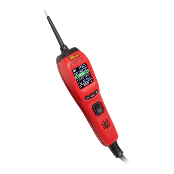
Page 6: Appearance And Controls
Power Probe IV Page 4 Appearance and Controls Removable Probe Tip -Uses standard 4mm banana type connector enabling use of different probes, leads, or extensions. LED, Green (-) -Will light indicating a path to ground. More than10Ω resistance and/or more than 0.5 volts on a ground circuit, the Green LED will not illuminate. - Page 7 Power Probe IV Page 5 Appearance and Controls Rear Cover IP4363215 Serial Number Circuit Breaker (replaceable) Part #30-00041 USB Connecter 5 x 20mm 20A Fast Blow Fuse; Part #30-00040 www.powerprobe.com · 800-655-3585...
-
Page 8: Start Up
Alligator Clip LED Flashlight Adapter Flashlight is a standard feature on the Power Probe IV. The two bright 23 ft. Power white LEDs are always ON mak- Lead ing it possible to see under dash- boards and in dark areas. -
Page 9: Mode Navigation
7. DRV TST – Supplies safe voltage for testing computer driver circuits. 8. PPECT – Detects the open circuit signal from Power Probe ECT2000 to assist in locating opens. Refer to sections: Testing and Measuring Operations and Advanced Testing Operations for further mode descriptions and suggested applications. -
Page 10: Testing And Measuring Operations
LED will illuminate and the speaker will make a low-tone. This greatly simplifies testing as the Power Probe IV’s Red/Green LEDs and speaker tones provide a quick indication if there are excessive voltage drops or circuit resistance. If the LEDs do not illumi- nate and there is no tone from the speaker, you know instantly there may be a circuit problem. -
Page 11: Activating Components
Activating Electrical Components in VDC Mode is one of the main features that make the Power Probe IV very useful when testing. Being able to ap- ply battery power or ground right to the probe tip gives you the ability to activate and dynamically test electrical components such as lights, motors, and solenoids. - Page 12 PFT can also be used like a standard ohmmeter. PFT displays both Battery and Tip voltage simultaneously for easy voltage drop testing. In this mode, the Power Probe IV display will show: - Total circuit Resistance on the center screen. - Probe Tip Voltage.
- Page 13 Power Probe IV Page 1 1 Testing and Measuring Operations Power Feed Testing To test, first disconnect the device or load being operated from the circuit, then contact the probe tip to the circuit being tested. Removing the component from the circuit prevents the component load from affecting and altering the resistance reading.
-
Page 14: Ac Voltage Measurement (Rms)
The Power Probe IV can safely measure up to 70 VAC. WARNING Do not use the Power Probe IV to test AC line voltage, such as a 120V wall plug. Attempting to use the Power Probe IV on AC line voltage will damage the probe and could cause personal injury. -
Page 15: Ac Voltage Measurement (P To P)
For example, if you have an AC signal that alternates from -50V to +50V the Power Probe IV will display a P-P voltage of 100V, a Min voltage of -50V and a Max voltage of +50V. -
Page 16: Frequency Measurement
– Pulse Width and + Pulse Width in milliseconds on the bottom line. The Power Probe IV can measure frequencies from 1Hz to 9999Hz. FRQ CTR can be used for tests where frequency or pulse width are needed such as MAF sensors, wheel sensors, etc. -
Page 17: Advanced Testing Operations
ECT Receiv- er alone. When you select the ECT Mode, the Power Probe IV is now specifically tuned to detect the ECT open circuit signal. The Power Probe IV is meant to work by direct contact to the circuit. -
Page 18: Fuel Injector Mode
FUEL INJ = Fuel Injector Mode is specifically set-up for fast and easy injector circuit diagnosis. One quick connection to the circuit and the Power Probe IV will display all the needed fuel injector testing information that would normally require using an lab-scope. - Page 19 Power Probe IV Page 17 Advanced Testing Operations Fuel Injector Mode • Select FUEL INJ from the Power Probe IV’s test menu. • Back-probe on the negative side of the injector, either at the injector or at the PCM. • These four data points represent the corresponding waveform points.
- Page 20 When the Power Probe IV is in Driver Test Mode, it will provide the necessary voltage and pull-up resistance to ensure proper driver testing.
-
Page 21: Driver Test Mode
Power Probe IV Page 19 Advanced Testing Operations Driver Testing Driver Testing Explained: Suppose you had a shorted solenoid that was not working. You know the solenoid will have to be replaced, but you don’t yet know if the driver circuit was damaged and you may need to also re- place the module. -
Page 22: Tool Repair Operations
Tool Repair Operations Rocker Switch Replacement The Power Probe IV Rocker Switch is used constantly and arcing can occur across the switch con- tacts and eventually the switch can wear out. The Power Probe IV also has an Automatic Resetting 8Amp Thermal Circuit Breaker and like the Rocker Switch, the Circuit Breaker can also wear out over time.If this occurs, the Rocker Switch and... - Page 23 Power Probe IV Page 21 Tool Repair Operations Circuit Breaker Replacement Follow the instructions below to replace a worn Circuit Breaker - Unscrew the two retaining screws and remove the rear cover. Using an appropriate pry tool or small screwdriver, carefully pry the Circuit Breaker towards the tip to dis-engage it from the breaker terminals.
-
Page 24: Specifications
Power Probe IV Page 22 Specs Product Specifications Min Operating Voltage …………………………..8 VDC Max Operating Voltage …………………………..30 VDC Max Tip Voltage ……………………………………..450 Volts Probe Tip Resistance to Ground ………………..130K Ohms Computer Safe ……………………………………..0.1mA floating tip Voltage Measurement …………………………….. -
Page 25: Notes
Power Probe IV Page 23 Notes www.powerprobe.com · 800-655-3585... - Page 26 Power Probe IV Page 24 Notes www.powerprobe.com · 800-655-3585...
-
Page 27: Warranty
From the date of purchase, we will war- ranty/repai Power Probe products for one (1) year against defects in parts and work- manship. All repair due to misuse will be charged a fee not to exceed the cost of the tool. - Page 28 Power Probe, Inc. 760 Challenger St. Brea, California 92821 toll free 800.655.3585 local 714.990.9443 fax 714.990.9478 DOC# 300-00010 REV 00 The Next Generation of Diagnostics www.powerprobe.com · 800-655-3585...
Need help?
Do you have a question about the IV and is the answer not in the manual?
Questions and answers