Table of Contents
Advertisement
Available languages
Available languages
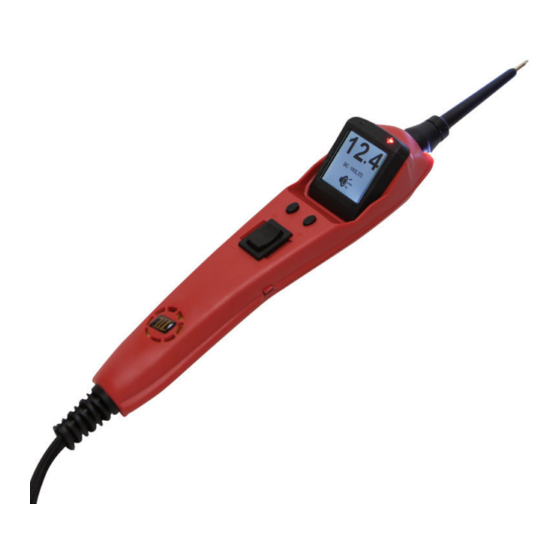
Power Probe 3EZ
5000815
INTRODUCTION
Thank you for purchasing the Power Probe 3EZ (PP3EZ). The
PP3EZ includes all the powerful testing modes and features
of the Power Probe 3S plus now includes 2 new modes - EZ
Learning Mode and EZ Diagnostics Mode. The PP3EZ speeds
you through the diagnosing of 12 to 24 volt automotive elec-
trical systems. After connecting the PP3EZ's clips to the ve-
hicle's battery, the automotive technician can determine at a
glance, the voltage level and the polarity of a circuit without
running for a voltmeter or reconnecting hook-up clips from
one battery pole to the other. The power switch allows the
automotive technician to conduct a positive or negative bat-
tery current to the tip for activating and testing the function of
electrical components without wasting time with jumper leads.
WWW.POWERPROBETEK.COM
Advertisement
Chapters
Table of Contents

Related Manuals for Power Probe 3EZ


Summary of Contents for Power Probe 3EZ
- Page 1 Thank you for purchasing the Power Probe 3EZ (PP3EZ). The PP3EZ includes all the powerful testing modes and features of the Power Probe 3S plus now includes 2 new modes - EZ Learning Mode and EZ Diagnostics Mode. The PP3EZ speeds you through the diagnosing of 12 to 24 volt automotive elec- trical systems.
- Page 2 III & CAT IV. An absolute must for every automotive technician looking for a fast and accurate solution to electrical systems diagnostics. Before using the Power Probe 3EZ please read the instruction booklet carefully. If the equipment is used in a manner not specified by the manufacturer, the protection provided by the equipment may be impaired.
- Page 3 If the test leads need to be replaced, you must use a new one which should meet EN 61010-031 standard. The Power Probe 3EZ is NOT to be used with 110/220V HOME electrical, it is only for use with 12-24V systems.
-
Page 4: Table Of Contents
Back Cover IMPORTANT TIP: When powering-up components, you can in- crease the life of your Power Probe switch if you first press the switch, then contact the tip to the component. The arcing will take place at the tip instead of the contacts of the switch. -
Page 5: Hook-Up And Quick Self-Test
HOOK UP AND QUICK SELF-TEST Unroll the Power Probe cable. Connect the RED battery hook- up clip to the POSITIVE terminal of the vehicle’s battery. Con- nect the BLACK battery hook-up clip to the NEGATIVE termi- nal of the vehicle’s battery. When the PP3EZ is first connected... -
Page 6: Circuit Breaker
TURNING AUDIO TONE ON & OFF CIRCUIT BREAKER In Voltmeter Mode (Mode #1) with the circuit breaker tripped, the display will show “Circuit Breaker Tripped”(see page 11-12 for detail) All other functions of the PP3EZ are still active. This means that you can still probe a circuit and observe the volt- age reading. -
Page 7: Introduction To "Ez
INTRODUCTION TO “EZ” The Power Probe 3EZ is the latest addition to the Power Probe line of circuit testers. It includes all the powerful testing modes and features of the Power Probe 3S and now includes 2 new modes- EZ Learning Mode and EZ Diagnostics Mode. - Page 8 Each test section includes a readable QR code that will ac- cess online video content explaining the test procedure. 5V REF mode is used together with the Power Probe Tek 5V Adapter Tip (# PPT5VA). With the Adapter Tip installed on the probe and applying power, the probe will no longer output full battery voltage.
-
Page 9: Testing Section
TESTING SECTION Continuity testing Activating components out of vehicle’s electrical system Testing trailer lights and connections. Activating electrical components in the Vehicle Activating electrical components with Ground Checking for bad ground contacts Following & Locating Short Circuits WWW.POWERPROBETEK.COM... -
Page 10: Continuity Testing
The PP3EZ indicates continuity using 2 resistance levels. When the Power Probe tip has a resistance to ground less than 20K Ohms but greater than approx. 650 Ohms the LCD will indicate “00.0” volts but no Green “-” LED. But when the resistance to ground less than approx. -
Page 11: Activating Components In Hand
If the green negative sign “-“ LED went off at that instant or if the circuit breaker tripped, the Power Probe has been overloaded. This could happen for the following reasons: • The contact you are probing is a direct ground or negative voltage. - Page 12 ACTIVATING COMPONENTS IN HAND WWW.POWERPROBETEK.COM...
- Page 13 TRAILER LIGHT CONNECTIONS 1. Connect the PP3EZ to a good battery. 2.Clip the auxiliary ground clip to the trailer ground. 3. Probe the contacts at the jack and then apply voltage to them. This lets you check the function and orientation of the connector and trailer lights.
- Page 14 If the green indica- tor went off at that instant or if the circuit breaker tripped, the Power Probe has been overloaded. This could happen for the following reasons: •The contact is a direct ground.
- Page 15 ACTIVATING COMPONENTS ON VEHICLE WWW.POWERPROBETEK.COM...
-
Page 16: Activating Electrical Components With Ground
(-) came on you may proceed with further ac- tivation. If the green indicator went off at that instant or if the circuit breaker tripped, the Power Probe has been overload- ed. This could have happened for the following reasons: •... - Page 17 ACTIVATING COMPONENTS WITH GROUND WWW.POWERPROBETEK.COM...
- Page 18 Locate the color-coded wire in the harness and expose it. Probe through the insulation with the Power Probe tip and depress the power switch forward to ac- tivate and energize the wire. If the Power Probe circuit break- er tripped you have verified the shorted wire.
-
Page 19: Following & Locating Short Circuits
FOLLOWING AND LOCATING SHORT CIRCUITS The wire end which trips the Power Probe circuit breaker again is the shorted circuit and will lead you to the shorted area. Follow the wire in the shorted direction and repeat this process until the short is located. The Power Probe ECT3000 uses a wireless non-contact technique that guides you to the short/open location. -
Page 20: Modes
MODES The Power Probe 3EZ has been designed to work the same as the previous Power Probe circuit testers. Using the ad- vanced features and modes is optional. However, understand- ing them will expand your diagnosing capabilities. The LCD display indicates voltage levels of the circuit along with an identifying symbol showing you what mode it is in. - Page 21 MODES on the display, the sound of the signals will be monitored and heard through the PP3EZ speaker. The peak to peak threshold levels are pre-selected by the operator in “Mode 5”. See Mode #5 for more information on setting threshold levels. Placing the PP3EZ probe tip next to a sparkplug wire (NOT probing it directly), allows you to monitor the sound of the ignition pulses at the same time display a peak to peak reading The PP3EZ...
- Page 22 MODES Mode #3 Max Peak Mode: The Max Peak Mode monitors the probed circuit and captures the highest detected voltage. Place the PP3EZ into Max Peak Mode by selecting MAX PEAK from the menu. Probe the circuit and the PP3EZ instantly dis- plays and holds the highest voltage reading.
- Page 23 MODES pressing the left button as often as necessary. An APPLICATION for the use of the Min Peak Mode: Lets say you have a circuit that is suspect of losing a connection and the voltage drops, causing something to turn off or malfunc- tion.
- Page 24 MODES WWW.POWERPROBETEK.COM...
-
Page 25: Specifications
SPECIFICATIONS Storage temperature/humidity: -20 to 70 C, 70% RH max Operating temperature/humidity: -10 to 50 C, 70% RH max Pollution degree: 2 DC Voltage 0 to +70 Volts +1 digit P-P Voltage ....0 to +70 Volts Frequency Response ..10Hz to 10kHz (for tone pass through) P-P display ... - Page 26 SPECIFICATIONS WWW.POWERPROBETEK.COM...
-
Page 27: Replacement Parts
REPLACEMENT PARTS The Power Probe 3EZ is engineered for years of reliable service. Some components can wear out over time with heavy use. Replacement parts can be obtained from your tool dealer or by contacting Power Probe Tek’s Technical Support depart- ment at 1-800-655-3585 or email to support@pp-tek.com... - Page 28 NOTES: 760 Challenger Street Brea, California 92821 Phone: 800-655-3585 Local: 714-990-9443 fax: 714-990-9478 support@pp-tek.com WWW.POWERPROBETEK.COM...
- Page 29 Power Probe 3EZ 5000815 INTRODUCCION Gracias por comprar el Power Probe 3EZ (PP3EZ). El PP3EZ incluye todas las funciones poderosas de prueba y Caracteis- ticas del Power probe 3S y ahora incluye 2 funciones nuevas: function de aprendizaje EZ y function de diagnostico EZ. El PP3EZ te ayuda repidamente a diagnosticar los sistemas eléctricos automotrices de 12 a 24 voltios.
- Page 30 Antes de usar el Power Probe 3EZ, lea atentamente el manual de instrucciones. Si el equipo se utiliza de una manera no especificada por el fabricante, la protección proporcionada para el equipo puede...
- Page 31 Si los cables de prueba necesitan ser reemplazados, debe usar uno nuevo que cumpla con la norma EN 61010-031. El Power Probe 3EZ NO debe usarse con 110 / 220V de tu casa, solo para uso con sistemas de 12-24v.
- Page 32 Garantia de el Power Probe CONSEJO IMPORTANTE: Al encender los componentes, puede aumentar la vida útil de su interruptor Power Probe si primero presiona el interruptor y luego contacta la punta con el componente. El arco se realizará en la punta en lugar de los contactos del interruptor.
-
Page 33: Conexion Y Auto Prueba Rapida
CONEXIÓN Y AUTO PRUEBA RÁPIDA Desenrolle el cable de la sonda de alimentación. Conecte el clip de conexión de la batería ROJA al terminal POSITIVO de la batería del vehículo. Conecte el clip de conexión de la batería NEGRA al terminal NEGATIVO de la batería del vehícu- lo. -
Page 34: Activacion Y Desactivasion Del Tono Auditivo
ACTIVACION Y DESACTIVASION DEL TONO AUDITIVO PROTECTOR DE CIRCUITO En la funcion Voltímetro (funcion #1) con el protector de cir- cuito activado, la pantalla mostrará “CIRCUITO PROTECTOR ACTIVADO” (vea la página 11-12 para más detalles) Todas las otras funciones del PP3EZ están activas. Esto significa que aún puede probar un circuito y observar la lectura de volta- je. -
Page 35: Introduccion De "Ez
INTRODUCCION A “EZ” El Power Probe 3EZ es la última adición a la línea de probadores de circuitos Power Probe. Incluye todos Las funciones potentes de prueba del Power Probe 3S y ahora incluye 2 funciones nue- vas: funcion de APRENDIZAJE EZ y funcion de DIAGNOSTICO EZ. -
Page 36: Guia De Diagnosticos
La funcion de referencia de 5 voltios se usa junto con la punta del adaptador ESPECIAL Power Probe Tek 5V. (N / P PPT5VA) Con la punta del adaptador instalada en la herramienta y apli- cando energia positiva, la punta ya no superará el voltaje total de la batería. -
Page 37: Seccion De Diagnostico
FUNCIONES DE PRUEBAS Prueba de continuidad Activación de componentes fuera del sistema eléctrico del vehículo Prueba de luces y conexiones del remolque Activación de componentes eléctricos en el vehículo Activación de componentes eléctricos con Ground Comprobando contactos de tierra malos Siguiendo y Localizando Corto circuitos WWW.POWERPROBETEK.COM... -
Page 38: Probando Continuidad
PRUEBA DE CONTINUIDAD Mientras que el PP3EZ está en la funcion Voltímetro y utilizan- do la punta de Power Probe en conexión con la tierra del cha- sis o el cable de tierra auxiliar, se puede probar la continuidad de los cables y componentes conectados o desconectados del sistema eléctrico del vehículo. -
Page 39: Activando Componentes Eléctricos Fuera De El Vehiculo
ACTIVANDO COMPONENTES A MANO Mientras que el PP3EZ se encuentra en la funcion Voltímetro y utilizando la punta de la herramienta de alimentación en conexión con el cable de tierra auxiliar, los componentes se pueden activar directamente en su mano, probando así su funcion Conecte la pinza de el cable auxiliar negativo al lado negati- vo o al lado de tierra del componente que se está... - Page 40 ACTIVANDO COMPONENTES FUERA DE EL VEHICULO WWW.POWERPROBETEK.COM...
-
Page 41: Prueba De Luces Y Conexiones De Un Remolque
CONEXIONES DE LAS LUCES DEL REMOLQUE 1. Conecte el PP3EZ a una buena batería. 2. Conecte la pinza de el cable auxiliar en la tierra del re- molque. 3. Pruebe los contactos en el conector y luego aplique voltaje a ellos. Esto le permite verificar el funcionamiento y la orient- ación del conector y las luces del remolque. -
Page 42: Activacion De Componentes Eléctricos En El Vehiculo
ACTIVACIÓN DE COMPONENTES EN EL VEHÍCULO Para activar componentes con voltaje positivo (+): Ponga en contacto la punta de la herramienta con la terminal positiva del componente, el LED verde señal negativa “-” debería encenderse. Indicando continuidad de la tierra. Mientras observa el indicador verde, deprima rápidamente y suelte el interruptor de encendido hacia adelante (+). - Page 43 ACTIVACIÓN DE COMPONENTES EN EL VEHÍCULO WWW.POWERPROBETEK.COM...
-
Page 44: Activando Componentes Eléctricos Con Tierra
ACTIVANDO COMPONENTES CON TIERRA Ponga en contacto la punta de la herramienta en la terminal negativa del componente, el indicador LED debería encend- erse ROJO. Mientras observa la señal rojo positivo “+”, presi- one y suelte rápidamente el interruptor de energia hacia atrás (-). - Page 45 ACTIVANDO COMPONENTES CON TIERRA WWW.POWERPROBETEK.COM...
-
Page 46: Probando Contactos De Tierra Malos
PROBANDO UNA TIERRA MALA probaremos el cable de tierra que esta en cuestion, pónga la punta de la de la herramienta en el cable. Observe la señal verde negativo “-” LED. Presione el interruptor de energia hacia adelante y luego suéltelo. Si el LED verde señal negati- vo “-”... -
Page 47: Indicador Rojo/Verde Y Tono De Audio
SIGUIENDO Y LOCALIZANDO CORTO CIRCUITOS Corte el cable y energetize cada extremo con la punta de Power Probe. El extremo del cable que activa el protector de circuito de la herramienta de alimentación nuevamente es el circuito que esta en corto. Siga el cable en la dirección de corto circuito y repita este proceso hasta que se encuentre el corto circuito. - Page 48 FUNCIONES El Power Probe 3EZ ha sido diseñado para funcionar de la misma manera que los probadores de circuitos Power Probe anteriores. El uso de funciones avanzadas es opcional. Sin embargo, comprenderlos ampliará sus capacidades de di- agnóstico. La pantalla LCD indica los niveles de voltaje del circuito junto con un símbolo de identificación que le muestra...
- Page 49 MODES en la pantalla, el sonido de las señales serán monitoreadas y escuchadas a través del altavoz PP3EZ. Los niveles de limite pico a pico son preseleccionados por el operador en “Funcion 5”. Vea funcion # 5 para más información sobre cómo esta- blecer niveles de limite.
- Page 50 MODES Funcion # 3 La funcion Pico Max: esta funcion monitorea el circuito probado y captura el voltaje más alto detectado. Colo- que el PP3EZ en la funcion MAX PEAK en el menú. Pruebe el circuito y el PP3EZ instantáneamente visualiza y mantiene la lectura de voltaje más alta.
- Page 51 MODES presionando el botón izquierdo tantas veces como sea nece- sario. UNA APLICACIÓN para el uso de la funcion pico min: digamos que tiene un circuito que es sospechoso de perder una con- exión y el voltaje cae, provocando que algo se apague o falle. con la herramienta probando el circuito y monitorizarlo en la funcion de pico minimo lo indicará...
- Page 52 MODES WWW.POWERPROBETEK.COM...
-
Page 53: Especificaciones
ESPESIFICASIONES Temperatura / Humedad de almacenamiento: -20 a 70'C, 70% HR máx. Temperatura / Humedad de funcionamiento: -10 a 50'C, 70% HR máx. Grado de contaminación: 2 Voltaje CC 0 a +70 voltios +1 dígito Voltaje P-P de 0 a +70 voltios Respuesta de frecuencia 10 Hz a 10 kHz (para paso de tono) Pantalla P-P 15 Hz onda cuadrada Onda sinusoidal de 35 Hz... - Page 54 SPECIFICATIONS WWW.POWERPROBETEK.COM...
-
Page 55: Garantia De El Power Probe
A partir de la fecha de compra, garantizamos / reparamos los produc- tos Power Probe por un (1) año contra defectos en piezas y mano de obra. A todas las reparaciones debidas a un mal uso se les cobrará... - Page 56 NOTES: 760 Challenger Street Brea, California 92821 Phone: 800-655-3585 Local: 714-990-9443 fax: 714-990-9478 support@pp-tek.com WWW.POWERPROBETEK.COM...
Need help?
Do you have a question about the 3EZ and is the answer not in the manual?
Questions and answers