Table of Contents
Advertisement
Quick Links
Advertisement
Table of Contents

Related Manuals for Dürkopp Adler M-Type 838-180122-M


Summary of Contents for Dürkopp Adler M-Type 838-180122-M
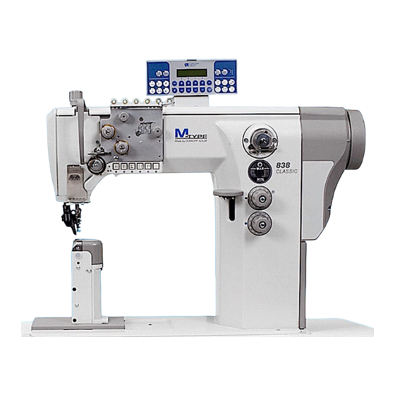
- Page 1 Service Instructions...
- Page 2 All rights reserved. Property of Dürkopp Adler AG and copyrighted. Reproduction or publication of the content in any manner, even in extracts, without prior written permission of Dürkopp Adler AG, is prohibited. Dürkopp Adler AG - 2015 Copyright ©...
- Page 3 Introduction This service booklet contains the instructions for setting the sewing machine head mechanisms. The directions for putting the machine into operation and for setting the positioning drive are contained in another publication. The service booklet is common for all subclasses of the machine and contains also the instructions for setting optional accessories of the machine, if this is necessary owing to their complexity.
- Page 4 General safety instructions The non-observance of the following safety instructions can cause bodily injuries or damages to the machine. 1. The machine must only be commissioned in full knowledge of the instruction book and operated by persons with appropriate training. 2.
-
Page 5: Table Of Contents
Index Page Service Instructions for the Class 838 (Edition 09.2015) General Setting gauges ..........Adjusting the handwheel . - Page 6 Index Page Electronic control and sewing machine drive - positioning motor ....Terminals to PCB connections - electromagnetic variant ..... . . Terminals to PCB connections - pneumatic variant .
-
Page 7: General
General These service instructions describe the adjustments that can be made to the class 838 special sewing machine. CAUTION! The operations described in these service instructions may only be carried out by qualified staff or other appropriately trained persons! Caution: Risk of injury! Turn the main switch off for repair, conversion and maintenance work and separate the machine from the pneumatic supply line. -
Page 8: Adjusting The Handwheel
Adjusting the handwheel Rule: The handwheel (4) is labelled with degree numbers. Certain adjustments are made with these marked handwheel positions. – Turn the handwheel until the degree value specified in the instructions is aligned with the pointer (3). – Proceed with the adjustment described. -
Page 9: Sewing Machine With Direct Drive
1.2.2 Sewing machine with direct drive – Unscrew three fixing screws on the hand wheel (5) and remove it. – Put the needle in the upper dead point and insert the setting pin (2), which is a part of the sewing machine accessories and which is fixed on the oil tray bottom side, into the crank head. -
Page 10: Bottom Feed
Bottom feed Basic setting for stitch adjustment and stitch length limit Rule: 1. When setting the stitch length at “0”, the stitch regulator gear should have as little play (clearance) as possible when you press down on the bartacking lever. 2. -
Page 11: Stitch Uniformity For Forwards And Reverse Stitching
Stitch uniformity for forwards and reverse stitching Rule: 1. When making a rough-scale adjustment to the stitch regulator gear, the machine should not feed when the stitch length is set to “0”. 2. When making a fine-scale adjustment to the stitch regulator gear, the forwards and reverse stitch lengths should only deviate in value by a half stitch. -
Page 12: Adjusting The Levers On The Rear Feed Shaft
Adjusting the levers on the rear feed shaft Rule: When setting the stitch length" 0“, the feed clutch should be in the middle range of the work limit settings. – Set the stitch length to “0”. – Loosen screw (1). –... -
Page 13: Position Of The Eccentric Tappet For The Feed Movement
Position of the eccentric tappet for the feed movement Rule: When the handwheel pointer indicates “355” degrees, the feed lever (1) should not move when the bartacking lever is pressed down. – Turn the handwheel so that the pointer indicates “355“. –... -
Page 14: Position Of The Eccentric Tappet And The Feed Dog Stroke
Position of the eccentric tappet and the feed dog stroke Rule: When the handwheel pointer indicates “239” on the scale, a settings pin inserted into the eccentric tappet should be flush with the ridge on the crankshaft (4). – Turn the handwheel so that the pointer indicates “239”. Loosen screws (1). -
Page 15: Switching Over The Feed Clutch
Switching over the feed clutch Rule: The clutch should be switched over when it is motionless (i.e., when it is in the dead centre point of its pendulum motion). – Loosen the screws (1) on the eccentric tappet (2). – Turn the eccentric tappet (2) so that the dash is aligned with the other dash (3). -
Page 16: Position Of The Eccentric Tappet For The Switch Over Of The Feed Clutch
Position of the eccentric tappet for the switch over of the feed clutch Rule: When the handwheel pointer indicates “305” on the scale, the dash (1) on the eccentric tappet should be lined up with the lower dash (2) on the V-shaped push rod. -
Page 17: Checking The Switch Over Of The Feed Clutch
Checking the switch over of the feed clutch Rule: The feed clutch should be switched over when it is motionless (i.e., when it is in the dead centre point of its pendulum motion). This can be detected from the rotational direction of the belt pulley (1) in front of and behind the dead centre point. -
Page 18: Feed Dog
Feed dog Rules: 1. The height (A) that the feed dog (1) is above the throat plate must be appropriate for the thickness and toughness of the material. 2. In its highest position (A), the feed dog should be 1 mm over the throat plate insert. -
Page 19: 2.10 Balance Weight
2.10 Balance weight Rule: The balance weight (1) has to be positioned in a way that, with the handwheel in position “210°”, an Allen key (3) stuck in stands parallel to the bed plate (2). – Loosen the screws on the balance weight (1). –... - Page 20 Notes:...
-
Page 21: Top Feed
Top feed Positioning the needle holder for single-needle sewing machines Rule: The needle holder positioning is carried out according to the following table and depends on the thickness of the needle. Angularity of the needle holder Needle width/ Nm 120 - 160 180 - 200 –... -
Page 22: Needle Bar Holder
Needle bar holder Rules: 1. The needle bar should be adjusted so that it is flush with the presser foot bar. 2. The post bed feed should be: 2.1 for the single-needle machine, it should be set so that the axis of the needle is moved (A) = 0.1mm to the left to the middle of the stitch hole. - Page 23 Fig. 1 Fig. 2 – Loosen screw (2) and the two screws (3). Move the post bed feed (4) so that either rule 2.1 is met (A = 0.1 mm) according to Figure 1, or rule 2.2 according to Figure 2.
-
Page 24: Top Roller
Top roller Rules: 1. The seating area on the top roller holder should be aligned at a right angle to the machine’s longitudinal axis (centre-line). A clearance of (A) = 0 mm should exist between the top roller and the throat plate. 2. -
Page 25: Lifting The Top Roller
Lifting the top roller Rules: 1. The top roller should have a 5.4 to 5.6 mm lift from the hand lever. 2. The top roller should have an 11.5 to 12.5 mm (automatic) lift with the pneumatic cylinder. – Loosen screws (1). Move the hand lever (2) into the position shown. -
Page 26: Fabric Holder For Double Needle Sewing Machines
Fabric holder for double needle sewing machines Rules: 1. The fabric holder should touch the sewing material without exerting any pressure on it. 2. The fabric holder should be positioned in sewing direction and laterally on the edges of the stitch holes. –... -
Page 27: Setting The Needle Bar And The Hook Hook Height
Setting the needle bar and the hook Hook height Standard checking The distance A should be 1.7 up to 1.8 mm. – Loosen screw (1). – Loosen screws (2), shift the hook at the distance (A) and tighten the screws (2). –... -
Page 28: Needle Bar Height, Play Of Needle To Hook Tip, Loop Stroke
Needle bar height, play of needle to hook tip, loop stroke Rule: When the handwheel pointer indicates “205” degrees (2.5 mm loop stroke), the hook tip should stand at the needle axis at the stitch length 0. Length (A) = 1.5 mm, clearance gap (B) = 0.02 to 0.1 mm. –... -
Page 29: Hook Tip Guard And Loop Former
Hook tip guard and loop former Rule: 1. The loop former (1) with the single needle machines should be set to have a distance to the needle thinkness of (A) = 0.1 to 0.2 mm. 2. The guard plate of the hook (3) should prevent a contact between the needle and the hook tip (4). -
Page 30: Bobbin Housing Release
Bobbin housing release Rules: 1. When the retention pin (1) in inserted into the lifting cam, the handwheel indicator should point to: - From “305” to “315” for the right hook column - from “42” to “52” for the left hook column. 2. -
Page 31: Hook Lubrication
Hook lubrication Rule: 1. Between the lubricating fitting (2) and the hook should be a distance of (A) = 0.3 mm. 2. The setting screw (3) of the lubrication should proceed 0.5 mm out of the lubricating fitting. – Loosen screw (1), set the height of the lubricating fitting (2) to the distance measure (A) according to rule 1 and tighten screw (1). -
Page 32: Thread Setting
Thread setting Thread regulator, check spring, bolt for the thread lever mechanism Rules: 1. The rightmost edge of the thread regulator (1) should align with the number 4 on the scale. 2. The check spring (5) should be set to the distance measure of (A) = 10 to 12 mm. -
Page 33: Bobbin Winder
Bobbin winder Rule: 1. When the bobbin winder is switched off, the distance between bobbin winder wheel and belt pulley should be (A) = 0.8 mm. 2. The winding procedure should stop automatically, when the bobbin is filled up to 0.5 mm underneath the the bobbin edge. –... -
Page 34: Thread Cutter
Thread cutter Thread cutter height, position of the counter knife Standard checking 1. The distance measure between the thread-pulling knife (5) and the hook should be (A) = 0.2 mm. 2. The distance measure between the counter knife (6) and the thread-pulling knife (5) should be (B) = 0.3 to 0.5 mm. -
Page 35: Starting Position For The Thread Pulling Knife
Starting position of the thread-pulling knife Rule: When the roller (1) is in the highest point of the control cam (2) the end of the thread-pulling knife (3) should overrun the blade of the counter knife (4) of 0.5-1 mm. –... -
Page 36: Control Cam
Control cam Rule: 1. There should be a clearance distance (A) = 0.05 to 0.1 mm between the highest point on the control cam (1) and the roller (2). 2. The threads should be separate when the pointer on the handwheel points from “40”... -
Page 37: Bobbin Thread Clamp
Bobbin thread clamp Rule: The clamping force of the spring (1) should not be set higher than needed. It should just be able to pull out the lower thread from the hook. – Sew and cut the threads. – Using a screwdriver (2), inspect the thread according the illustration. - Page 38 Electronic control and sewing machine drive - positioning motor All operating instructions and parameter sheets are available at the manufacturers´ websites (see www.efka.net, www.duerkopp-adler.com, www.hohsing.com, etc.). Selected instructions concerning the control and drive setting needed for the operators are included in the Operating instructions. Selected instructions needed for the technician to set the drive are included in the Operating instructions.
- Page 39 Terminals to PCB connections - electromagnetic variant Description of DA178-2 (9850 688001) switchboard connection X11 - main connection cable to control unit X12 - keypad (Taster) X13 - terminals for solenoid connection 1,2,3 – supply voltage +24V 4 - VR (backtacking) 5 - FL (foot lifting) 6 - FS (thread tensioner) 7 - STL OUT (half stitch)
- Page 40 Terminals to PCB connections - pneumatic variant Description of DA199_2 (9850 838000) switchboard X11 - 37-pole connector (to control box) X12 - thread tensioner valve X13 - secondary thread tensioner valve X14 - bartacking valve X15 - sewing foot valve X16 - keypad X17 - bobbin thread monitor X18 - light barrier...
- Page 41 DÜRKOPP ADLER AG Potsdamer Str. 190 33719 Bielefeld Germany Phone +49 (0) 521 925 00 E-Mail: service@duerkopp-adler.com www.duerkopp-adler.com...
Need help?
Do you have a question about the M-Type 838-180122-M and is the answer not in the manual?
Questions and answers