Advertisement
Advertisement
Table of Contents

Related Manuals for Bodyworx E1000


Summary of Contents for Bodyworx E1000
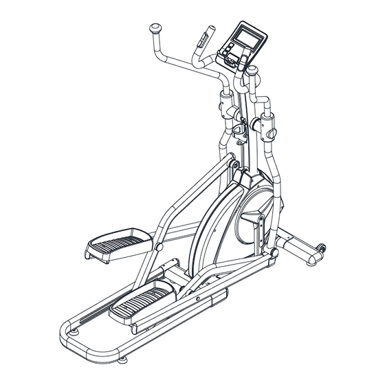
- Page 1 E1000 Power Stride 20 Elliptical...
-
Page 2: Table Of Contents
Table Of Contents …………………………………………….. Product Safety ……………………...………….. Part Drawing & Contents ………………………………………….. Hardware & Tools …………………………………….…………….. Assembly ………………………………….…………….. Adjustments ……………..………… Trouble Shooting & Maintenance ………………………………………..…………. Computer ……………………………………..……………. Warm Up ……………………………………..…………….. Part List ……………………………………………. Exploded View ……………………………………..……………. Warranty... -
Page 3: Product Safety
Product Safety Basic precautions should always be followed, including the following safety instructions when using this equipment: Read all instructions before using this equipment. Read all the instructions in this manual and do warm up exercises before using this equipment. Before exercise, in order to avoid injuring your muscles, warm-up exercise for every muscle group is highly recommended. -
Page 4: Part Drawing & Contents
Part Drawing & Contents Box A A13/A14 Hand Pulse Main Frame 1Set Handlebar 1Set Front Stabilizer 1Set Handrail L/R 2Set Computer C17/C18 C07/C08 C12/C28 Handrail Arm Upright Post Decorative Cover 2Set Decorative Cover 1Set Foot Pedal 1Set Water Bottle Lubricant Box B A03/A04 A05/A06... -
Page 5: Hardware & Tools
Hardware & Tools B33(1) B19(2) B30(3) B23(4) Curve Washer Washer ∅5/16”x20x2.0t Washer ∅3/8”x20x2.0t ∅8x20x1.5t Bolt M6x15mm B28(5) B21(6) B43(7) B32(9) Hexagon Head Bolt Bolt M8x50mm Screw M5x16mm 10PC Dome Nut 3/8” M8x16mm B40(10) B18(11) B29(12) Bolt M8x25mm Bolt 3/8”x2-1/2" Nut M8 (13) (14) Hex Tool With Phillips... -
Page 6: Assembly
Assembly 1. Front Stabilizer Installation Place a block of wood to raise the Main Frame (A01) for easier to install the Front Stabilizer (A16). Position the Front Stabilizer (A16) in front of Main Frame (A01) and align bolt holes. Attach the Front Stabilizer (A16) onto the front curve of the Main Frame (A01) with Two 3/8”x2-1/2"... - Page 7 Assembly 4. Left and Right Foot Bar Sets Installation Insert the Right Handrail Arm (A04) all the way onto the horizontal axle of the Upright Post (A02) and secure the Right Handrail Arm (A04) in position with One M8x16mm Hexagon Head Bolt (B32) and One 5/16"x20x2.0T Washer (B33).
- Page 8 Assembly Install Three M8x45 Nut Caps (C11) onto One M8 Nylon Nut (B29) and Two M8x16mm Hexagon Head Bolts (B32). Repeat above steps to install Left Handrail Arm (A03) onto the horizontal axle of the Front Post (A02) and Left Rotate Bar (A07) onto the Crank (A11) axle. CORRECT INCORRECT NOTE: Please fully tighten M8x20 Bolts (B14) with the Hex Tool with Phillips Screwdriver provided in Step 2.
- Page 9 Assembly 5. U Shape Guide Rail Installation Place a block of wood to raise the Main Frame (A01) for easier to install the U Shape Guide Rail (A12). Remove Four M8x92mm Bolts (B16), Eight 8x20x1.5T Curve Washer (B20) and Four M8 Nylon Nut (B29) from the U Shape Guide Rail (A12).
- Page 10 Assembly 8. Hand Pulse Handlebar Installation Insert the Sensor Wire I (D04) from the Upright Post (A02) into the hole on the Hand Pulse Handlebar (A15) and then pull it out from the Hand Pulse Handlebar (A15). Attach the Hand Pulse Handlebar (A15) onto the Upright Post (A02) with Two M8x25mm Bolts (B40).
- Page 11 Assembly 11. Foot Pedal Installation Align the Right Foot Pedal and Left Foot Pedal (C12, C28) and fit to Right Foot Bar and Left Foot Bar (A05, A06). Secure and tighten firmly with Four M6x15mm Bolts (B23). Slide the Foot Pedal Plug (C33) into the bolt holes of the foot pedal (C12, C28). [Tighten bolts with the M4 Allen Key provided.] 12.
-
Page 12: Adjustments
Adjustments Adjustments Adjusting the Adjustable Leveler Turn the adjustable leveler on the Front Stabilizer, Main Frame, or U Shape Guide Rail as needed to level the elliptical trainer. The elliptical trainer has to be leveled to prevent from wobble or shaking during the exercise. -
Page 13: Trouble Shooting & Maintenance
Trouble Shooting & Maintenance Trouble Shooting Computer not working correctly Check to make sure the computer cable is connected securely. The elliptical trainer wobbles when in use Turn the adjustable leveler on the front stabilizer, main frame, or U shape rail as needed to level the elliptical trainer. - Page 14 Owner’s Manual of Computer The monitor is designed for programmable magnetic bike and elliptical trainer and introduced with the following categories: Key Functions Displays Operating Ranges Notice Before Exercise Operation Instructions ● Key Functions There are total 6 keys including UP, DOWN, RESET, START/STOP, RECOVERY, and MODE.
- Page 15 C. Loading Profiles: There are 20 columns of loading bars, and 8 bars in each column. Each column represents 0.1 km workout (without the change of TIME value), and each bar represents 2 levels of loading. D. TIME Display: Indicates the TIME displayed. Fenster 1 Window 1 E.
- Page 16 H. CALORIES Display: Indicates the value of CALORIES. Fenster 5 Window 5 I. DISTANCE Display: Indicates the value of DISTANCE. Fenster 6 Window 6 J. PULSE Display: Indicates the value of PULSE. Window 7 ● Operating Ranges Display Exercise Data: TIME Display range 0:00~99:99 ;...
- Page 17 Program Selection: There are 19 programs with 1 Manual Program, 12 Preset Program, 4 Heart Rate Control Program, 1 User Setting Program, 1 Watt Control Program, and 1 Pulse Recovery Measuring. C. Program Graph: Each graph shown is the profile of the loading in each interval (column). With the value of km counting up, each interval is 0.1 km that all the columns make up 2 km.
- Page 18 2. Press UP or DOWN to preset TIME, DISTANCE, CALORIES, PULSE and press MODE to confirm. 3. Press START/STOP keys to start workout. Press UP or DOWN to adjust load level. 4. Press START/STOP keys to pause workout. Press RESET to reverse to main menu.
- Page 19 D. H.R.C. Mode: 1. Press UP or DOWN to select workout program, choose H.R.C. and press Mode to enter. 2. Press UP or DOWN to preset user age. 3. Press UP or DOWN to select 55%, 75%, 90%, or TAG (TARGET H.R.) (default:100).
-
Page 20: Computer
F. Recovery: Monitor heart rate recovery status. 1. User must be holding the handgrip. When the pulse value is displayed on the computer, press on the RECOVERY key. 2. TIME shows “0:60” (seconds) and count down. 3. Computer will show F1 to F6 after count down to 0 to test heart rate recovery status. -
Page 21: Warm Up
Warm Up Quadriceps Stretch With one hand against a wall for balance, reach behind you and pull your right foot up. Bring your heel as close to your buttocks as possible. Hold for 15 counts and repeat with left foot up. Inner Thigh Stretch Sit with the soles of your feet together with your knees pointing outward. -
Page 22: Part List
Part List Description Qty No. Description Qty No. Description A01 Welded, Main Frame B21 Screw M5x16mm 22 C17 Left Handrail Arm Decorative Cover A02 Welded, Upright Post B22 Cap Nut 3/8'' C18 Right Handrail Arm Decorative Cover A03 Welded, Left Handrail Arm B23 Bolt M6x15mm C19 Belt Pulley A04 Welded, Right Handrail Arm... -
Page 23: Exploded View
Exploded View... - Page 24 Model No: E1000 To register your warranty, please go to www.gpisports.com.au Distributed Exclusively by: GPI Sports & Fitness 275 Wellington Road Mulgrave, VIC, 3170 Australia.
Need help?
Do you have a question about the E1000 and is the answer not in the manual?
Questions and answers