
Related Manuals for Bodyworx E711


Summary of Contents for Bodyworx E711
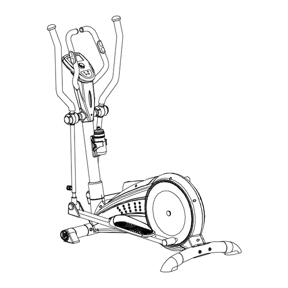
- Page 1 Rear Drive Elliptical BODY WORX BODY WORX Model No: E711 Retain this owner’s manual for future reference Read and follow all instructions in this owner’s manual Version A...
-
Page 2: Safety Instructions
Safety Instructions • To ensure the best safety of the exerciser, regularly check on damage and worn parts. suitable, non-slip mat under the exerciser. • If you pass on this exerciser to another person or if you allow • The general rush is that exercisers and training devices another person to use it, make sure that that person is familiar are not toys. -
Page 3: Exploded Drawing
Exploded drawing:... -
Page 4: Checking List
Checking list: &... -
Page 5: Part List
Part list: Part No. Description Q’ty Part No. Description Q’ty Main frame Foam (HDR) D30*5T*530L Front stabilizer Foam (HDR) D23*5T*680L Square neck bolt M8*1.25*93L Mushroom cap D1 1/4”*45L Adjustable foot cap Spring D3*D19*67L Left foot cap Tension cable D1.5*640L Right foot cap Bolt M6*1.0*15L Curved washer D22*D8.5*1.5T Allen bolt M8*1.25*50L... -
Page 6: Assembly Drawing
Assembly drawing: Step 1 M8*1.25*95L D22*D8.5*1.5T M8*1.25*93L D22*D8.5*1.5T D22*D8.5*1.5T D15.4*D8.2*2T D15.4*D8.2*2T M8*1.25*15L M8*1.25*15L STEP-1 1) Assemble the front stabilizer (2) to the main frame (1) by the square neck bolt (3), the curved washer (6), the spring washer (7) and the domed nut (8). 2) Assemble the rear stabilizer (19) to the main frame (1) by the curved washer (6), the spring washer (7), the domed nut (8) and the Allen bolt (14). - Page 7 Step 2 M6*1*45L D14*D6.5*0.8T D40*M6*12 STEP-2 1) Assemble the pedals (21L&21R) to the supporting tube for pedals (11) by the flat washer (73), the square neck bolt (20) and the club knob (77). 2) The user could adjust the pedals in 3 different positions.
- Page 8 Step 3 1) Assemble the handlebar post cover (49) to the handlebar post (10) shown as fig. a. 2) Connect the upper computer cable (29) with the lower computer cable (30) shown as fig. b. 3) Assemble the handlebar post (10) to the main frame (1) by the curved washer (6), the spring washer (7) and the Allen bolt (9) shown as fig.
- Page 9 Step 4 STEP-4 1) Insert the upper computer cable (29) into the computer (64). And then through the handlebar pulse cable attached to the computer out of the holes on the handlebar post (10) 2) Fix the computer(64) to the handlebar post (10) by bolt (76) 3) Plug the adaptor (78) and then turn on the computer.
- Page 10 Step 5 M8*1.25*100L D22*D8.5*1.5T D22*D8.5*1.5T D15.4*D8.2*2T M8*1.25*8T STEP-5 1) Assemble the fixed handle bar (72L&72R) to the handlebar post (10) by the curved washer (6), the spring washer (7), the Allen bolt (17) and the Nylon nut (18) 2) Connect the handle pulse cable(65) with the handle pulse cable attached to the computer shown as fig..
- Page 11 Step 6 1) Assemble the front computer bracket (68) and the rear computer bracket (67) to the handlebar post (10) by the screw (90) and the screw (91). 2) Assemble the bottle holder (104) to the handlebar post (10) by the bolt (103). 3) Assemble the bottle (105) to the bottle holder (104).
-
Page 12: Button Functions
INSTRUCTION MANUAL OF SM7690-71 【BUTTON FUNCTIONS】 To make upward adjustment to each function data or increase training resistance. DOWN To make downward adjustment to each function data or decrease training resistance. MODE To confirm all setting. STAR/STOP To start or stop workout. RESET To reset current setting and have the monitor switch to initial training mode for selection. - Page 13 In the setting mode (Figure 10), press ▲ or ▼ key to adjust M (Manual), P (Program), ♥ (HRC), W (Watt), and U (User) sequentially in circulation order. Figure 10 Press ▲ or ▼ key allows user to have MANUAL (Figure 10) → PROGRAM (Figure 11) → HRC (Figure 12) → WATT (Figure 13) →...
- Page 14 PROGRAM SETTING: Press ▲ or ▼ key to select one of the 12 PROGRAMS like PROGRAM P01, P02, P03, P04... P12. Corresponding graphics will show flashing texts (Figure 21) on LCD. Figure 21 When a PROGRAM is chosen, the value will be shown in flashing text in the LEVEL column and ready for the adjustment to be determined.
- Page 15 (9) When WATT (Figure 34) is selected, the WATT value will be shown in flashing text waiting to be adjusted. Default = 120 will be shown on LCD (Figure 35) User can press ▲ or ▼ to set WATT value. Press the MODE button for confirmation.
- Page 16 BODYWORX BODY WORX...
Need help?
Do you have a question about the E711 and is the answer not in the manual?
Questions and answers