Table of Contents
Advertisement
Quick Links
Advertisement
Table of Contents

Related Manuals for TYAN FT48A-B7070


Summary of Contents for TYAN FT48A-B7070
- Page 1 FT48A-B7070 Service Engineer’s Manual...
- Page 2 TYAN products including liability or ® warranties relating to fitness for a particular purpose or merchantability. TYAN retains the right to make changes to produce descriptions and/or specifications ® at any time, without notice. In no event will TYAN...
-
Page 3: Fcc Declaration
There will be danger of explosion if battery is incorrectly replaced. Replace only with the same or equivalent type recommended by manufacturer. Dispose of used battery according to manufacturer instructions and in accordance with your local regulations. http://www.tyan.com... -
Page 4: About This Manual
B7070 barebones system. This manual is intended for experienced users and integrators with hardware knowledge of personal computers. This manual consists of the following parts: Provides an introduction to the FT48A-B7070, barebones,standard parts list, external components, list Chapter 1: the key components of motherboard and provicd block diagram of the system . -
Page 5: Safety And Compliance Information
Safety and Compliance Information Before installing and using TYAN FT48A-B7070, take note of the following precautions: ·Read all instructions carefully. ·Do not place the unit on an unstable surface, cart, or stand. ·Do not block the slots and opening on the unit, which are provided for ventilation. -
Page 6: Safety Information
You must become familiar with the safety information in this guide before you install, operate, or service TYAN products. Symbols on Equipment Caution. This symbol indicates a potential hazard. -
Page 7: General Precautions
· Do not attempt to move a fully loaded rack. Remove equipment from the rack before moving it. · Do not attempt to move a rack on an incline that is greater than 10 degrees from the horizontal. http://www.tyan.com... - Page 8 This will reduce the risk of personal injury, fire, or damage to the equipment. The total rack load should not exceed 80 percent of the branch circuit rating. Consult the electrical authority having jurisdiction over your facility wiring and installation requirements. http://www.tyan.com...
- Page 9 TYAN, your authorized TYAN partner, or their agents. Equipment Modifications · Do not make mechanical modifications to the system. TYAN is not responsible for the regulatory compliance of TYAN equipment that has been modified.
- Page 10 – Liquid has been spilled on the product or an object has fallen into the product. – The product has been exposed to rain or water. – The product has been dropped or damaged. – The product does not operate normally when you follow the operating instructions. http://www.tyan.com...
-
Page 11: Table Of Contents
Table of Contents Chapter 1: Overview ................ 13 About the TYAN FT48A-B7070 ..........13 Product Models ............... 13 Features.................. 14 Standard Parts List ..............19 1.4.1 Box Contents ............... 19 1.4.2 Accessories ................. 20 1.5 System Front View ..............21 1.5.3... - Page 12 M7025 Power Distribution Board Features ......84 3.9.4 M7025 PDB Connector Pin Definition ......... 85 3.10 Replacing S7070 System Board ......... 87 Appendix I: Cable Connection Tables ........... 88 Appendix III: FRU Parts Table ............96 Appendix IV: Technical Support ............. 98 http://www.tyan.com...
-
Page 13: Chapter 1: Overview
®’ FT48A-B7070 uses TYAN s latest rack-mountable 4U chassis featuring a robust structure and a solid mechanical enclosure. All of this provides the FT48A-B7070 the power and flexibility to meet the needs of nearly any server application. Product Models Model... -
Page 14: Features
Features TYAN FT48AB7070 (B7070F48AW16HR) Form Factor 4U Rackmount Gross Weight 50 kg Chassis Model FT48A System Dimension (D x W x H) 27.5" x 16.8" x 6.9" (700 x 427 x 176mm) Motherboard S7070WGM2NR Board Dimension EEB, 12"x13" (305x330mm) Buttons... - Page 15 AST2400 iKVM Feature Mb/s MAC interface AST2300 iKVM Feature 10/100 Mb/s MAC interface Brand / ROM size AMI / 16MB User-configurable H/W monitoring / PXE boot BIOS Feature support / SMBIOS 2.5/PnP/Wake on LAN / ACPI 3.0/ACPI sleeping states S4,S5 http://www.tyan.com...
- Page 16 - 40° C ~ 70° C (-40° F ~ 158° F) Environment In/Non-operating 90%, non-condensing at 35° C Humidity RoHS RoHS 6/6 Compliant (1) FT48A-B7070 Barebone*systems will not Barebone display sensor information for the GPU/Coprocessor cards Package Contains Manual (1) Web User's manual...
- Page 17 Over temperature warning indicator / Fan & PSU fail LED indicator Others Watchdog timer support Onboard Chipset Onboard Aspeed AST2400 Server IPMI 2.0 compliant baseboard management Management AST2400 IPMI Feature controller (BMC) / Supports storage over IP and http://www.tyan.com...
- Page 18 - 40° C ~ 70° C (-40° F ~ 158° F) Environment In/Non-operating 90%, non-condensing at 35° C Humidity RoHS RoHS 6/6 Compliant (1) FT48A-B7070 w/NV Tesla-aware FW Barebone Barebone Package Contains Manual (1) Web User's manual Installation CD (1) TYAN installation CD...
-
Page 19: Standard Parts List
Standard Parts List This section describes FT48A-B7070 package contents and accessories. Open the box carefully and ensure that all components are present and undamaged. The product should arrive packaged as illustrated below. 1.4.1 Box Contents Component Description 4U Rackmount FT48A Chassis... -
Page 20: Accessories
If any items are missing or appear damaged, contact your retailer or browse to TYAN’s website for service: http://www.tyan.com ® The web site also provides information of other TYAN products, as well as FAQs, compatibility lists, BIOS settings, etc. ®... -
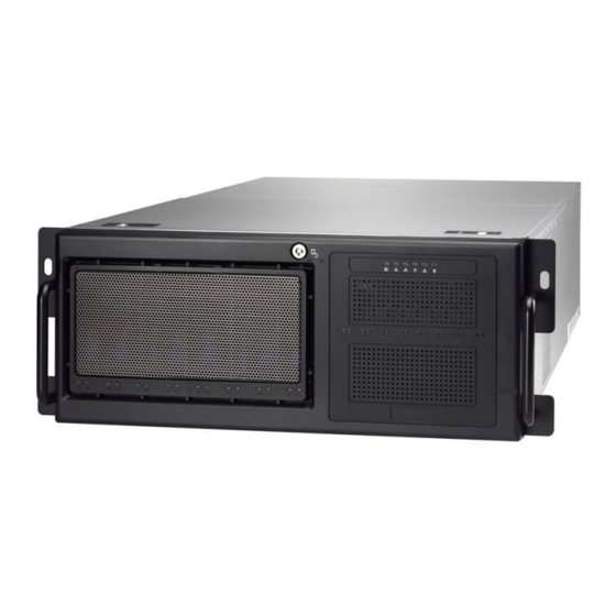
Page 21: 1.5.1 System Front View
1.5 System Front View The following views show you the product. 1.5.1 System Front View http://www.tyan.com... - Page 22 B7070F48AW16HR B7070F48AV4HR-N http://www.tyan.com...
- Page 23 LED Control Panel Power Button Reset Button NMI Button ID LED LAN2 LED LAN1 LED HDD LED Warning LED Power LED ID Button USB Ports http://www.tyan.com...
-
Page 24: System Rear View
1.5.2 System Rear View Thumb Screw for top Tray Thumb Screw for MB cover ID LED Button VGA Port LAN2 (shared with IPMI, i350)+ USB 2.0 Ports LAN1 (i350)+ USB 3.0 Ports Power Supply1 Power Supply2 Power Supply3 Expansion Slots http://www.tyan.com... -
Page 25: Led Definitions
ID LED will illuminate and the system is identified by a blue light. Users from remote site could also activate ID LED by interfacing with the IPMI. For further details on the IPMI software, please visit http://www.tyan.com for the latest AST2400 user guide. - Page 26 1Gbps LAN Link/Activity LED Scheme Left LED Right LED (Link/Activity) (Speed) No Link Link Green 10 Mbps Active Blinking Green Link Green Solid Green 100 Mbps Active Blinking Green Solid Green Link Green Solid Amber 1Gbps Active Blinking Green Solid Amber http://www.tyan.com...
-
Page 27: Motherboard (S7070) Layout
The board you receive may not look exactly like the above diagram. The DIMM slot numbers shown above can be used as a reference when reviewing the DIMM population guidelines shown later in the manual. For the latest board revision, please visit our web site at http://www.tyan.com. NOTE: FOR S7070GM2NR SKU, without SAS LSI2308 chip... -
Page 28: Jumpers/Connectors And Slots
13. IPMB Connector (IPMB1) 32. 4-pin Fan Connector(SYS_FAN3) 14. Front 2.0 USB Header(USB2_2) 33. 4-pin Fan Connector(SYS_FAN2) 15. TYAN Module Header 34. 4-pin Fan Connector (CPU0_FAN) 16. TYPE_A USB Header(A_USB1) 35. 4-pin Fan Connector ( SYS_FAN1) 17. Front 3.0 USB Header(USB3_2) 36. -
Page 29: Block Diagram
1.5.6 Block Diagram S7070 Block Diagram http://www.tyan.com... -
Page 30: Internal View
(8)3.5” HDD trays with (2) M1237F48-BP6-4-7055 SAS backplane ① (Pre-installed) M1018 Front Panel Board and (1) 5.25 inch media bays ② (8)2.5” HDD trays with M1244G70-BP6-8-B7070 System Fan Module ③ (6) 12038 hot-swap fan as pre-installed ④ System Main Board ⑤ (5) Expansion slots http://www.tyan.com... - Page 31 NOTE http://www.tyan.com...
-
Page 32: Chapter 2: Setting Up
Caution! To avoid damaging the motherboard and associated components, do not use torque force greater than 7kgf/cm (6.09 lb/in) on each mounting screw for motherboard installation. Do not apply power to the board if it has been damaged. http://www.tyan.com... -
Page 33: Precautions
Working on a system that is connected to a power supply can be extremely dangerous. Follow the guidelines below to avoid damage to FT48A-B7070 or injury to yourself. Ground yourself properly before removing the top cover of the system. -
Page 34: Installing Motherboard Components
2.1.1 Removing the Chassis Cover Follow these instructions to remove FT48A-B7070 chassis cover. Press the button on the front top cover and slide the cover off. Unscrew the thumb screw securing the rear cover then slide the rear top cover off. - Page 35 Remove the air duct from the chassis. http://www.tyan.com...
-
Page 36: Opening The Chassis Front Bezel
2.1.2 Opening the Chassis Front Bezel Insert the front bezel key (packed in a bag in the accessory box) and rotate the key 90 degrees counterclockwise to unlock the front bezel. Open the front bezel. http://www.tyan.com... -
Page 37: Installing The Cpu And Heat Sink
Follow the steps below on installing CPUs and CPU heatsinks. Locate the CPU0 and CPU1 sockets. . Pull the first and second levers slightly away from the socket and then push them to a fully open position. Push the CPU socket cover to a fully open position. http://www.tyan.com... - Page 38 Place the CPU into the socket and make sure that the gold arrow is located in the right direction. Take out the protection cap after installing the CPU. Close the CPU socket cover and press the levers down to secure the CPU. http://www.tyan.com...
- Page 39 Position the heatsink on top of the CPU and secure it with 4 screws. Repeat the procedures mentioned earlier to install the second CPU and heatsink. http://www.tyan.com...
-
Page 40: Installing The Memory
3. Align the memory module with the slot. When inserted properly, the memory slot locking levers lock automatically onto the indentations at the ends of the module. Follow the recommended memory population table to install the other memory modules. http://www.tyan.com... - Page 41 http://www.tyan.com...
- Page 42 3. Populate the same DIMM type in each channel, specifically - Use the same DIMM size - Use the same # of ranks per DIMM 4. Dual-rank DIMMs are recommended over single-rank DIMMs. http://www.tyan.com...
- Page 43 3. Populate the same DIMM type in each channel, specifically - Use the same DIMM size - Use the same # of ranks per DIMM 4. Dual-rank DIMMs are recommended over single-rank DIMMs. http://www.tyan.com...
- Page 44 Intel Xeon processor E5-2600v3 product families Support NOTE 1: 1DPC => One dimm per channel NOTE 2: 2DPC => Two dimm per channel Physical Ranks are used to calculate DIMM Capacity. Supported DRAM Densities are 4Gb, 8Gb. http://www.tyan.com...
-
Page 45: Installing The Pci-E Cards
2.1.5 Installing the PCI-E Cards FT48A-B7070 has five expansion slots. Only the PCI-E Gen.3 x16 slots can support GPU (Graphic Processing Unit) cards. 1.Slot #6: PCI-E G3x16 slot (x8 or x16 link) (f/ CPU0) 2.Slot #5: PCI-E G3x8 slot (x8 or x0 link) (f/ CPU0) ODM/OEM ... - Page 46 ® The FT48A-B7070 supports NVIDIA K40/K80 GPU cards. Follow these instructions was the example to install K80 GPU cards. Caution! The GPU power cable must avoid to be routed through the air inlet, because air inlet block will lead to GPU module overheated. This image illustrates the right power cable routing.
- Page 47 Install the GPU Air Duct and secure with 1 screw. Unscrew to take out the PCI brackets. Use 3 screws to secure the GPU bracket to the Nvidia K80 GPU Card. http://www.tyan.com...
- Page 48 Insert the GPU card into the PCIE slot. Connect the GPU power cable to the Nvidia K80 GPU Card. Screw the GPU card to the chassis. http://www.tyan.com...
-
Page 49: Installing Hard Drives
Installing Hard Drives The FT48A-B7070 supports up to eight 3.5” or 2.5” hard drives. Follow these instructions to install a hard drive. Install 3.5”or 2.5” HDD Press the locking lever latch and pull the locking lever open. Slide the HDD tray out. - Page 50 Option A: for 2.5” hard drives Located at the 3.5”/ 2.5” HDD tray. Place a 2.5” hard drive into the HDD tray. Use 4 screws to secure the HDD. http://www.tyan.com...
- Page 51 Located at the 3.5”/ 2.5” HDD tray. Place a 3.5” hard drive into the drive tray and use 4 screws to secure the HDD. Reinsert the HDD tray into the chassis and press the locking lever to secure the tray. http://www.tyan.com...
- Page 52 Install 2.5” HDD The FT48A-B7070 system is supporting (8) 2.5” hard drives. Follow these instructions to install a hard drive. NOTE: Only B7070F48AW16HR, B7070F48AV16HR has 2.5” HDD cage GPU SKU--B7070F48AV4HR-N without 2.5''HDD Cage 1. Press the locking lever latch and pull the latch open in the direction of arrow.
- Page 53 Place a hard drive into the drive tray. Use four screws to secure the HDD. Reinsert the HDD tray into the chassis. Press the locking lever to secure the hard drive. Repeat the same procedures to install other HDD trays. http://www.tyan.com...
-
Page 54: Installing Dvd Drive
Installing DVD Drive prepare DVD kit material Install the DVD Rail-L and Rail-R to the DVD device and secure with the packaged screws. Open the chassis front bezel, and check the location to insert the DVD device. http://www.tyan.com... - Page 55 Remove the DVD cover BKT. Install the DVD device into DVD location. DVD rail-R needs to be locked with the chassis hook. http://www.tyan.com...
- Page 56 Remove the J36 connector cable from the HDD BP-1. Insert the SATA cable on the motherboard J50 and route the cable along the side of the chassis. Connect the SATA cable to the DVD device. http://www.tyan.com...
- Page 57 10. Connect the DVD power Y cable to the HDD PWR cable. 11. Insert DVD power cable Y to the HDD BP-1 connector J36. http://www.tyan.com...
- Page 58 12. Connect the DVD PWR cable to the DVD device. 13. The DVD device has been successfully installed. http://www.tyan.com...
-
Page 59: Rack Mounting
A: Bracket for M6 screw--10 pcs B: M 6--10 pcs C: M 4-L5--16 pcs Installing the Inner Rails to the Unit Step1: Screw the mounting ears to each side of the FT48A-B7070 as shown using three M4-L5 screws (C) from the supplied screws kit. http://www.tyan.com... - Page 60 Step2: Secure the outer rails to the Server rack using 4 M6 screws (B) for each side. Secure the mounting brackets from the outside, not the inside of the server rack. http://www.tyan.com...
- Page 61 Rack Mounting the Server Step1: Draw out the middle rail to the latch position. Step2: Lift the unit and then insert the inner slide rails into the middle rails. Step3: Press the latch key and push the whole system in. http://www.tyan.com...
- Page 62 Step4: Secure the mounting ears of the unit to the rack using two small brackets (A) and M6 screws (B). http://www.tyan.com...
-
Page 63: Chapter 3: Replace Pre-Installed Components
FT48AB7070 server chassis, including the Motherboard, five small boards (M1018 Front Panel Board, M1237F48-BP6-4-7055 M1244G70-BP6-8-B7070 HDD Backplane, M1801F77-FB-FT48 Fan Board, M7025-PDB-NLS Power Distribution Board) System fan, ODD drive, PSU and etc. Disassembly Flowchart The following flowchart outlines the disassembly procedure. http://www.tyan.com... -
Page 64: Removing The Cover
Removing the Cover Before replacing any parts you must remove the chassis cover. Follow Chapter 2.1.1 to remove the cover of the FT48A-B7070. Replacing the System Fan Follow these instructions to replace the cooling fans in your system. 1. Take out the failed fan. -
Page 65: Replacing The Fan Board
Replacing the Fan Board Follow these instructions to replace the fan board 1. Remove all system fans from the fan cage 2. Unscrew the fan cage from the chassis. 3. Take out the fan cage from the chassis. http://www.tyan.com... - Page 66 4. Disconnect all cables from the fan board. 5. Unscrew the fan board to replace a new one 6. Assemble the fan cage and system fans back into the chassis following the steps described earlier in reverse. http://www.tyan.com...
-
Page 67: M1801F77 Fan Board Features
(1) 2 x 3-pin FAN Header, special for S7070 as FAN control 3.5.2 Fan Board LED Definitions FAN Status Green LED Red LED With Fan Speed RPM OK On Off Fan Failed or Without Fan Off On http://www.tyan.com... -
Page 68: M1801F77 Fan Board Connector Pin Definition
M1801F77 Fan Board Connector Pin Definition J1~J6: 4 pin Fan connector Definition Definition VDD+12V CLOCK PW1/PW2/PW3: Big 4 pin Power connector Definition Definition VDD+12V VCC+5V J8: fan control header Definition Definition TACH1 TACH6 TACH2 TACH3 TACH4 TACH5 PWM1 PWM2 PWM3 http://www.tyan.com... -
Page 69: Replacing The M1237F48 Sata/Sas Backplane
Chapter 3.4/3.5, then, follow these instructions to replace SATA/SAS backplane. Remove the HDD trays corresponding to the SAS/SATA backplane to be replaced from the FT48A-B7070 chassis. Disconnect all cables from the M1801F77-FB-FT48 to be replaced and remove the screw securing it. -
Page 70: M1237F48 Sata/Sas Backplane Features
4-pin Power connector(J36) 4-pin Power connector(J35) HDD Connector(J15) SAS only HDD Connector(J16) SAS only HDD Connector(J17) SAS only HDD Connector(J13) SAS only SGPIO Header(J18) FW Flash Header(J6) 29-pin SAS Connector(J1) 29-pin SAS Connector(J2) 29-pin SAS Connector(J4) 29-pin SAS Connector(J5) http://www.tyan.com... - Page 71 Definition Definition CPLD_JTAG_TCK CPLD_JTAG_TDO VDD_3P3_RUN CPLD_JTAG_TMS dummy pin dummy pin key pin CPLD_JTAG_TDI J18: SGPIO header Definition Definition FPIO_SCL SDATAIN FPIO_SDA SDATAOUT SAS_SIO_END_A Key pin SAS_SIO_CLK_A dummy pin HD_ERR_LED J35/J36: Big 4 pin Power connector Definition Definition VDD+12V VCC+5V http://www.tyan.com...
-
Page 72: Replacing The M1244G70-Bp6-8 Sata/Sas Backplane
Disconnect the power cable and SAS cable from backplane board. Then push aside the latch to release the backplane board unit. Slide the backplane unit out of the chassis. 3. Remove six screws securing the LED control board to the bracket. http://www.tyan.com... -
Page 73: M1244G70-Bp6-8-B7070 Sata/Sas Backplane Features
M1244G70-BP6-8-B7070 SATA/SAS Backplane Features Front View Form Factor 8-Layer PCB (1) To S7027GM3NR-LNV mini-SAS connector (1) To add-on card mini-SAS connector Integrated I/O (1) 4x2 pin Power connector (1) 5x2 K8 pin JTAG connector http://www.tyan.com... - Page 74 Rear View Form Factor 8-Layer PCB Integrated I/O (8) SAS HDD Connectors...
-
Page 75: M1244G70-Bp6-8-B7070 Connector Pin Definitions
3.7.2 M1244G70-BP6-8-B7070 Connector Pin Definitions Definition Definition +12V +12V +12V +12V J11 (CN8) Definition Definition CPLD_JTAG_TCK CPLD_JTAG_TDO VDD_3P3_RUN CPLD_JTAG_TMS CPLD_JTAG_TDI http://www.tyan.com... -
Page 76: Replacing The Front Panel Control Board
Replacing the Front Panel Control Board Follow these instructions to replace the M1018 LED control board. Disconnect the power cable and data cable from M1018. Push aside the latch and slide the LED control board unit out of the chassis. http://www.tyan.com... - Page 77 Remove three screws securing the LED control board to the bracket. Lift the LED control board free from the chassis. After replacement, insert the unit into the chassis following the above procedures in reverse. http://www.tyan.com...
-
Page 78: M1018 Led Control Board Features
3.8.1 M1018 LED Control Board Features Power Switch Warning LED Reset Switch Power LED NMI Switch ID Switch ID LED USB 2 LAN2 LED USB 1 LAN1 LED 2x14 pin header HDD LED 2x5 pin USB header http://www.tyan.com... -
Page 79: M1018 Led Control Board Connector Pin Definition
HD_LED- RESET+ RESET- Power LED+ Power LED- WLED+ WLED- Reserved Reserved EXT INT Voltages V5SB Reserved Power SW+ Power SW- LAN1 LED+ LAN1 LED+ LAN2 LED+ LAN2 LED+ Reserved Reserved ID LED-IN+ ID LED-IN- ID SW+ ID SW- Reserved http://www.tyan.com... -
Page 80: Replacing Power Supply And M7025 Pdb
Replacing Power Supply You need to disconnect the power supply first before replacing the power distribution board. Press the red button on the power supply and slide it out. After replacement new ones, insert the power supply back into the chassis. http://www.tyan.com... -
Page 81: Replacing M7025 Power Distribution Board
Disconnect the 8-pin power cable, PSMI cable on the motherboard. 2. Disconnect the 4-pin power, PSMI, SGPIO, Front Panel, Mini SAS Fan Control and USB Cables. Loosen the thumb screw and the screws on both sides of the chassis. And then pull down the bar. http://www.tyan.com... - Page 82 4. Pull down the bar to slide the motherboard tray out. You can find the power distribution board underneath the motherboard tray 5. Disconnect the cables on the PDB. http://www.tyan.com...
- Page 83 6. Locate the 12 screws on the PDB, then you can renew the board and fix it back follow the steps above in reverse. http://www.tyan.com...
-
Page 84: M7025 Power Distribution Board Features
Connectors (2) 2 x 4-pin Power Connectors (8) 2 x 2-pin Power Connectors (2) 1 x 5-pin Jumper for SMBus (2) 1 x 3-pin Jumper FCC Class B (DoC) Regulation European Community CE (DoC) http://www.tyan.com... -
Page 85: M7025 Pdb Connector Pin Definition
Board Definition Definition +12V PW5/16: 2×10-Pin Power Connector Definition Definition +12V +12V +12V +12V +12V +12V +12V +12V +12V +12V PW4/17: ATX 2×12-Pin Power Connector Definition Definition +3.3V +3.3V +3.3V -12V PS_ON PWR Good Reset 5VSB +12V +12V +3.3V http://www.tyan.com... - Page 86 VDD3.3V J9: Power Redundancy Select Jumper Definition Single_PSU RSVD NOTE: Pin 1-2 closed for PSU 2+0 or 2+1 (Default) Pin 2-3 closed for PSU 1+0 or 1+1 J10: PS_ON Enable/Disable Jumper Definition RSVD PSON_EN NOTE: Pin 1-2 closed (Default) http://www.tyan.com...
-
Page 87: Replacing S7070 System Board
Make sure you have disconnected all cables. 2. Unscrew the motherboard. 3. Carefully lift the motherboard from the tray. 4. Prepare a new motherboard and follow the steps described earlier in reverse order to reinstall the motherboard into the chassis. http://www.tyan.com... -
Page 88: Appendix I: Cable Connection Tables
3.5” HDD BP-2 → Mini-SAS Cable 3.5” HDD BP-2 → P/N: SATA0-3 422794600005 3.5” HDD BP-2 → 3.5” HDD BP-2 → Mini-SAS Cable-1 2.5”HDD BP → SAS0_3 P/N: SAS0 422797000003 Mini-SAS 2.5”HDD BP → Cable-2 P/N: SAS4_7 SAS1 422797000003 http://www.tyan.com... - Page 89 HDD BP PWR Cable-3 2.5” HDD BP → PW16 P/N: 422T45900008 5. FP Ctrl and USB Cable Front Panel Board (FPB) to S7070 MB Connect to S7070 MB Control Cable → P/N: FPIO1 422790900001 USB Cable → P/N: USB2_2 422790900002 http://www.tyan.com...
- Page 90 422T45900008 7. 2x12P, 2x10P PWR & PSMI Cable PDB Board to S7070 MB PDB Board Connect to S7070 MB 2x12P PWR Cable → P/N: 422T45900005 2x10P PWR Cable PW2,PW3,PWR_ → P/N: BTN1 422T45900006 PSMI Cable → P/N: PSIMI1 422788200004 http://www.tyan.com...
- Page 91 This section aims to help readers identify the locations of some specific FAN and Temp Sensors on the motherboard. A table of BIOS Temp sensor name explanation is also included for readers’ reference NOTE: The red dot indicates the sensor. http://www.tyan.com...
- Page 92 (rpm) Temp Sensor: PCH_Area_Temp, CPU1_MOS_Temp (RT31) CPU0_MOS_Temp(RT33). They detect the system temperature around. NOTE: The system temperature is measured in a scale defined by Intel, not in Fahrenheit or Celsius. BIOS Temp Sensor Name Explanation: http://www.tyan.com...
- Page 93 http://www.tyan.com...
- Page 94 Temperature of CPU1 DIMM C0 Slot CPU1_DIMM_C1 Temperature of CPU1 DIMM C1 Slot CPU1_DIMM_D0 Temperature of CPU1 DIMM D0 Slot CPU1_DIMM_D1 Temperature of CPU1 DIMM D1 Slot BIOS FAN Sensor Name Explanation CPU0_FAN Fan speed of CPU0_FAN CPU1_FAN Fan speed of CPU1_FAN http://www.tyan.com...
- Page 95 Fan speed of SYS_FAN_5 SYS_FAN_6 Fan speed of SYS_FAN_6 SYS_FAN_7 Fan speed of SYS_FAN_7 SYS_FAN_8 Fan speed of SYS_FAN_8 SYS_FAN_9 Fan speed of SYS_FAN_9 SYS_FAN_10 Fan speed of SYS_FAN_10 SYS_FAN_11 Fan speed of SYS_FAN_11 SYS_FAN_12 Fan speed of SYS_FAN_12 http://www.tyan.com...
-
Page 96: Appendix Iii: Fru Parts Table
1x Mini-SAS cable (to S8812 MB) 2.5’’ FRU-SO-0100 5411T5320002 Storage 1x power cable (for backplane) 4x 3.5” to 2.5’’ hot-swap HDD trays 1X 2.5" HDD Cage,FT48A-B7070 8X 2.5’’ HDD Tray 2.5’’ FRU-SO-0090 5411T5320001 1X M1244G70-BP6-8-B7070 1X M1244 BP BKT Tray Kit... - Page 97 MINI-SAS 36P/SATA 7PX4 180° ,L=550MM,FT48-B8812 TF-CABLE ASSY;SAS INTERNAL,SBU,30 Cable FRU-CS-0340 422T45900002 AWG,650 mm,SATA CABLE,SATA 7P*4/SATA 7P*4,FT48-B7055 TF-CABLE ASSY;SBU,MINI-SAS CCBL-0688 422797000003 CABLE,SHORT MINI-SAS 36P/ SHORT MINI-SAS 36P,L=800MM,TN70-B7016-X2 TF-CABLE ASSY;SAS INTERNAL,SBU,30 AWG,800 mm,MINI-SAS HD CABLE, SHORT FRU-CS-0200 422T51400002 MINI-SAS HD 36P/SHORT MINI-SAS 36P,GT62B-B7076 http://www.tyan.com...
-
Page 98: Appendix Iv: Technical Support
(which can have expensive consequences). If these options are not available for you then TYAN Computer Corporation can help. Besides designing innovative and quality products for over a decade, Tyan has continuously offered customers service beyond their expectations. - Page 99 Return Merchandise Authorization (RMA) number. The RMA number should be prominently displayed on the outside of the shipping carton and the package should be mailed prepaid. TYAN will pay to have the board shipped back to you ®...
Need help?
Do you have a question about the FT48A-B7070 and is the answer not in the manual?
Questions and answers