Table of Contents
Advertisement
Quick Links
Advertisement
Table of Contents

Subscribe to Our Youtube Channel
Related Manuals for TYAN FT83A-B7129


Summary of Contents for TYAN FT83A-B7129
- Page 1 FT83A-B7129 Service Engineer’s Manual...
- Page 2 TYAN products including liability or ® warranties relating to fitness for a particular purpose or merchantability. TYAN retains the right to make changes to produce descriptions and/or specifications at ® any time, without notice. In no event will TYAN...
- Page 3 This Class A digital apparatus complies with Canadian ICES-003. Cet appareil numérique de la Classe A est conforme à la norme NMB-003 du Canada. ● Notice for Europe (CE Mark) This product is in conformity with the Council Directive 2014/30/EU and 2014/35/EU. http://www.tyan.com...
- Page 4 Safety: IEC/EN 62368-1 This equipment is compliant with CB/LVD of Safety: IEC/EN 62368-1:2014. Warning Keep new and used batteries away from children. If the battery compartment does not close securely, stop using the product and keep it away from children. http://www.tyan.com...
- Page 5 Chapter2: Setting Up This chapter Covers procedures on installing the CPU, memory modules, add on card and hard drives. Give an overview about the FT83A-B7129 barebone from an overall angle. Chapter 3: Replacing the Pre-installed Components This chapter covers the removal and replacement procedures for pre-installed components.
- Page 6 Safety and Compliance Information Before installing and using TYAN FT83A-B7129, take note of the following precautions: ·Read all instructions carefully. ·Do not place the unit on an unstable surface, cart, or stand. ·Do not block the slots and opening on the unit, which are provided for ventilation.
- Page 7 You must become familiar with the safety information in this guide before you install, operate, or service TYAN products. Symbols on Equipment Caution. This symbol indicates a potential hazard.
- Page 8 · Do not attempt to move a fully loaded rack. Remove equipment from the rack before moving it. · Do not attempt to move a rack on an incline that is greater than 10 degrees from the horizontal. http://www.tyan.com...
- Page 9 This will reduce the risk of personal injury, fire, or damage to the equipment. The total rack load should not exceed 80 percent of the branch circuit rating. Consult the electrical authority having jurisdiction over your facility wiring and installation requirements. http://www.tyan.com...
- Page 10 TYAN, your authorized TYAN partner, or their agents. Equipment Modifications · Do not make mechanical modifications to the system. TYAN is not responsible for the regulatory compliance of TYAN equipment that has been modified.
- Page 11 – The product does not operate normally when you follow the operating instructions. Instructional safeguard requirement An instructional safeguard shall be provided to reduced the likelihood of unintentional contact with a moving part in accordance with Clause F.5 except that element 3 is optional. http://www.tyan.com...
-
Page 12: Table Of Contents
Table of Contents Chapter 1: Overview ..............14 About the TYAN FT83A-B7129 ........... 14 Product Models ..............14 Features................15 Standard Parts List .............. 21 1.4.1 Box Contents ..............21 1.4.2 Accessories ..............21 About the Product ..............22 1.5.1 System Front View ............ - Page 13 Appendix III: Fan and Temp Sensors ........214 Appendix IV: Cable Connection Tables ........220 Appendix V: Installing OCP Card ..........224 Appendix VI: FRU Parts Table ........... 226 Appendix VII: Glossary ............... 229 Appendix VIII: Technical Support ..........235 http://www.tyan.com...
-
Page 14: Chapter 1: Overview
IT environment but also offers a smooth path for future application usage. TYAN® also offers the FT83A-B7129 in a version that can support up to twelve (12) 2.5”/3.5” hot-swap SAS/SATA HDDs and (2) hot-swap 2.5" SATA HDD, (8) hot-swap 2.5"... -
Page 15: Features
Intel Xeon Scalable Processor, 3nd Supported CPU Series Gen Intel Xeon Scalable Processor Processor Thermal Design Power Max up to 270W (TDP) Wattage Up to 11.2/10.4 GT/s with Intel System Bus UltraPath Interconnect (UPI) support Intel C621A Chipset Switch IC (2) PLX PEX88096 http://www.tyan.com... - Page 16 8 Channels per CPU, 2 DIMM slots per Memory channel Channel Memory voltage 1.2V PCIE (11) PCI-E Gen4 x16 slot Pre-installed TYAN (2) M7129F83A-L16 riser card for Riser Card (2) PCI-E Gen4 x16 slot (left) (PCIE Gen4) Expansion Slots Pre-installed TYAN...
- Page 17 - 40° C ~ 70° C (-40° F ~ 158° F) In/Non-operating 90%, non-condensing at 35° C Operating Environment Humidity Please refer to the TYAN NVIDIA Note Compatibility List for the operating temperature while GPGPU deployed RoHS RoHS 6/6 Compliant...
- Page 18 80 plus Platinum Redundancy Q'ty / Socket Type (2) LGA4189 Intel Xeon Scalable Processor, 3nd Supported CPU Series Gen Intel Xeon Scalable Processor Processor Thermal Design Power Max up to 270W (TDP) Wattage System Bus Up to 11.2/10.4 GT/s with Intel http://www.tyan.com...
- Page 19 8 Channels per CPU, 2 DIMM slots per Memory channel Channel Memory voltage 1.2V PCIE (11) PCI-E Gen4 x16 slot Pre-installed TYAN (2) M7129F83A-L16 riser card for Riser Card (2) PCI-E Gen4 x16 slot (left) (PCIE Gen4) Expansion Slots Pre-installed TYAN...
- Page 20 - 40° C ~ 70° C (-40° F ~ 158° F) In/Non-operating 90%, non-condensing at 35° C Operating Environment Humidity Please refer to the TYAN NVIDIA Note Compatibility List for the operating temperature while GPGPU deployed RoHS RoHS 6/6 Compliant...
-
Page 21: Standard Parts List
Standard Parts List This section describes FT83A-B7129 package contents and accessories. Open the box carefully and ensure that all components are present and undamaged. The product should arrive packaged as illustrated below. 1.4.1 Box Contents FT83A-B7129 Chassis Kit 4U chassis*1 ... -
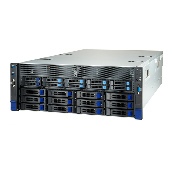
Page 22: About The Product
About the Product The following views show you the product. 1.5.1 System Front View http://www.tyan.com... - Page 23 DRIVE STATE Active LED (Green) Status LED (Red) Drive Present, No Active Solid on Drive Present with Active Blinking Don’t care Drive Failure Solid on Don’t care RAID Rebuild Blinking @4 Hz Don’t care Drive Locate Identifier Blinking @1 Hz http://www.tyan.com...
-
Page 24: System Rear View
1.5.2 System Rear View LAN1: from Realtek RTL8211E PHY for IPMI USB 3.1 x 2 OCP Card Area (OCP 3.0 LAN mezzanine slot) NOTE: 1. M7129F83A-RIO Rear IO board is pre-installed. http://www.tyan.com... -
Page 25: Led Definitions
AC present Only 12VSB on(PS off) or PS in Smart GREEN Redundant state Output ON and OK AMBER AC cord unplugged or AC power lost, with a second power supply in parallel still with AC input power. 2Hz Blink FW update mode GREEN http://www.tyan.com... -
Page 26: Internal View
M1313F83A-BP12E-12 HDD BP Board (pre-installed) System Fan with M7129F83A-Fan Board(pre-installed) Memory Slot CPU Socket M7129FT83A-IO PCIE Board 7~11 PCIE Gen4 x16 Slots (FH/FL, GPU#1 ~ GPU#5) PCIE Gen4 x16 Slots (FH/FL) 13~17 PCIE Gen4 x16 Slots (FH/FL, GPU#6 ~ GPU#10) http://www.tyan.com... -
Page 27: Chassis Dimensions
1.5.5 Chassis Dimensions http://www.tyan.com... -
Page 28: Chapter 2: Setting Up
Caution! To avoid damaging the motherboard and associated components, do not use torque force greater than 7kgf/cm (6.09 lb/in) on each mounting screw for motherboard installation. Do not apply power to the board if it has been damaged. http://www.tyan.com... -
Page 29: Precautions
Working on a system that is connected to a power supply can be extremely dangerous. Follow the guidelines below to avoid damage to FT83A-B7129 or injury to yourself. Ground yourself properly before removing the top cover of the system. -
Page 30: 2.1 Installing Motherboard Components
CPUs, memory modules and Add-on cards. 2.1.1 Removing the Chassis Cover Follow these instructions to remove FT83A-B7129 chassis cover. Remove the screw from the back side of the cover. Press the two latch to pull the back cover in the direction of the arrow to remove the top cover. - Page 31 Press the button to remove the back top cover from the chassis. http://www.tyan.com...
-
Page 32: Installing The Cpu, Heat Sink And Air Duct
Then install the carrier on the bottom of the heatsink and make sure the latches are snapped under the edge of the heatsink. Align and install the processor on the carrier. Make sure the gold arrow is located in the correct direction. Remove the CPU cover. http://www.tyan.com... - Page 33 NOTE: When disassembling the heatsink, loosen the screws in reverse order (4321). Repeat the procedures described earlier to install the second processor and heatsink. Place the air duct on top of the heatsink and screw it to the chassis. http://www.tyan.com...
-
Page 34: Installing The Memory
Press the memory slot locking levers in the direction of the arrows as shown in the following illustration. Align the memory module with the slot. When inserted properly, the memory slot locking levers lock automatically onto the indentations at the ends of the module. http://www.tyan.com... -
Page 35: Installing The Expansion Card (Pcie Board)
Installing the Expansion Card (PCIE Board) Follow these instructions to install the PCIE cards. Installing Expansion Cards Locate the PCIE Bracket. Insert the riser card to the PCIE x16 slot. Secure the card to the bracket with a screw. http://www.tyan.com... - Page 36 Installing GPU Card Follow the instructions to install the expansion cards with card brackets or card guides. Unscrew to remove the Linkbar. Locate the PCIE Gen.4 x16 slot on the motherboard. Unscrew to take out the dummy brackets. http://www.tyan.com...
- Page 37 Insert the GPU card into the PCIE Gen. 4 slot and screw the GPU card to the chassis. Connect the GPU PWR cable to the GPU card and motherboard. http://www.tyan.com...
- Page 38 Secure the GPU Bracket to the chassis with 4 screws. http://www.tyan.com...
-
Page 39: Installing Hard Drives
2.1.5 Installing Hard Drives The FT83A-B7129 supports ten 2.5” Hard Drives and twelve 3.5”/2.5” Hard Drives. Follow these instructions to install a hard drive. Installing 3.5”/2.5” HDD Press Locking lever to release the 3.5” HDD tray. Pull the 3.5”HDD tray out of the chassis. - Page 40 4. Reinsert the HDD tray into the chassis. http://www.tyan.com...
- Page 41 Always install the hard disk drive to the chassis after the chassis has been secured on the rack. Press the locking lever latch and pull the locking lever open. Slide the HDD tray out. Place the 2.5” HDD/SSD into the HDD tray and align the 2.5” HDD/SSD with its hole. http://www.tyan.com...
- Page 42 Turn over the HDD tray and secure the HDD/SSD to the tray using 4 screws. Reinsert the HDD tray into the chassis. Push to secure the locking lever until it clicks into place. http://www.tyan.com...
- Page 43 Follow these instructions to install a 2.5” HDD/SSD. Press the locking lever latch and pull the locking lever open. Slide the HDD tray out. Open the lock to place the 2.5” hard disk drive into the HDD tray. Push the HDD to the left. http://www.tyan.com...
- Page 44 Lock the tray lever to secure HDD. Reinsert the HDD tray into the chassis. Push to secure the locking lever until it clicks into place. http://www.tyan.com...
-
Page 45: Rack Mounting
19" rack. NOTE: Before mounting the TYAN TS83A-B7129 chassis in a rack, ensure that all internal components have been installed and that the unit has been fully tested. However, to make the installation easier, we suggest that you remove all HDD trays before you insert the chassis into the rack. - Page 46 Align the inner sliding rail on the side of the server, and push towards the arrow to secure the hooks. To install one screw onto chassis base each side. NOTE: Chassis base with or without screw hole design and the screw position for inner rail may be different for each chassis. http://www.tyan.com...
- Page 47 Detach inner rail from standoff Loosen screw both sides of the server. Pull the latch upward and remove the keyhole from standoff and slide inner rail forward to remove inner rail. http://www.tyan.com...
- Page 48 Secure the outer rails to the rack on each side. 2. Please repeat installation steps for the other side. Detach bracket from rack post to Release the outer rails from the rack on each side. 2. Please repeat the detach steps for the other side. http://www.tyan.com...
- Page 49 Pull the middle rail fully extended in lock position, ensure ball bearing retainer is located at the front of the middle rail. Horizontally insert the chassis into middle-outer rails. When hit a stop, please pull/push the blue release tab on the inner rails. Tighten chassis with shipping screws. http://www.tyan.com...
-
Page 50: Removing The Server From Rack
2.2.2 Removing the Server from Rack 1. Loosen shipping screws to pull out chassis. 2. Pull the disconnect tab forward to remove chassis at the full extension position. 3. Push tab to slide the middle rail back. http://www.tyan.com... -
Page 51: Chapter 3: Replacing Pre-Installed Components
This chapter explains how to replace the pre-installed components, including the S7129GMRE Motherboard, M7129F83A-L16 Riser Card, M1297T65-BP12E-12/ M1315F83A-BP12E-10 HDD Backplane Board, M7129F83A-IO IO board, M7129F83A-RIO Rear IO card, M7129F83A-FB Fan Board, System Fan and Power Supply, etc. Disassembly Flowchart The following flowchart outlines the disassembly procedure. http://www.tyan.com... -
Page 52: Removing The Cover
Removing the Cover Before replacing any parts you must remove the chassis cover. Follow Chapter 2.1.1 to remove the cover of FT83A-B7129. Replacing the Power Supply To replace the power supply follow these instructions. Press the tab as in the diagram from down to up. -
Page 53: Replacing The Front Panel Board
Unscrew to remove the front panel board module. Loosen three screws to take out the front panel board. Loosen two screws to take out the front panel board. Follow the steps described earlier in reverse order to reinstall the front panel board module. http://www.tyan.com... -
Page 54: Front Panel Board Features
PCB Dimensions: 40.00*18.00*1.6mm Form Factor Thickness: 1.6mm Layer: 4 layers power button with LED reset button Specifications ID button LED: ID LED (blue), Onboard HDD LED (green/Red), FAULT LED (Red/green/Blue), Power LED http://www.tyan.com... -
Page 55: Replacing The Usb Board
Unscrew to remove the front panel board module. Loosen three screws to take out the front panel board. Loosen two screws to take out the front panel board. Follow the steps described earlier in reverse order to reinstall the front panel board module. http://www.tyan.com... -
Page 56: Front Panel Board Features
3.6.1 Front Panel Board Features M1717T65-USB USB Board PCB Dimensions: 48.00*19.00*1.6mm Form Factor Thickness: 1.6mm Layer: 4 layers USB 3.0 Connectors Specifications 10*2PIN input Connector http://www.tyan.com... -
Page 57: Replacing The System Fan
Replacing the System Fan Follow these instructions to replace the system Fan. Take out the system fan. Press both sides of the fan cage as in the image. Open the fan cage. http://www.tyan.com... - Page 58 Take out the small fans. Replace a new fan. http://www.tyan.com...
-
Page 59: Replacing The Fan Board
Replacing the Fan Board Follow these instructions to replace the M7129F83A-FB Fan Board. Remove all Fan modules. Unscrew the fan cage. Lift up the fan cage. http://www.tyan.com... -
Page 60: Fan Board Features
Disconnect all cables from the Fan Board. 10. Unscrew to replace with a new Fan Board. Follow the steps in reverse order to reinstall the Fan Board. 3.8.1 Fan Board Features M7129F83A-FB Fan Board (Power) Specifications ort(FAN1-FAN8) (J10) http://www.tyan.com... -
Page 61: Replacing The Riser Board
Disconnect the from the M7129F83A-PCIE Board. Unscrew the release the buckle in the direction of the image to release the riser tray. Unscrew to release the M7129F83A-L16 riser card. Follow the steps described earlier in reverse order to reinstall the IO Bridge Bracket. http://www.tyan.com... -
Page 62: Riser Board Features
3.9.1 Riser Board Features Front View Rear View M7129F83A-L16 IO Bridge Board (2) Slim SAS Connector(J5/J6) Specifications (1) 2*2 Power Connector(PWR2) (1) PCIE Slot x16 (J3) http://www.tyan.com... -
Page 63: Replacing The Hdd Backplane Board
Unscrew the HDD BP Board and release it from the hook. Take out the HDD BP Board to replace with a new one. Follow the procedures described earlier in reverse order to reinstall the HDD BP Board and HDD cage. http://www.tyan.com... - Page 64 Disconnect all cables connected to the HDD BP Board. Unscrew the HDD BP Board from the chassis. Take out the HDD BP Board to replace with a new one. Follow the procedures described earlier in reverse order to reinstall the HDD BP Board and HDD cage. http://www.tyan.com...
-
Page 65: Hdd Backplane Board Features
(10) 2.5” SATA storage/(8) NVMe U.2SSD + (2) 2.5” SATA HDD (SATA 6G / NVMe 8G/s capability) (1) ATX 2*4P power connector(J9) Specifications (1) Mini SAS HD connector(J19) Overview (5) Slim SAS connector(J12,J5,J14,J13,J11) (1) 1*6P FAN connector(J17) (1) 2*10P TYAN FAN Header(Fan1,Fan2,Fan3,Fan4,Fan5,Fan6) http://www.tyan.com... - Page 66 M1297T65-BP12E-12 Front View Rear View Form Factor Dimension: 422.4*29.8mm 2x OCU Link Connector Input Specifications 3x Mini SAS HD Connector Input Overview 4x SGPIO Header 12x SATA HDD or 8 SATA HDD + 4x NVMe Output http://www.tyan.com...
-
Page 67: Connector Definition
Mini SAS HD Connector SATA4_7 Mini SAS HD Connector SATA8_11 Mini SAS HD Connector NVME01 SLIMSAS Connector NVME23 SLIMSAS Connector Power Connector SGPIO0 SGPIO Header for HDD0~7 SGPIO2 SGPIO Header for HDD8~11 SGPIO3 Reserved for AMD Platform SGPIO1 Reserved http://www.tyan.com... -
Page 68: Replacing Pcie Board
Disconnect all cables connected to the PCIE Board. Unscrew to lift up the PCIE Board Bracket (totally 19 screws). Replace the PCIE Board with a new one. Follow the steps described earlier in reverse order to reinstall the PCIE Board Bracket. http://www.tyan.com... -
Page 69: Pcie Board Features
3.11.1 PCIE Board Features Front View M7129F83A-IO PCIE Board Dual PCIE x24 lanes input and expansion to Specifications (1)PCIE x16 +(10) DW PCI-E x16 slots or (1)PCIE x16+ (20) PCIE x8 slots http://www.tyan.com... - Page 70 M7129F83A-IO Default PCIe Routing Topology (dual route) M7129F83A-IO Optional PCIe Routing Topology (Single Route) http://www.tyan.com...
-
Page 71: Replacing The Rear Io Board
M7129F83A-RIO Rear IO Board. Unscrew the Rear IO Bracket. Push both latches to pull the Rear IO Bracket out. Unscrew to remove the iron bracket. Follow the steps described earlier in reverse order to reinstall the Rear IO Bracket. http://www.tyan.com... -
Page 72: Rear Io Board Features
Rear IO Board Features Front View M7119FA77-RIO Rear IO Board (1)1G RJ-45 port for IPMI + (2)USB3.0 ports (1) FCI Board to board connector to Main board Specifications (1) OCP type A + (1)OCP type B connector for NIC OCP card http://www.tyan.com... -
Page 73: Replacing The Motherboard
3.13 Replacing the Motherboard After removing all of the aforementioned cables and components, follow these instructions to remove the motherboard from the chassis. Unscrew to remove the board. Disconnect all cables on the motherboard. http://www.tyan.com... - Page 74 Refer to 3.9 Replacing the IO Board to unscrew to lift up the Linkbar. Use a hex screwdriver and Phillips screwdriver to loosen screws. http://www.tyan.com...
- Page 75 Unscrew the motherboard to lift it up for replacement. http://www.tyan.com...
-
Page 76: Chapter 4: Motherboard Information
Caution! To avoid damaging the motherboard and associated components, do not use torque force greater than 7kgf/cm (6.09 lb/in) on each mounting screw for motherboard installation. Do not apply power to the board if it has been damaged. http://www.tyan.com... -
Page 77: Board Image
Board Image S7129 This picture is representative of the latest board revision available at the time of publishing. The board you receive may not look exactly like the above picture. http://www.tyan.com... -
Page 78: Block Diagram
Block Diagram S7129 Block Diagram http://www.tyan.com... -
Page 79: Motherboard Mechanical Drawing
Motherboard Mechanical Drawing http://www.tyan.com... -
Page 80: Board Parts, Jumpers And Connectors
The board you receive may not look exactly like the above diagram. The DIMM slot numbers shown above can be used as a reference when reviewing the DIMM population guidelines shown later in the manual. For the latest board revision, please visit our web site at http://www.tyan.com. http://www.tyan.com... - Page 81 3.PSU Connector (J2) 36. SlimSAS Connector for HDD BP (CN7) 4.XDP Connector (J7) 37. SlimSAS Connector for HDD BP (CN6) 5.TYAN Module Header (DBG_HD1) 38. SlimSAS Connector for HDD BP (CN5) 6.M.2 Connector (NGFF1) 39. Power Connector for Front Riser (J36) 7.RGMII/Rear USB B2B Connector (CN9)
- Page 82 Signal Signal BMC_COM1_DCD BMC_COM1_DRS BMC_COM1_RXD BMC_COM1_RTS BMC_COM1_TXD BMC_COM1_CTS BMC_COM1_DTR BMC_COM1_NRI HD_COM2: COM Port Header Signal Signal COM2_DCD COM2_DSR COM2_RXD COM2_RTS COM2_TXD COM2_CTS COM2_DTR COM2_NRI TYPEA_USB3: Vertical Type-A USB3.1 Connector Signal Signal USB DATA2- USB DATA2+ SSRX- SSRX+ SSTX- SSTX+ http://www.tyan.com...
- Page 83 RST_SW# FP_ID_LED_BTN_N INTRUDER# FPIO_TEMP_IN LAN2_ACTLED+ NMI_SW# LAN2_ACTLED- FPIO_VGA: Front Panel VGA Header Signal Signal CON_VGA_R CON_VGA_G CON_VGA_B CLK_33M CON_VGA_HS CON_VGA_CLK CON_VGA_VS J51: SATA_RAID_KEY (HW Key for Intel VROC – NVMe only) Signal Signal 2.21K to VCC3_AUX 2.21K to VCC3_AUX http://www.tyan.com...
- Page 84 PIN C4 TX1_P TX1_N PIN C5 PIN C6 PIN C7 PIN C8 TX3_P TX3_N PIN C9 PIN D1 VACT PIN D2 VMAN PIN D3 PIN D4 PIN D5 TX0_P TX0_N PIN D6 PIN D7 TX2_P PIN D8 TX2_N PIN D9 http://www.tyan.com...
- Page 85 DBG_HD1: TYAN Module Header Signal Signal P3V3 FRAME_N LAD0 LAD1 PLT_RST_N LAD2 LAD3 CLK_33M DBG_SERIRQ DBG_PRES_N VCC3_AUX TPM_ADDR_MB PCH_TPM_PP_EN J55: 8-pin Power Connector to HDD BP Signal Signal P12V_IN P12V_IN P12V_IN P12V_IN J47/J15: 8-pin Power Connector to PCIE Board Signal...
- Page 86 1-2 Closed: Normal 2-3 Closed: ME Recovery Mode J59: ESPI_LPC Jumper Pin1 Pin2 Pin3 PD_ESPI_EN ESPI_H_LPC_L VCC3_AUX 1-2 Closed: LPC Mode 2-3 Closed: ESPI Mode Jumper Legend OPEN - Jumper OFF Without jumper cover CLOSED - Jumper ON With jumper cover http://www.tyan.com...
-
Page 87: Thermal Interface Material
CPU lid (applying too much will actually reduce the cooling). NOTE: Always check with the manufacturer of the heat sink & processor to ensure that the thermal interface material is compatible with the processor and meets the manufacturer’s warranty requirements. http://www.tyan.com... -
Page 88: Tips On Installing Motherboard In Chassis
NOTE: Be especially careful to look for extra stand-offs. If there are any stand-offs present that are not aligned with a mounting hole on the motherboard, it will likely http://www.tyan.com... - Page 89 Some chassis include plastic studs instead of metal. Although the plastic studs are usable, MITAC recommends using metal studs with screws that will fasten the motherboard more securely in place. Below is a chart detailing what the most common motherboard studs look like and how they should be installed. http://www.tyan.com...
- Page 90 Before installing memory, ensure that the memory you have is compatible with the motherboard and processor. Check the TYAN Web site at http://www.tyan.com details of the type of memory recommended for your motherboard. This platform supports (16)+(16) DDR4 RDIMM/RDIMM 3DS/LRDIMM/ LRDIMM 3DS 3200/2933/2666/2400 ...
- Page 91 2. Use paired memory installation for max performance. 3. Populate the same DIMM type in each channel, specifically - Use the same DIMM size - Use the same # of ranks per DIMM 4. Always install with CPU0 Socket first. http://www.tyan.com...
- Page 92 √ √ CPU1_DIMM_ √ √ CPU1_DIMM_ √ CPU1_DIMM_ √ √ √ √ √ √ CPU1_DIMM_ √ √ CPU1_DIMM_ √ √ √ √ CPU1_DIMM_ √ √ CPU1_DIMM_ √ √ √ √ √ CPU1_DIMM_ √ √ CPU1_DIMM_ √ √ CPU1_DIMM_ √ http://www.tyan.com...
- Page 93 1 DCPMM per socket and 1 DCPMM per node case. DDR4 Type Capacity DRAM1 RDIMM 3DS RDIMM LRDIMM 3DS LRDIMM Any Capcity DRAM2 RDIMM 3DS RDIMM LRDIMM 3DS LRDIMM Any Capacity and Preferably, >=32GB DRAM3 RDIMM 16GB or 32GB DRAM4 RDIMM 3DS RDIMM LRDIMM Any Capacity http://www.tyan.com...
-
Page 94: Finishing Up
In the rare circumstance that you have experienced difficulty, you can find help by asking your vendor for assistance. If they are not available for assistance, please find setup information and documentation online at our website or by calling your vendor’s support line. http://www.tyan.com... -
Page 95: Chapter 5: Bios Setup
The table below shows how to navigate in the setup program using the keyboard. Function Left/Right Arrow Keys Change from one menu to the next Up/Down Arrow Keys Move between selections Enter Open highlighted section PgUp/PgDn Keys Change pages Change options Exit http://www.tyan.com... - Page 96 The following pages provide the details of BIOS menu. Please be noticed that the BIOS menu are continually changing due to the BIOS updating. The BIOS menu provided are the most updated ones when this manual is written. Please visit TYAN’s website at http://www.tyan.com for the information of BIOS updating. http://www.tyan.com...
-
Page 97: Main Menu
English / Simplified Chinese / Japanese System Date Set the Date. Use Tab to switch between Date elements. Default Ranges: Year: 1998-9999 Months: 1-12 Days: dependent on month System Time Set the Time. Use Tab to switch between Time elements. http://www.tyan.com... -
Page 98: Advanced Menu
Option ROM Dispatch Policy. S5 RTC Wake Settings Enable system to wake from S5 using RTC alarm. AST2600 Super IO Configuration System Super IO Chip Parameters Trusted Computing Trusted Computing Settings. ACPI Settings System ACPI Parameters. Power Management Power Management. http://www.tyan.com... - Page 99 Hardware Health Configuration Hardware health Configuration Parameters. NVDIMM ADR Configuration NVDIMM ADR Configuration. CPU Registration This item support INTEL CPU, sign the CPU will record current CPU. Once BIOS checked different with registered CPU, show WRNING message on POST screen. http://www.tyan.com...
- Page 100 Press <Enter> to select T1s Auth Configuration. iSCSI Configuration Configure the iSCSI parameters. VLAN Configuration (MAC: XXXXXXXXXXXX) VLAN Configuration (MAC: XXXXXXXXXXXX) MAC: XXXXXXXXXXXX --- IPV4 Network Configuration Configure network parameters. (MAC: XXXXXXXXXXXX) MAC: XXXXXXXXXXXX --- IPV6 Network Configuration Configure IPV6 network parameters. (MAC: XXXXXXXXXXXX) http://www.tyan.com...
- Page 101 On Board Mass Storage Controller Onboard Device has: UEFI [X]. Legacy Embedded ROM(s). VIDx8086; DIDxA252 @ s0|Bx0|Dx11|Fx5 Enabled / Disabled On Board Mass Storage Controller Onboard Device has: UEFI [X]. Legacy Embedded ROM(s). VIDx8086; DIDxA202 @ s0|Bx0|Dx17|Fx0 Enabled / Disabled http://www.tyan.com...
- Page 102 Enable or Disable Option ROM execution for selected Slot. Enabled / Disabled Slot #12 Bridge Device Device on Slot does not have an option ROM. Slot #13~15 Empty Enable or Disable Option ROM execution for selected Slot. Enabled / Disabled http://www.tyan.com...
- Page 103 Select 0-23. For example enter 3 for 3am and 15 for 3pm. Wake up minute Select 0-59 for Minute. Wake up second Select 0-59 for Second. When Wake system from S5 is set to [Dynamic Time] Wake up Minute increase http://www.tyan.com...
- Page 104 5.3.3 AST2600 Super IO Configuration Super IO Chip Read only. Serial Port 1 Configuration Set Parameters of Serial Port 1 (COMA). http://www.tyan.com...
- Page 105 / IO=3F8h; IRQ=3, 4, 5, 6, 7, 9, 10, 11, 12; / IO=2F8h; IRQ=3, 4, 5, 6, 7, 9, 10, 11, 12; / IO=3E8h, IRQ=3, 4, 5, 6, 7, 9, 10, 11, 12; / IO=2E8h, IRQ=3, 4, 5, 6, 7, 9, 10, 11, 12; http://www.tyan.com...
- Page 106 5.3.4 Trusted Computing Security Device Support Enables or Disables BIOS support for security device. O.S. will not show Security Device. TCG EFI protocol and INT1A interface will not be available. Enable / Disable http://www.tyan.com...
- Page 107 Enable ACPI Auto Configuration Enable or Disable BIOS ACPI Auto Configuration. Disabled / Enabled Enable Hibernation Enable or Disable System ability to Hibernate (OS/S4 Sleep State). This option may not be effective with some operating system. Disabled / Enabled http://www.tyan.com...
- Page 108 5.3.6 Power Management CPU Power and Performance Policy CPU Power and Performance Policy. Performance / Balanced Power / Power http://www.tyan.com...
- Page 109 Console redirection enable or disable. Disabled / Enabled Legacy Console Redirection Settings Legacy Console redirection settings. Console Redirection Settings The settings specify how the host computer (which the user is using) will exchange data. Both computers should have the same or compatible settings. http://www.tyan.com...
- Page 110 0 if the num of 1’s in the data bits is even. Odd: parity bit is 0 if the num of 1’s in the data bits is odd. Mark: parity bit is always 1. Space: parity bit is always 0. Mark and Space parity do not allow for error detection. None / Even / Odd / Mark / Space http://www.tyan.com...
- Page 111 On this mode enabled only text will be sent. This is to capture Terminal data. Disabled / Enabled Resolution 100x31 Enable or disable extended terminal resolution. Disabled / Enabled Putty KeyPad Select FunctionKey and KeyPad on Putty. VT100 / LINUX / XTERMR6 / SCO / ESCN / VT400 http://www.tyan.com...
- Page 112 When BootLoader is selected, then Legacy Console Redirection is disabled before booting to legacy OS, When Always Enable is selected, then Legacy Console Redirection is enabled for legacy OS. Default setting for this option is set to Always Enable. Always Enable / BootLoader http://www.tyan.com...
- Page 113 VT-UTF8 / VT100 / VT100+ / ANSI Bits per Second Select serial port transmission speed. The speed must be matched on the other side. Long or noisy lines may require lower speeds. 115200 / 9600 / 19200 / 57600 http://www.tyan.com...
- Page 114 Enables or Disables 64bit capable Devices to be Decoded in Above 4G Address Space (Only if System Supports 64 bit PCI Decoding). Enable / Disable SR-IOV Support If system has SR-IOV capable PCIe Devices, this option Enables or Disables Single Root IO Virtualization Support. Enable / Disable http://www.tyan.com...
- Page 115 Displays and provides option to change the Uncore settings Memory Configuration Displays and provides option to change the Memory Settings. IIO Configuration Displays and provides option to change the IIO Settings. Advanced Power Management Configuration Displays and provides option to change the Power Management Settings. http://www.tyan.com...
- Page 116 Note: A change to this option requires the system to be powered off and then back on before the setting takes effect. Disable / Enable Enable SMX Enables Safer Mode Extensions. Disable Enable Total Memory Encryption (TME) Enable/Disable Total Memory Encrytion (TME) Disable Enable http://www.tyan.com...
- Page 117 Per stack mmioh resource assignments are multiples of the granularity where 1 unit per stack is the default allocation. 1G / 4G / 16G / 64G / 256G / 1024G Numa Enable or Disable Non uniform Memory Access (NUMA). Disable / Enable http://www.tyan.com...
- Page 118 Quadrant (4 cluster, not supported on ICX).These option are only valid when SNC is disabled. If SNC is enabled, UMA-Based Clustering is automatically disabled by BIOS. Disable (All2 All) / Hemisphere (2- clusters) 5.3.11.3 UPI Configuration Uncore General Configuration Displays and provides option to change the Uncore General Settings. http://www.tyan.com...
- Page 119 Disable --- Reset it, Auto --- Auto decides based on Si Compatibility. Disable / Enable / Auto Link L1 Enable Enable --- Set the c_l1_en, Disable --- Reset it, Auto --- Auto decides based on Si Compatibility. Disabled / Enable / Auto http://www.tyan.com...
- Page 120 UPI Failover Support Enable - Set the c_failover_en, Disable - Reset it, Auto - Auto decides based on Si Compatibility Disabled / Enable / Auto 5.3.11.3.1.1 Uncore Status Read only http://www.tyan.com...
- Page 121 (limited by processor support). Do not select Reserved. Auto / 2400 / 2666 / 2933 / 3200 Erase-Arm NVDIMMs Enables/Disables Erasing and Arming NVDIMMs. Enabled / Disabled Restore NVDIMMs Enables/Disables automatic restoring of NVDIMMs. Enabled / Disabled http://www.tyan.com...
- Page 122 Interleave NVDIMMs Controls if NVDIMMs are interleaved together or not. Enabled / Disabled http://www.tyan.com...
- Page 123 Enable Mirror on entire memory for TAD0. Enable / Disable UEFI ARM Mirror Imitate behavior of UEFI based Address Range Mirror with setup option Enable / Disable Correctable Error Threshold Correctable Error Threshold (0x01 – 0x7fff) used for sparing, tagging, and leaky bucket. http://www.tyan.com...
- Page 124 ADDDC Sparing Enable/Disable ADDDC Sparing Enable / Disable Patrol Scrub Enable/Disable Patrol Scrub. Disabled / Enabled / Enable at End of POST Patrol Scrub Interval http://www.tyan.com...
- Page 125 Intel® AIC Retimer/AIC SSD Technology (non-VMD) Press<Enter> to bring up the Intel® AIC Retimer/AIC SSD Configuration menu. Retimer workaround Enable or disable the retime workaround no / yes PCIe Hot Plug Enable/Disable PCIe Hot Plug globally. no / yes http://www.tyan.com...
- Page 126 Selects PCIe port Bifurcation for selected slot(s). Auto / x4x4x4x4 / x4x4x8 / x8x4x4 / x8x8 / x16 IOU4 (IIO PCIe Port 5) Selects PCIe port Bifurcation for selected slot(s). Auto / x4x4x4x4 / x4x4x8 / x8x4x4 / x8x8 / x16 http://www.tyan.com...
- Page 127 This option specifies if the link is considered Hot Plug capable. Disable / Enable Link Speed Choose Link Speed for this PCIe port. Auto / Gen1 (2.5 GT/s) / Gen2 (5 GT/s) / Gen3 (8 GT/s) / Gen4 (16 GT/s) http://www.tyan.com...
- Page 128 PCI-E ASPM Support This option enables/disables the ASPM (L1) support for the downstream devices. Auto / L1 Only / Disabled Hide Port? User can force to hide this root port from OS. no / yes MCTP Enable/Disable MCTP no / yes http://www.tyan.com...
- Page 129 Selects PCIe port Bifurcation for selected slot(s). Auto / x4x4x4x4 / x4x4x8 / x8x4x4 / x8x8 / x16 IOU4 (IIO PCIe Port 5) Selects PCIe port Bifurcation for selected slot(s). Auto / x4x4x4x4 / x4x4x8 / x8x4x4 / x8x8 / x16 http://www.tyan.com...
- Page 130 This option specifies if the link is considered Hot Plug capable. Disable / Enable Link Speed Choose Link Speed for this PCIe port. Auto / Gen1 (2.5 GT/s) / Gen2 (5 GT/s) / Gen3 (8 GT/s) / Gen4 (16 GT/s) http://www.tyan.com...
- Page 131 PCI-E ASPM Support This option enables/disables the ASPM (L1) support for the downstream devices. Auto / L1 Only / Disabled Hide Port? User can force to hide this root port from OS. no / yes MCTP Enable/Disable MCTP no / yes http://www.tyan.com...
- Page 132 Auto / Enable / Disable X2APIC Opt Out Enable/Disable x2APIC_OPT_OUT bit Enable / Disable Pre-boot DMA Protection Enable DMA Protection in Pre-boot environment (If DMAR table is installed in DXE and If VTD_INFO_PPT is installed in PEI.) Enable / Disable http://www.tyan.com...
- Page 133 5.3.11.5.4 Intel® VMD Technology http://www.tyan.com...
- Page 134 Disable / Enable VMD Config for IOU1 Enable/Disable VMD Disable / Enable VMD Config for IOU2 Enable/Disable VMD Disable / Enable VMD Config for IOU3 Enable/Disable VMD Disable / Enable VMD Config for IOU4 Enable/Disable VMD Disable / Enable http://www.tyan.com...
- Page 135 Disable / Enable VMD Config for IOU2 Enable/Disable VMD Read only. VMD Config for IOU3 Enable/Disable VMD Enable/Disable VMD in this Stack. Disable / Enable VMD Config for IOU4 Enable/Disable VMD Enable/Disable VMD in this Stack. Disable / Enable http://www.tyan.com...
- Page 136 5.3.11.5.5 Intel® AIC Retimer/AIC Technology (non-VMD) http://www.tyan.com...
- Page 137 Annouce Intel AIC Retimer/AIC SSD HW at Stack3(Port3A-3D). Override IOUx bifurcation if required Disable / Enable Intel AIC Retimer/AIC SSD HW at Stack4 Annouce Intel AIC Retimer/AIC SSD HW at Stack4(Port4A-4D). Override IOUx bifurcation if required Disable / Enable http://www.tyan.com...
- Page 138 Disable / Enable 5.3.11.6 Advanced Power Management Configuration CPU P State Control P State Control Configuration Sub Menu, include Turbo, XE and etc. Hardware PM State Control Hardware P-State setting. CPU C State Control CPU C State setting. http://www.tyan.com...
- Page 139 Support Dynamic SST-PP select Disable / Enable Energy Efficient Turbo Energy Efficient Turbo Disable, MSR 0x1FC [19]. Enable / Disable Turbo Mode Enable/Disable processor Turbo Mode (requires EMTTM enabled too). Disable / Enable Perf P Limit Enable/Disable Performance P-Limit. Disable / Enable http://www.tyan.com...
- Page 140 Disable: Hardware chooses a P-state based on OS Request (Legacy P-States). Native Mode: Hardware chooses a P-state based on OS guidance. Out of Band Mode: Hardware autonomously chooses a P-state (no OS guidance). Disable / Native Mode / Out of Band Mode / Native Mode with No Legacy Support http://www.tyan.com...
- Page 141 C0/C1 state / C2 state / C6 (non Retention) state / C6(Retention) state / Auto CPU C6 report Enable/Disable CPU C6 (ACPI C3) report to OS. Disabled / Enabled / Auto Enhanced Halt State (C1E) Core C1E auto promotion Control. Take effect after reboot. Disable / Enable http://www.tyan.com...
- Page 142 5.3.12 Memory Topology Read only. http://www.tyan.com...
- Page 143 5.3.13 Server ME Configuration Altitude The altitude of the platform location above the sea level, expressed in meters. The hex number is decoded as 2’s complement signed integer. Provide the 8000h value if the altitude is unknown. 8000 http://www.tyan.com...
- Page 144 5.3.14 SATA Configuration SATA Configuration SATA devices and settings. SSATA Configuration sSATA devices and settings. http://www.tyan.com...
- Page 145 Identify the SATA port is connected to Solid State Drive or Hard Disk Drive. AHCI / RAID Support Aggressive Link Power Management Enables/Disables SALP. Disable / Enable Port 0/1/2/3/4/5/6/7 Enable or Disable SATA Port. Disable / Enable Hot Plug Designates this port as Hot Pluggable. Disable / Enable http://www.tyan.com...
- Page 146 Otherwise all drives spin up at boot. Disable / Enable SATA Device Type Identify the SATA port is connected to Solid State Drive or Hard disk Drive. Hard Disk Drive / Solid State Drive http://www.tyan.com...
- Page 147 Identify the sSATA port is connected to Solid State Drive or Hard Disk Drive. AHCI / RAID Support Aggressive Link Power Management Enables/Disables SALP. Disable / Enable Port 0/1/2/3/4/5 Enable or Disable sSATA Port. Disable / Enable Hot Plug Designates this port as Hot Pluggable. Disable / Enable http://www.tyan.com...
- Page 148 Identify the SATA port is connected to Solid State Drive or Hard disk Drive. Hard Disk Drive / Solid State Drive sSATA Topology Identify the Secondary SATA Topology if it is Default or ISATA or Flex or DirectConnect or M2. Unknown / ISATA / Direct Connect / Flex / M2 http://www.tyan.com...
- Page 149 5.3.15 PCH Configuration PCH Devices ® Enable/Disable Intel IO Controller Hub devices. PCI Express Configuration PCI Express Configuration settings. USB Configuration USB Configuration Settings. ADR Configuration Automatic DIMM Refresh (ADR) Configuration. http://www.tyan.com...
- Page 150 5.3.15.1 PCH Devices Restore AC Power Loss Select S0/S5 for ACPI state after a G3. Power On / Power Off / Last State http://www.tyan.com...
- Page 151 5.3.15.2 PCI Express Configuration PCI Express Root Port 1~20 PCI Express Root Port 1~20 Settings. http://www.tyan.com...
- Page 152 L1 Substates PCI Express L1 Substates settings. Disable / L1.1 / L1.2 / L1.1 & L1.2 PCIe Speed Configure PCIe Speed. Auto / Gen1 / Gen2 / Gen3 Max Payload Size PCIE Max Payload Size Selection. MPL128B / MPL256B http://www.tyan.com...
- Page 153 5.3.15.3 USB Configuration XHCI Idle L1 Enable XHCI Idle L1. Disable to workaround USB3 hot plug will fail after 1 hot plug removal. Please put the system to G3 for the new settings to take effect. Disable / Enable http://www.tyan.com...
- Page 154 Enable/Disable ADR Timer Held-off for DEBUG PURPOSES ONLY!. Platform-POR / Enable / Held-off ADR timer expire time Select proper ADR timer value: 25uS, 50uS, 100uS or 0. Platform-POR / 25 uS / 50 uS / 100 uS / 0 us http://www.tyan.com...
- Page 155 ADR timer multiplier Select proper ADR timer multiplier: x1, 8, 24, 40, 56, 64, 72, 80, 88, 96. Platform-POR / x1 / x8 / x24 / x40 / x56 / x64 / x72 / x80 / x88 / x96 http://www.tyan.com...
- Page 156 USB Mass Storage Driver Support Enable/Disable USB Mass Storage Driver Support. Disabled / Enabled Port 60/64 Emulation Enables I/O Port 60h/64h emulation support. This should be enabled for the complete USB keyboard legacy support for non-USB aware OSes. Disabled / Enabled http://www.tyan.com...
- Page 157 Mass storage device emulation type. ‘Auto’ enumerates devices according to their media format. Optical drives are emulated as ‘CDROM’, drives with no media will be emulated according to a drive type. Auto / Floppy / Forced FDD / Hard Disk / CD-ROM http://www.tyan.com...
- Page 158 5.3.17 CSM Configuration Only Read http://www.tyan.com...
- Page 159 5.3.18 NVMe Configuration This page shows the Device Name you installed. Press Enter to read the device information. If no NVME device is installed, it shows no NVME device is found. Read only. http://www.tyan.com...
- Page 160 Single root means that all GPUs are connected to the same CPU, which is the CPU0. Dual-root means half of the GPUs are on CPU0 and the other half are attached to the CPU1. Single-Root / Dual-Root ICC Clock Spread Spectrum Turn on/off Spread Spectrum Setting for IsCLK. Enable / Disable http://www.tyan.com...
- Page 161 When Redfish Host Interface Settings set to [Enabled], the following items will appear. Authentication mode Select authentication mode Basic Authentication / Session Authentication IP Address Enter IP address. IP Mask Address Enter IP Mask address. IP Port Enter IP Port. http://www.tyan.com...
- Page 162 Enable Ipv4 HTTP Boot Support. If disabled IPV4 HTTP boot option will not be created. Disable / Enable Ipv6 PXE Support Enable Ipv6 PXE Boot Support. If disabled IPV6 PXE boot option will not be created. Disable / Enable http://www.tyan.com...
- Page 163 Wait time in seconds to press ESC key to abort the PXE boot. Use either+/- or numeric keys to set the value. Media detect count Number of times presence of media will be checked. Use either+/- or numeric keys to set the value. http://www.tyan.com...
- Page 164 PWM Minimal Duty Cycle PWM Minimal Duty Cycle (%). NOTE: This item is available when Fan Speed Control is set to [Manual]. BMC Alert Beep Enable/Disable BMC Alert Beep. On / Off PMBus support PMBus Support. Enable / Disable http://www.tyan.com...
- Page 165 Cold Redundancy Enabled or Disabled Advanced System Power Saving Enable / Disable Number of PSU 1 / 2 / 3 / 4 5.3.22.1 Sensor Data Register Monitoring NOTE: SDR cannot be modified. Read only. http://www.tyan.com...
- Page 166 Enables the detecting and enabling of ADR. This is not available if eADR is enabled since eADR requires ADR to be enabled. Enable / Disable Assert ADR on Reset Assert ADR on Reset. Enable / Disable Assert ADR on Shutdown Assert ADR on Shutdown. Enable / Disable http://www.tyan.com...
- Page 167 5.3.24 CPU Registration Sign-Up the current CPU This item support INTEL CPU, sign the CPU will record current CPU. Once BIOS checked different with registered CPU, show WARNING message on POST screen. Deregistration / Sign-up / Keep Current Status http://www.tyan.com...
- Page 168 5.3.25 Memory Registration Sign-up the current Memory Sign the Memory will record current Memory. Once BIOS checked different with registered Memory, show WARNING message on POST screen. Deregistration / Sign-up / Keep Current Status http://www.tyan.com...
- Page 169 5.3.26 T1s Auth Configuration Server CA Configuration Press <Enter> to configure Server CA. Client Cert Configuration Press <Enter> to configure Client Cert. http://www.tyan.com...
- Page 170 5.3.26.1 Server CA Configuration Enroll Cert Press <Enter> to enroll cert. Delete Cert Press <Enter> to delete cert. http://www.tyan.com...
- Page 171 5.3.25.1.1 Enroll Cert Enroll Cert Using File Enroll Cert Using File. Cert GUID Input digit character in 11111111-2222-3333-4444-1234567890ab format. Commit Changes and Exit Commit Changes and Exit. Discard Changes and Exit Discard Changes and Exit. http://www.tyan.com...
- Page 172 5.3.25.1.2 Delete Cert FE9C6606-8B49-44A3-8B6B-DEA3A0E032 GUID for CERT. Disabled / Enabled http://www.tyan.com...
- Page 173 5.3.26 iSCSI Configuration Host iSCSI Configuration Host iSCSI Configuration http://www.tyan.com...
- Page 174 Add an Attempt. Delete Attempts Delete one or more attempts. Change Attempt Order Change the order of Attempts using +/- keys. Use arrow keys to select the attempt then press +/- to move the attempt up/down in the attempt order list. http://www.tyan.com...
- Page 175 5.3.26.1.1 Add an Attempt NOTE: Only LAN1 supports iSCSI function. MAC xx:xx:xx:xx:xx:xx (Intel® I210 Gigabit Network Connection) PFA: Bus 2 / Dev 0 / Func 0. http://www.tyan.com...
- Page 176 Initiator IP address is system assigned in IP6 mode. In Autoconfigure mode, iSCSI driver will attempt to connect iSCSI target via IPv4 stack, if failed then attempt IPv6 stack. IPv4 / IPv6 / Autoconfigure Connection Retry Count The minimum value is 0 and the maximum is 16. 0 means no retry. http://www.tyan.com...
- Page 177 Hexadecimal representation of the LU number. Examples are: 4752-3A4F-6b7e-3F99, 6734-9-156f-127, 4186-9. Authentication Type Authentication method: CHAP, Kerberos, or None. CHAP / None Save Changes Must reboot system manually for changes to take place. Back to Previous Page Back to Previous Page. http://www.tyan.com...
- Page 178 IPv4 / IPv6 / Autoconfigure Connection Retry Count The minimum value is 0 and the maximum is 16. 0 means no retry. Connection Establishing Timeout The timeout value in milliseconds. The minimum value is 100 milliseconds and the maximum is 20 seconds. http://www.tyan.com...
- Page 179 Get target info via DHCP Get target info via DHCP Authentication Type Authentication method: CHAP, Kerberos, or None. CHAP / None Save Changes Must reboot system manually for changes to take place. Back to Previous Page Back to Previous Page. http://www.tyan.com...
- Page 180 Disabled / Enabled Attempt 2 MAC xx:xx:xx:xx:xx:xx, PFA: Bus 2 / Dev 0 / Func 0, iSCSI mode: Disabled, IP version: IPv4. Disabled / Enabled Commit Changes and Exit Commit Changes and Exit. Discard Changes and Exit Discard Changes and Exit. http://www.tyan.com...
- Page 181 Change the order of Attempts using +/- keys. Use arrow keys to select the attempt then press +/- to move the attempt up/down in the attempt order list. Attempt 1 Commit Changes and Exit Commit Changes and Exit. Discard Changes and Exit Discard Changes and Exit. http://www.tyan.com...
- Page 182 5.3.27 VLAN Configuration (MAC:xxxxxxxxxxxx) Enter Configuration Menu Press ENTER to enter configuration menu for VLAN configuration. http://www.tyan.com...
- Page 183 Enter Configuration Menu VLAN ID VLAN ID of new VLAN or existing VLAN, valid value is 0~4094. Priority 802.1Q Priority, valid value is 0~7. Add VLAN Create a new VLAN or update existing VLAN. Remove VLAN Remove selected VLANs. http://www.tyan.com...
- Page 184 5.3.28 MAC:xxxxxxxxxxxx - IPv4 Network Configuration Configured Indicate whether network address configured successfully or not. Disabled / Enabled Save Changes and Exit Save Changes and Exit. http://www.tyan.com...
- Page 185 5.3.29 MAC:xxxxxxxxxxxx - IPv6 Network Configuration Enter Configuration Menu Press ENTER to enter configuration menu for IPv6 configuration. http://www.tyan.com...
- Page 186 Duplicate Address Detection on a tentative address. A value of zero indicates that Duplicate Address Detection is not performed. Policy Automatic or manual. Automatic / Manual NOTE: The Advanced Configuration submenu is available when Policy is set to [Manual]. Save Changes and Exit Save Changes and Exit. http://www.tyan.com...
-
Page 187: Server Management
Enter value Between 3 to 6 min for FRB-2 Timer Expiration value. Not available if FRB-2 Timer is disabled. FRB-2 Timer Policy Configure how the system should respond if the FRB-2 Timer expires. Not available if FRB-2 Timer is disabled. Do Nothing / Reset / Power Down / Power Cycle http://www.tyan.com... - Page 188 Configure how the system should respond if the OS Boot Watchdog Timer expires. Not available if OS Boot Watchdog timer is disabled. Do Nothing / Reset / Power Down / Power Cycle BMC network configuration Configure BMC network parameters. 5.4.1 BMC Network Configuration http://www.tyan.com...
- Page 189 Management Port 2 Enable/Disable BMC Share NIC. Enabled / Disabled Configure IPV6 support Management Port 1 IPV6 Support Enable or Disable LAN1 IPV6 Support. Enabled / Disabled Management Port 2 IPV6 Support Enable or Disable LAN2 IPV6 Support. Enabled / Disabled http://www.tyan.com...
-
Page 190: Security
Set user password in the Create New Password window. After you key in the password, the Confirm New Password window will pop out to ask for confirmation. Secure Frozen Mode Disable means Hard Drive on Non-frozen mode. Enable means Hard Drive on Frozen mode. Enable / Disable Secure Boot Secure Boot Configuration. http://www.tyan.com... - Page 191 Delete all Secure Boot key database from NVRAM. Deleting all variables will reset the System to Setup Mode. Press ‘Yes’ to proceed ‘No’ to cancel. Key Management Enables expert users to modify Secure Boot Policy variables without full authentication. http://www.tyan.com...
- Page 192 Delete all Secure Boot key database from NVRAM. Deleting all variables will reset the System to Setup Mode. Press ‘Yes’ to proceed ‘No’ to cancel. Export Secure Boot variables Copy NVRAM content of Secure Boot variables to files in a root folder on a file system device. http://www.tyan.com...
- Page 193 Enroll Factory Defaults or load certificates from a file: 1. Public Key Certificate in: a) EFI_SIGNATURE_LIST b) EFI_CERT_X509 (DER) c) EFI_CERT_RSA2048 (bin) d) EFI_CERT_SHAXXX 2. Authenticated UEFI Variable 3. EFI PE/C0FF Image (SHA256) Key source: Factory, External, Mixed Details / Export / Update / Append / Delete http://www.tyan.com...
- Page 194 Enroll Factory Defaults or load certificates from a file: 1. Public Key Certificate in: a) EFI_SIGNATURE_LIST b) EFI_CERT_X509 (DER) c) EFI_CERT_RSA2048 (bin) d) EFI_CERT_SHAXXX 2. Authenticated UEFI Variable 3. EFI PE/C0FF Image (SHA256) Key source: Factory, External, Mixed Update / Append http://www.tyan.com...
-
Page 195: Boot
Number of seconds to wait for setup activation key. 65535 (0xFFFF) means indefinite waiting. Bootup NumLock State Select the keyboard NumLock state. Off / On Quiet Boot Enable or disable Quiet Boot option. Enabled / Disabled Endless Boot Enable or disable Endless Boot. Enabled / Disabled http://www.tyan.com... - Page 196 Wait for ‘ESC’ key to be pressed if error occurs. Enabled / Disabled Boot Option Priorities Boot Option #1 Select the system boot order. Device Name / Disabled Delete Boot Option Remove an EFI boot option from the boot order. http://www.tyan.com...
- Page 197 5.6.1 Delete Boot Option Delete Boot Option Remove an EFI boot option from the boot order. Select one to delete / Device Name http://www.tyan.com...
-
Page 198: Save & Exit
Reset system setup without saving any changes. Save Changes Save changes done so far to any of the setup options. Discard Changes Discard changes done so far to any of the setup options. Restore Defaults Restore/Load Default values for all the setup options. http://www.tyan.com... - Page 199 Save as User Defaults Save the changes done so far as User Defaults. Restore User Defaults Restore the User Defaults to all the setup options. Boot Override Read only. http://www.tyan.com...
-
Page 200: Chapter 6: Diagnostics
BIOS flash failure, you must contact your dealer for a replacement BIOS. There are no exceptions. TYAN does not have a policy for replacing BIOS chips directly with end users. In no event will TYAN be held responsible for damages done by the end user. -
Page 201: Amibios Post Code
South Bridge initialization before microcode loading 0x05 OEM initialization before microcode loading 0x06 Microcode loading 0x07 AP initialization after microcode loading 0x08 North Bridge initialization after microcode loading 0x09 South Bridge initialization after microcode loading 0x0A OEM initialization after microcode loading 0x0B Cache initialization http://www.tyan.com... - Page 202 Memory initialization. Configuring memory 0x2F Memory initialization (other) 0x30 Reserved for ASL (see ASL Status Codes section below) 0x31 Memory Installed 0x32 CPU post-memory initialization is started. 0x33 CPU post-memory initialization. Cache initialization CPU post-memory initialization. Application Processor(s) (AP) 0x34 initialization http://www.tyan.com...
- Page 203 Internal CPU error 0x5B Reset PPI is not available. 0x5C – 0x5F Reserved for future AMI error codes S3 Resume Progress Codes 0xE0 S3 Resume is started (S3 Resume PPI is called by the DXE IPL). 0xE1 S3 Boot Script execution http://www.tyan.com...
- Page 204 CPU DXE initialization (CPU module specific) 0x65 CPU DXE initialization (CPU module specific) 0x66 CPU DXE initialization (CPU module specific) 0x67 CPU DXE initialization (CPU module specific) 0x68 PCI host bridge initialization 0x69 North Bridge DXE initialization is started. http://www.tyan.com...
- Page 205 Console output devices connect 0x98 Console Input devices connect 0x99 Super IO initialization 0x9A USB initialization is started. 0x9B USB Reset 0x9C USB Detect 0x9D USB Enable 0x9E -0x9F Reserved for future AMI codes 0xA0 IDE initialization is started http://www.tyan.com...
- Page 206 North Bridge initialization error 0xD2 South Bridge initialization error 0xD3 Some of the Architectural Protocols are not available 0xD4 PCI resource allocation error. Out of Resources 0xD5 No Space for Legacy Option ROM 0xD6 No Console Output Devices are found. http://www.tyan.com...
-
Page 207: Intel Mrc Post Code
MC Frequency Lock Error 0xDD12 DDRIO Config - Post DCC 0xDD92 DDRIO Config - Post DCC Error 0xDD13 DDR SCOMP Config 0xDD93 DDR SCOMP Config Error 0xDD15 Memory SubSystem Config 0xDD95 Memory SubSystem Config Error 0xDD1A DCC Initialization 0xDD9A DCC Initialization Error http://www.tyan.com... - Page 208 Read MPR training Error 0xDD2B Read Leveling training 0xDDAB Read Leveling training Error 0xDD2C Jedec Write Leveling training 0xDDAC Jedec Write Leveling training Error 0xDD2D LPDDR3 Latency Set B 0xDDAD LPDDR3 Latency Set B Error 0xDD2E Write Timing Centering http://www.tyan.com...
- Page 209 Write Voltage Centering 2D Error 0xDD3C Read Voltage Centering 2D 0xDDBC Read Voltage Centering 2D Error 0xDD3D Post training 0xDDBD Post training Error 0xDD3E Late command training 0xDDBE Late command training Error 0xDD3F Round Trip Latency Training 0xDDBF Round Trip Latency Training Error http://www.tyan.com...
- Page 210 Write Leveling FlyBy training 0xDDCE Write Leveling FlyBy training Error 0xDD4F MRC Comp override 0xDDCF MRC Comp override Error 0xDD50 MRC activate 0xDDD0 MRC activate Error 0xDD51 Row Hammer Prevention 0xDDD1 Row Hammer Prevention Error 0xDD52 Get MRC Data http://www.tyan.com...
- Page 211 0xDDE1 MRC Energy Performance Gain Error 0xDD62 ClkTCO Comp Training 0xDDE2 ClkTCO Comp Training Error 0xDD63 Read Per Bit Deskew Calibration 0xDDE3 Read Per Bit Deskew Calibration Error 0xDD64 Sense amplifier offset correction 0xDDE4 Sense amplifier offset correction Error http://www.tyan.com...
- Page 212 Margin limit Check on Fast Flow 0xDDF3 Margin limit Check on Fast Flow Error 0xDD74 Early Command Voltage Centering 0xDDF4 Early Command Voltage Centering Error 0xDD76 Read Timing optimization Shift Rx Vref 0xDDF6 Read Timing optimization Shift Rx Vref Error 0xDDFE No Memory detected http://www.tyan.com...
-
Page 213: Appendix Ii: Pcie Slot Location And Corresponding List
Appendix II: PCIE Slot Location and Corresponding List PCIE address and PCIE number Mapping PCI-e address Slot number 0000000:3D:00.0 13(J1) 0000000:3E:00.0 21(J2) 0000000:3F:00.0 15(J3) 0000000:40:00.0 19(J4) 0000000:41:00.0 17(J5) 0000000:60:00.0 2(J6) 0000000:61:00.0 10(J7) 0000000:62:00.0 4(J8) 0000000:63:00.0 8(J9) 0000000:64:00.0 6(J10) PCIE Slot Location http://www.tyan.com... -
Page 214: Appendix Iii: Fan And Temp Sensors
This section aims to help readers identify the locations of some specific FAN and Temp Sensors on the motherboard. A table of BIOS Temp sensor name explanation is also included for readers’ reference. Figure 1: Sensor Location NOTE: The red spot indicates the sensor. http://www.tyan.com... - Page 215 Fan and Temp Sensor Location: Fan Sensor: It is located in the third pin of the fan connector, which detects the fan speed (rpm) Temp Sensor: refer to Figure 1: Sensor Location. They detect the system temperature around. http://www.tyan.com...
- Page 216 BIOS Temp Sensor Name Explanation: http://www.tyan.com...
- Page 217 http://www.tyan.com...
- Page 218 Fan Speed of SYS_FAN_5 SYS_FAN_6 Fan Speed of SYS_FAN_6 SYS_FAN_7 Fan Speed of SYS_FAN_7 SYS_FAN_8 Fan Speed of SYS_FAN_8 SYS_FAN_9 Fan Speed of SYS_FAN_9 SYS_FAN_10 Fan Speed of SYS_FAN_10 SYS_FAN_11 Fan Speed of SYS_FAN_11 SYS_FAN_12 Fan Speed of SYS_FAN_12 http://www.tyan.com...
- Page 219 PSU0_STATUS Current status of PSU0 PSU0_Temp Temperature of PSU0 PSU0_FAN Fan Speed of PSU0 PSU1_STATUS Current status of PSU1 PSU1_Temp Temperature of PSU1 PSU1_FAN Fan Speed of PSU1 http://www.tyan.com...
-
Page 220: Appendix Iv: Cable Connection Tables
M1717T65-USB Connect to S7129 M/B → J3 & J4 4. VGA & COM port Cable Front BKT to S7129 MB Front BKT Connect to S7129 M/B FPIO_VGA → VGA Cable P/N: 422T61000008 HD_COM1 → COM port Cable P/N: 422T61000009 http://www.tyan.com... - Page 221 Slim-SAS Cable-2 CN3 & CN4 → (J14) P/N: 422T62700014 Slim-SAS Cable-3 CN5 & CN6 → (J13) P/N: 422T62700014 Slim-SAS Cable-4 CN7 & CN8 → (J11) P/N: 422T62700014 Mini-SAS HD Cable → (J19) P/N: 422T53400011 Signal Cable → (HDR_1) P/N: 422T60900011 http://www.tyan.com...
- Page 222 Slim-SAS Cable-2 SLIMSAS7 → (Riser-1 J6) P/N: 422T60900003 Slim-SAS Cable-3 SLIMSAS8 → (Riser-2 J5) P/N: 422T61600004 Slim-SAS Cable-4 SLIMSAS9 → (Riser-2 J6) P/N: 422T61600004 Riser PWR cable-1 → (Riser-1 PWR2) P/N: 422T62700006 Riser PWR cable-2 → (Riser-2 PWR2) P/N: 422T62700006 http://www.tyan.com...
- Page 223 P/N: 422T62700015 → 2x6P PWR Cable P/N: 422T62700007 12. Rear FAN extend Cable Rear FAN to S7129 MB Rear FAN Connect to S7129 M/B → FAN1 P/N: 422T62700010 → FAN2 P/N: 422T62700010 → FAN3 P/N: 422T62700010 → FAN4 P/N: 422T62700010 http://www.tyan.com...
-
Page 224: Appendix V: Installing Ocp Card
Appendix V: Installing OCP Card Follow these instructions to install the OCP 3.0 Card. Unscrew the Rear IO Bracket. Push both latches to pull the Rear IO Bracket out. Unscrew the IO bracket. http://www.tyan.com... - Page 225 Pull out the IO bracket. Insert the 3.0 OCP card to the bracket. Reinstall the IO bracket into the chassis. http://www.tyan.com...
-
Page 226: Appendix Vi: Fru Parts Table
Appendix VI: FRU Parts Table FT83A-B7129 FRU Parts Item Model Number Part Number Picture Description TF-AIR DUCT;SBU,AL,FOR Air Duct 452T62700003 CPUHSK,_NCT,FT77D-B7109 TF-CABLE ASSY;CONTROL INTERNAL,SBU,28 AWG,600 422T53400003 mm,FAN CTRL CABLE, 2*15P, P1.0/2*15P, P1.0,TN71-BP012 TF-CABLE ASSY;SAS INTERNAL,SBU,30 AWG,700 422T53400005 mm,MINI-SAS HD CABLE, SHORT... - Page 227 Signal, GC68-B8036 TF-AC/DC POWER CABLE;SBU,18 422T62700004 AWG,550 mm,2*4P(M),P4.2/ 2*4P(M), P4.2,UL1015, 13A, FT83A-B7129 TF-AC/DC POWER CABLE;SBU,18 422T62700005 AWG,700 mm,2*6P(M),P4.2/ 2*4P(M), P4.2(2), UL1015,13A, FT83A-B7129 TF-AC/DC POWER CABLE;SBU,18 422T62700006 AWG,450 mm,2*2P(M),P4.2/ 2*2P(M),P4.2,FT83A-B7129 TF-AC/DC POWER CABLE;SBU,18 422T62700007 AWG,150 mm,2*6P(M),P4.2/ 2*6P(M), P4.2, UL1015, 13A,FT83A-B7129 TF-CABLE ASSY;CONTROL...
- Page 228 TNM-ML0873-HN5, 113.5X 78.0X64.0MM, SCREW, TS65-B7120 TF-FAN ASSY;SBU,FAN, 12V, V80E12BS1NB5-07T095, 2BALL, 4.54A, 54.5W, 15000 RPM, 131.7 422T62700001 CFM, 4.54 inch-H2O, 68.0 dBA, 240g, FRU-TS-9200 80*80*38mm, 6 PIN (HEADER 1*6), WIRE L=170MM, FT83A-B7129 411T62700043 M1315F83A-BP12E-10,FT83A-B7129 Backplane FRU-BP-9270 411T60900096 M1297T65-BP12E-12,FT83A-B7129 Riser card 411T62700036 M7129F83A-L16,FT83A-B7129 FRU OPTION KIT;...
-
Page 229: Appendix Vii: Glossary
Buffer: a portion of RAM which is used to temporarily store data; usually from an application though it is also used when printing and in most keyboard drivers. The CPU can manipulate data in a buffer before copying it to a disk drive. While this http://www.tyan.com... - Page 230 DMA (Direct Memory Access): channels that are similar to IRQs. DMA channels allow hardware devices (like soundcards or keyboards) to access the main memory without involving the CPU. This frees up CPU resources for other tasks. As with http://www.tyan.com...
- Page 231 ROM chip which can, unlike normal ROM, be updated. This allows you to keep ’s ® up with changes in the BIOS programs without having to buy a new chip. TYAN BIOS updates can be found at http://www.tyan.com ESCD (Extended System Configuration Data): a format for storing information about Plug-n-Play devices in the system BIOS.
- Page 232 Plug-n-Play require you to reconfigure your system each time you add or change any part of your hardware. PXE (Preboot Execution Environment): one of four components that together make up the Wired for Management 2.0 baseline specification. PXE was http://www.tyan.com...
- Page 233 Sleep/Suspend mode: in this mode, all devices except the CPU shut down. SDRAM (Static RAM): unlike DRAM, this type of RAM does not need to be refreshed in order to prevent data loss. Thus, it is faster and more expensive. http://www.tyan.com...
- Page 234 CPUs without damaging the sensitive CPU pins. The CPU is lightly placed in an open ZIF socket, and a lever is pulled down. This shifts the processor over and down, guiding it into the board and locking it into place. http://www.tyan.com...
-
Page 235: Appendix Viii: Technical Support
TYAN serves multiple market segments with the industry's most competitive services to support them. "TYAN's tech support is some of the most impressive we've seen, with great response time and exceptional organization in general" - Anandtech.com ® You can contact TYAN Technical Support by using our Online Support System: http://12.230.196.231/helpstar/hsPages/login.aspx?ReturnUrl=%2fhelpstar%2fhsP... - Page 236 Return Merchandise Authorization (RMA) number. The RMA number should be prominently displayed on the outside of the shipping ® carton and the package should be mailed prepaid. TYAN will pay to have the board shipped back to you FT83A-B7129 User’s Manual v1.0c...
Need help?
Do you have a question about the FT83A-B7129 and is the answer not in the manual?
Questions and answers