Table of Contents
Advertisement
Quick Links
Advertisement
Table of Contents

Related Manuals for TYAN FT68-B7910


Summary of Contents for TYAN FT68-B7910
- Page 1 FT68-B7910 Service Engineer’s Manual http://www.tyan.com...
- Page 2 http://www.tyan.com...
- Page 3 Neither this manual, nor any material contained herein, may be reproduced without written consent of manufacturer. ® Copyright 2014 MiTAC International Corporation. All rights reserved. TYAN a registered trademark of MiTAC International Corporation. Version 1.0c Disclaimer Information contained in this document is furnished by MiTAC International Corporation and has been reviewed for accuracy and reliability prior to printing.
- Page 4 There will be danger of explosion if battery is incorrectly replaced. Replace only with the same or equivalent type recommended by manufacturer. Dispose of used battery according to manufacturer instructions and in accordance with your local regulations. http://www.tyan.com...
- Page 5 About this Manual This manual provides you with instructions on installing your TYAN FT68-B7910. It is written for experienced users and integrators with hardware knowledge of personal computers. How this guide is organized This guide contains the following parts: Chapter 1: System Overview...
- Page 6 Safety and Compliance Information Before installing and using TYAN FT68-B7910, take note of the following precautions: ·Read all instructions carefully. ·Do not place the unit on an unstable surface, cart, or stand. ·Do not block the slots and opening on the unit, which are provided for ventilation.
- Page 7 You must become familiar with the safety information in this guide before you install, operate, or service TYAN products. Symbols on Equipment Caution. This symbol indicates a potential hazard.
- Page 8 · Make sure racks are coupled together if it is a multiple-rack installation. · Make sure the rack is level and stable before installing an appliance in the rack. · Make sure the leveling jacks are extended to the floor. http://www.tyan.com...
- Page 9 If you do not ground the Green/Yellow tab, it can cause an electrical shock due to high leakage currents. · Do not place objects on AC power cords or cables. Arrange them so that no http://www.tyan.com...
- Page 10 TYAN, your authorized TYAN partner, or their agents. Equipment Modifications · Do not make mechanical modifications to the system. TYAN is not responsible for the regulatory compliance of TYAN equipment that has been modified.
- Page 11 – Liquid has been spilled on the product or an object has fallen into the product. – The product has been exposed to rain or water. – The product has been dropped or damaged. – The product does not operate normally when you follow the operating instructions. http://www.tyan.com...
- Page 12 NOTE http://www.tyan.com...
-
Page 13: Table Of Contents
Table of Contents Chapter 1: System Overview ............17 About the TYAN FT68-B7910 ..........17 Product Model ................ 17 Features .................. 18 Standard Parts List ..............23 1.4.1 Box Contents ..............23 1.4.2 Accessories ..............24 About the Product ..............25 1.5.1... - Page 14 Super IO Configuration ..........125 5.3.10 Serial Port Console Redirection ........127 Chipset Menu ............... 132 5.4.1 North Bridge ..............133 5.4.2 South Bridge ..............139 5.4.3 WatchDog Timer Configuration ........140 Boot ..................141 Security ................. 143 Server Management ............. 144 http://www.tyan.com...
- Page 15 Save & Exit ................148 Chapter 6: Diagnostics ..............151 Flash Utility ................151 AMIBIOS Post Code (Aptio) ..........152 Chapter 7: Fan and Temp Sensors ..........159 Appendix I: FRU Parts Table ............163 Appendix II: Technical Support ..........165 http://www.tyan.com...
- Page 16 http://www.tyan.com...
-
Page 17: Chapter 1: System Overview
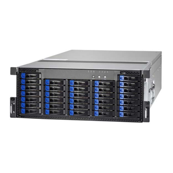
IT demand but also offers a smooth path for future application usage. ® TYAN also offers the FT68-B7910 in a version that can support up to sixty-four 2.5" slim type hot-swap hard drives. The FT68-B7910 uses TYAN’s latest chassis featuring a robust structure and a solid mechanical enclosure. -
Page 18: Features
Features TYAN FT68B7910 (B7910F68W32HR-2T [BTO]) Form Factor 4U Rackmount Gross Weight 28 kg Chassis Model FT68 System Dimension (D x W x 27.52" x 17.44" x 6.9" (688 x 436 x 175mm) Motherboard S7910WGM2NR-2T Board Dimension Prop. 21.47" x 16.65" (545.5 x 423mm) - Page 19 M7910-R56-3F1L, PCI-E x16 & x8 4U riser card Pre-install TYAN (right) / M7910-L56-3F1L, PCI-E x16 & x8 4U riser Riser Card card (left) Port Q'ty (2) 10GbE ports + (1) dedicated for IPMI Controller Intel X540-AT2 Marvell 88E1111 Controller LSI SAS2308 Speed 6.0 Gb/s...
- Page 20 (1) sliding rail kit for FT68 Package Manual (1) Quick Ref. Guide Contains Installation CD (1) TYAN installation CD (2) CCBL-0310, US type power cord / (2) Cable Power Cord CCBL-0300, EU type power cord TYAN FT68B7910 (B7910F68W64HR-2T [BTO]) Form Factor...
- Page 21 (6) FH/FLPCI-E Gen.3 x16 slots / (2) FH/FLPCI-E PCI-E Gen.3 x8 slots Expansion Slots M7910-R56-3F1L, PCI-E x16 & x8 4U riser card Pre-install TYAN (right) / M7910-L56-3F1L, PCI-E x16 & x8 4U riser Riser Card card (left) Port Q'ty (2) 10GbE ports + (1) dedicated for IPMI...
- Page 22 (4) Socket R CPU heatsinks Rail kit (1) sliding rail kit for FT68 Package Manual (1) Quick Ref. Guide Contains Installation CD (1) TYAN installation CD (2) CCBL-0310, US type power cord / (2) Cable Power Cord CCBL-0300, EU type power cord http://www.tyan.com...
-
Page 23: Standard Parts List
Standard Parts List This section describes FT68-B7910 package contents and accessories. Open the box carefully and ensure that all components are present and undamaged. The product should arrive packaged as illustrated below. 1.4.1 Box Contents Component Description (1) 4U FT68 Chassis TYAN®... -
Page 24: Accessories
If any items are missing or appear damaged, contact your retailer or browse to ® TYAN ’s website for service: http://www.tyan.com ® The web site also provides information of other TYAN products, as well as FAQs, compatibility lists, BIOS settings, etc. Screw Pack x 2 Heatsink x 4 AC Power Cord 125V... -
Page 25: About The Product
HDD Bays Front Panel Board HDD LEDs Color State Description Solid On Drive present, no activity Activity LED Green Blinking Drive present, with activity Solid On HDD Failed Blinking Status LED Identify (Locate the HDD) @1Hz Blinking RAID Rebuild @4Hz http://www.tyan.com... - Page 26 HDD Sequence For B7910F68W32HR-2T For B7910F68W64HR-2T NOTE: A single HDD tray can fit in two 2.5” slim SAS/SATA HDDs. http://www.tyan.com...
- Page 27 Front Panel Board LAN2 LED LAN1 LED BMC LED Power LED HDD Activity LED Warning LED ID LED POWER ON/OFF Button ID Button Reset Button http://www.tyan.com...
-
Page 28: System Rear View
1.5.2 System Rear View Expansion Slots (1+1) Redundant Power (upper: PSU0, lower: PSU1) USB Ports ID LED BMC LED VGA Port COM Port LAN2 LAN1 http://www.tyan.com... -
Page 29: Led Definitions
100 Mbps Active Green Blinking Green Solid On Link 1000 Mbps Green Solid On Yellow Solid On (1Gbps) Active Green Blinking Yellow Solid On Link Yellow Solid On Yellow Solid On 10 Gbps Active Green Blinking Yellow Solid On http://www.tyan.com... -
Page 30: System Top View
1.5.4 System Top View Without Air Duct and Riser Card Brackets Right Riser Card Bracket Left Riser Card Bracket Air Duct System Fans Power Distribution Board Power Supply CPU Sockets Memory Slots HDD Backplane Board http://www.tyan.com... -
Page 31: Chapter 2: Hardware Setup
Caution! To avoid damaging the motherboard and associated components, do not use torque force greater than 7kgf/cm (6.09 lb/in) on each mounting screw for motherboard installation. Do not apply power to the board if it has been damaged. http://www.tyan.com... -
Page 32: Precautions
Working on a system that is connected to a power supply can be extremely dangerous. Follow the guidelines below to avoid damage to FT68-B7910 or injury to yourself. Ground yourself properly before removing the top cover of the system. -
Page 33: Installing Motherboard Components
CPUs, memory modules, HDD and PCI-E cards. 2.1.1 Removing the Chassis Cover Follow these instructions to remove the FT68-B7910 chassis cover. Loosen the thumb screw on the rear and the screw on both sides of the chassis. Slide the rear and front cover off. - Page 34 To remove the left riser card bracket, push the orange tab to release the latches. Pull the latches apart. Maker sure to fully open the latches before removing the left riser card bracket. http://www.tyan.com...
- Page 35 Remove the left riser card bracket from the chassis. Repeat the same procedures (Step 3~6) to remove the right riser card bracket. Remove the air duct from the chassis. http://www.tyan.com...
-
Page 36: Installing The Cpu And Heatsink
Locate the CPU0 socket. Always start with CPU0 first. Pull the first and second levers slightly away from the socket and then push them to a fully open position. Push the CPU socket cover to a fully open position. http://www.tyan.com... - Page 37 Place the CPU into the socket and make sure that the gold arrow is located in the right direction. Take out the protection cap after installing the CPU. Close the CPU socket cover and press the levers down to secure the CPU. http://www.tyan.com...
- Page 38 Position the heatsink on top of the CPU and secure it with 4 screws. Repeat the procedures mentioned earlier to install other processors and heatsinks. http://www.tyan.com...
-
Page 39: Installing The Memory
Align the memory module with the slot. When inserted properly, the memory slot locking levers lock automatically onto the indentations at the ends of the module. Follow the recommended memory population table to install the other memory modules. http://www.tyan.com... -
Page 40: Installing The Expansion Cards
2.1.4 Installing the Expansion Cards The FT68-B7910 system has riser card brackets. Follow these instructions to install expansion cards onto the bracket. Take out the riser card brackets. Pre-installed riser card: M7910-L56-3F1L Pre-installed riser card: M7910-R56-3F1L Turn the riser card bracket over and use a screw driver to loosen the screws. - Page 41 Turn the riser card bracket over again. Push the latch forward to unlock the PCI dummy brackets. http://www.tyan.com...
- Page 42 Remove the PCI dummy bracket. Install the expansion card onto the riser card bracket carefully. Move the stopper to secure the expansion card. http://www.tyan.com...
- Page 43 Repeat the same procedures for the other riser card bracket. Remember to push the latch back in place to secure the expansion card. The installation of the expansion cards is now complete. http://www.tyan.com...
-
Page 44: Installing Hard Drives
2.1.5 Installing Hard Drives The FT68-B7910 has thirty-two (32) HDD bays and can support up to sixty-four (64) 2.5” SAS/SATA HDDs or SDDs. Follow these instructions to install a SAS/SATA HDD or SSD. Warning!!! Always install the hard disk drive to the chassis after the chassis is secured on the rack. - Page 45 Slide the HDD tray out. Unscrew the HDD tray and place a 2.5" SAS/SATA HDD or SSD into the HDD tray. Secure the HDD using 4 HDD screws. http://www.tyan.com...
- Page 46 Reinsert the HDD tray into the chassis and press the locking lever to secure the tray. http://www.tyan.com...
-
Page 47: Installing The Usb Dom Card
Follow these instructions to install the USB DOM Card. Take out the USB DOM Card. Locate the USB DOM Connector and place the USB DOM Card on top of the connector. Screw the USB DOM card to the motherboard. http://www.tyan.com... -
Page 48: Installing The Sata Dom Card
Installing the SATA DOM Card Follow these instructions to install the SATA DOM Card. Take out the SATA DOM Card and SATA DOM Bracket. Place the SATA DOM Card on the bracket. Screw the SATA DOM card to the bracket. http://www.tyan.com... - Page 49 Locate the SATA DOM Connectors on the motherboard. Screw the SATA DOM Bracket to the motherboard. http://www.tyan.com...
-
Page 50: Installing The Msata Dom Card
Follow these instructions to install the mSATA DOM Card. Take out the mSATA DOM Card. Locate the mSATA DOM Card slots on the motherboard. Insert the mSATA DOM Card onto the slot. Screw the mSATA DOM card to the motherboard. http://www.tyan.com... -
Page 51: Rack Mounting
Follow these instructions to mount the TYAN FT68-B7910 into an industry standard 19” rack. NOTE: Before mounting the TYAN FT68-B7910 in a rack, ensure that all internal components have been installed and that the unit has been fully tested. 2.2.1 Installing the inner Rails to the Chassis Draw out the inner rails from the rail assembly. -
Page 52: Installing The Outer Rails To The Rack
Hook the outer rail to the rack for each side. Make sure that the anchor point aligns to the middle of the rail. Secure the rails to the rack as shown. Repeat Step 2 if you want to install more chassis to the rack. http://www.tyan.com... -
Page 53: Rack Mounting The Server
To install the chassis to the rack Extend the outside rails to its maximal length. Lift the chassis and then insert the inner rails into the outside rails. Push the locking tab forward to slide the chassis into the rack. http://www.tyan.com... - Page 54 Screw the chassis to the rack. The rack mounting of FT68-B7910 is now complete. http://www.tyan.com...
- Page 55 To remove the chassis from the rack Unscrew the chassis. Press the locking tabs on both sides of the chassis to pull the chassis out. Push down the blue locking tab on the outer rail to unhook the chassis. http://www.tyan.com...
- Page 56 Lift the lever slightly away to unhook the outer rail from the rack. Note: To avoid injury, it is strongly recommended that two people lift the TYAN FT68-B7910 into the place while a third person screws it to the rack. http://www.tyan.com...
-
Page 57: Chapter 3: Replacing Pre-Installed Components
This chapter explains how to replace the pre-installed components, including the S7910 Motherboard, M7910F68-FPB Front Panel Board, M7910F68-BP6-32 M7910F68-BP6-64 SATA/SAS HDD Backplane Board, M1615F68-D-PDB Power Distribution Board, M7910-L56-3F1L/M7910-R56-3F1L PCI-E Riser Card Brackets, System Fan and Power Supply Unit etc. 3.0.2 Disassembly Flowchart The following flowchart outlines the disassembly procedures. http://www.tyan.com... -
Page 58: Removing The Cover
Removing the Cover Before replacing any parts you must remove the chassis cover. Follow Section 2.1.1 Removing the Chassis Cover (page 33) to remove the cover of the FT68-B7910. Replacing the System Fan Follow these instructions to replace the system fan. -
Page 59: Removing The Fan Cradle
Removing the Fan Cradle Push the orange tab to release the fan cradle from the chassis. Use two hands to take out the fan cradle. Reinstall the fan cradle back into the chassis following the direction as the arrows show. http://www.tyan.com... -
Page 60: Replacing The Hdd Backplane Board
Removing the Fan Cradle (p. 59) on how to remove the Fan Cradle. Disconnect the LCD Control Cable and unscrew the HDD BP Board. Loosen the screws on both sides of the chassis. Take out the HDD BP Bracket. http://www.tyan.com... - Page 61 Unscrew 14 screws to replace with a new HDD Backplane Board. Reinstall it into the chassis following the steps in reverse. http://www.tyan.com...
-
Page 62: Hdd Bp Board Features
3.3.1 HDD BP Board Features Here shows the M7910F68-BP6-32 SATA/SAS HDD Backplane Board in details. Front view: Rear view: http://www.tyan.com... - Page 63 SAS-HDD12 Connector SAS-HDD13 Connector SAS-HDD14 Connector SAS-HDD15 Connector SAS-HDD16 Connector SAS-HDD17 Connector SAS-HDD18 Connector SAS-HDD19 Connector SAS-HDD20 Connector SAS-HDD21 Connector SAS-HDD22 Connector SAS-HDD23 Connector SAS-HDD24 Connector SAS-HDD25 Connector SAS-HDD26 Connector SAS-HDD27 Connector SAS-HDD28 Connector SAS-HDD29 Connector SAS-HDD30 Connector SAS-HDD31 Connector http://www.tyan.com...
- Page 64 Here shows the M7910F68-BP6-64 SATA/SAS HDD Backplane Board in details. Front view: Rear view: http://www.tyan.com...
- Page 65 SAS-HDD24/25 Connector SAS-HDD26/27 Connector SAS-HDD28/29 Connector SAS-HDD30/31 Connector SAS-HDD32/33 Connector SAS-HDD34/35 Connector SAS-HDD36/37 Connector SAS-HDD38/39 Connector SAS-HDD40/41 Connector SAS-HDD42/43 Connector SAS-HDD44/45 Connector SAS-HDD46/47 Connector SAS-HDD48/49 Connector SAS-HDD50/51 Connector SAS-HDD52/53 Connector SAS-HDD54/55 Connector SAS-HDD56/57 Connector SAS-HDD58/59 Connector SAS-HDD60/61 Connector SAS-HDD62/63 Connector http://www.tyan.com...
-
Page 66: Hdd Bp Board Block Diagram
3.3.2 HDD BP Board Block Diagram Here shows the M7910F68-BP6-32 SATA/SAS HDD Backplane Board Block Diagram. http://www.tyan.com... - Page 67 Here shows the M7910F68-BP6-64 SATA/SAS HDD Backplane Board Block Diagram. http://www.tyan.com...
-
Page 68: Replacing The Front Panel Board
Replacing the Front Panel Board Follow these instructions to replace the M7910F68-FPB Front Panel Board. Pull the HDD trays forwards. Unscrew to release front panel board bracket. http://www.tyan.com... - Page 69 Push forward to slide the front panel bracket out of the chassis. Remove three screws and the LED control cable to take out the front panel board. After replacement, insert the unit into the chassis following the above procedures in reverse. http://www.tyan.com...
-
Page 70: Front Panel Board Features
(3) Switches Power On/Off (with green LED) ID (with blue LED, optional) Reset (optional) (6) LED Indicators Specifications 2 LAN LEDs 1 BMC LED 1 System Fault 1 ID 1 HDD http://www.tyan.com... -
Page 71: Front Panel Board Led Indications
Green HDD Ready Solid On System Warning Warning Amber System Normal Switches Color State Description Free No Operation Power Green Push Trigger Power Event Free No Operation Blue Push Trigger ID LED Free No Operation Reset Push Reset System http://www.tyan.com... -
Page 72: Replacing The Power Distribution Board
Replacing the Power Distribution Board Follow these instructions to replace the M1615P68-D-PDB Power Distribution Board. First take out the power supplies. Press the orange tab to release the power distribution board bracket. Take out the PDB Bracket from the chassis. http://www.tyan.com... - Page 73 Unscrew the power distribution board from the bracket and replace with a new one. Follow the steps described earlier in reverse order to reinstall the power distribution board into the chassis. http://www.tyan.com...
-
Page 74: Power Distribution Board Features
3.5.1 Power Distribution Board Features Form Factor 164.0mm x 164.7mm, 8-layer PCB (2) 8-pin Power Connectors (PW1, PW2) Specifications (1) 10-pin Function Signal Connector (J8) (6) 4-pin Power Connector (J4/J5/J6/J7/J9/J10) FCC Class B (DoC) Regulations European Community CE (DoC) http://www.tyan.com... -
Page 75: Pin Definitions
J7: 4-Pin Power Connector Definition Definition SLOT_R_P12V P2_P12V J9: 4-Pin Power Connector Definition Definition ATX_VCC5_SB FAN_P12V BP2_P12V J10: 4-Pin Power Connector Definition Definition BP3_P12V BP0_P12V BP1_P12V J8: 10-pin Function Signal Connector Definition Definition PDB_CLK PDB_ALERT PDB_DAT RISER_L_PT PSU_PWROK RISER_R_PT PSON_SYS_L BP_PT 5VSB_OFF http://www.tyan.com... - Page 76 PW1: 8-Pin Power Connector Definition Definition PS_12V11 PS_12V11 PS_12V12 PS_12V12 PW2: 8-Pin Power Connector Definition Definition PS_12V13 PS_12V13 PS_12V14 PS_12V14 http://www.tyan.com...
-
Page 77: Replacing The Power Supply
Please unplug the power cord before you follow these instructions to replace the power supply units. Press and hold the latch to pull the power supply out. After replacing a new power supply, press and hold the latch to push the power supply back into the chassis. http://www.tyan.com... - Page 78 NOTE http://www.tyan.com...
-
Page 79: Chapter 4: Motherboard Information
Caution! To avoid damaging the motherboard and associated components, do not use torque force greater than 7kgf/cm (6.09 lb/in) on each mounting screw for motherboard installation. Do not apply power to the board if it has been damaged. http://www.tyan.com... -
Page 80: Board Image
Board Image S7910 This picture is representative of the latest board revision available at the time of publishing. The board you receive may not look exactly like the above picture. http://www.tyan.com... -
Page 81: Block Diagram
Block Diagram S7910 Block Diagram http://www.tyan.com... -
Page 82: Mainboard Mechanical Drawing
Mainboard Mechanical Drawing http://www.tyan.com... -
Page 83: Board Parts, Jumpers And Connectors
This diagram is representative of the latest board revision available at the time of publishing. The board you receive may not look exactly like the above diagram. For the latest board revision, please visit our web site at http://www.tyan.com. http://www.tyan.com... - Page 84 J115 / J116 / J117 / J118 / J123 RISER R Connector J121 / J122 USB DOM1 Connector / USB DOM0 Connector LED29 (ID_LED) ID LED Jumper Legend OPEN - Jumper OFF Without jumper cover CLOSED - Jumper ON With jumper cover http://www.tyan.com...
- Page 85 http://www.tyan.com...
- Page 86 4. Put jumper cap back to Pin_1 and Pin_2 (Default setting). 5. Reconnect power connectors to the motherboard and power on system. Clear CMOS / Data J32: BIOS Recovery Setting Jumper Pin 1-2 Closed: Normal Mode (Default) Pin 2-3 Closed: Recovery Mode J35: COM2 Header Signal Signal SOUT http://www.tyan.com...
- Page 87 http://www.tyan.com...
- Page 88 (Default) NOTE: If the designated BIOS ROM does not function properly, the system will automatically switch to the other ROM after several restarts. Pin 2-3 Closed: BIOS ROM1 Open: BIOS ROM2 J69: Flash Security Override Header Signal V3P3_AUX AUD_AZA_SDO http://www.tyan.com...
- Page 89 LED29 J121 J122 J100 http://www.tyan.com...
- Page 90 LED29 (ID_LED): ID LED Signal P3V3_AUX ID_SW_L NOTE: The ID LED can be activated remotely using IPMI. http://www.tyan.com Please visit the TYAN Web Site at to download the latest IPMI Configuration Guide for more details. J121/J122: USB DOM Connector Signal Signal USBD-...
- Page 91 http://www.tyan.com...
- Page 92 J47/J48: SATA DOM Connector Signal Signal SATA TX+ SATA TX- SATA RX- SATA RX+ +12V +12V +12V J68: IPMB Connector Signal Signal BMC_SMB_DATA BMC_SMB_CLK http://www.tyan.com...
-
Page 93: Thermal Interface Material
CPU lid (applying too much will actually reduce the cooling). NOTE: Always check with the manufacturer of the heat sink & processor to ensure that the thermal interface material is compatible with the processor and meets the manufacturer’s warranty requirements. http://www.tyan.com... -
Page 94: Tips On Installing Motherboard In Chassis
Be especially careful to look for extra stand-offs. If there are any stand-offs present that are not aligned with a mounting hole on the motherboard, it will likely short components on the back of the motherboard when installed. This will cause malfunction and/or damage to your motherboard. http://www.tyan.com... - Page 95 Some chassis include plastic studs instead of metal. Although the plastic studs are usable, MiTAC recommends using metal studs with screws that will fasten the motherboard more securely in place. Below is a chart detailing what the most common motherboard studs look like and how they should be installed. http://www.tyan.com...
-
Page 96: Installing The Memory
Installing the Memory Before installing memory, ensure that the memory you have is compatible with the motherboard and processor. Check the TYAN Web site at http://www.tyan.com details of the type of memory recommended for your motherboard. The following pictures show common types of DDR3 memory modules. - Page 97 4. Dual-rank DIMMs are recommended over single-rank DIMMs. 5. Un-buffered DIMM can offer slightly better performance than registerd DIMM if populating only a single DIMM per channel. 6. Always install with CPU0 Socket and DIMM_0 Slot first, following the alphabetical order. http://www.tyan.com...
- Page 98 CPU0_DIMM_C1 √ √ √ CPU0_DIMM_D0 √ CPU0_DIMM_D1 √ √ √ √ √ √ √ √ CPU1_DIMM_A0 √ CPU1_DIMM_A1 √ √ √ √ √ √ CPU1_DIMM_B0 √ CPU1_DIMM_B1 √ √ √ √ CPU1_DIMM_C0 √ CPU1_DIMM_C1 √ √ CPU1_DIMM_D0 √ CPU1_DIMM_D1 http://www.tyan.com...
- Page 99 √ √ √ √ √ √ √ MM_C0 CPU1_DI √ MM_C1 CPU1_DI √ √ √ √ √ √ MM_D0 CPU1_DI √ MM_D1 CPU2_DI √ √ √ √ √ √ √ √ √ √ √ √ √ √ √ MM_A0 http://www.tyan.com...
- Page 100 √ √ √ √ √ MM_A0 CPU3_DI √ MM_A1 CPU3_DI √ √ √ MM_B0 CPU3_DI √ MM_B1 CPU3_DI √ √ √ √ √ √ √ √ √ √ MM_C0 CPU3_DI √ MM_C1 CPU3_DI √ √ MM_C0 CPU3_DI √ MM_C1 http://www.tyan.com...
- Page 101 1DPC => One dimm per channel NOTE 4: 2DPC => Two dimm per channel Supported DRAM Densities are 1Gb, 2Gb and 4Gb. Only 2Gb and 4Gb are validated by Intel. Command Address Timing is 1N for 1DPC and 2N for 2DPC. http://www.tyan.com...
- Page 102 Supported and validated DRAM Densities are 2Gb and 4Gb. Command Address Timing is 1N. The speeds are estimated targets and will be verified through simulation. For 3SPC/3DPC -Rank Multiplication (RM) >= 2. DDP -Dual Die Package DRAM stacking. P –Planer monolithic DRAM Die. http://www.tyan.com...
- Page 103 Command Address Timing is 1N. QR RDIMM are supported but not validated by Intel/PMO in a homogenous environment. The coverage will have limited system level testing, no signal integrity testing, and no interoperability testing. The passing QR RDIMMs will be web posted. http://www.tyan.com...
-
Page 104: Finishing Up
In the rare circumstance that you have experienced difficulty, you can find help by asking your vendor for assistance. If they are not available for assistance, please find setup information and documentation online at our website or by calling your vendor’s support line. http://www.tyan.com... -
Page 105: Chapter 5: Bios Setup
The table below shows how to navigate in the setup program using the keyboard. Function Left/Right Arrow Keys Change from one menu to the next Up/Down Arrow Keys Move between selections Enter Open highlighted section PgUp/PgDn Keys Change pages Change options Exit http://www.tyan.com... -
Page 106: Getting Help
The following pages provide the details of BIOS menu. Please be noticed that the BIOS menu are continually changing due to the BIOS updating. The BIOS menu provided are the most updated ones when this manual is written. Please visit TYAN’s website at http://www.tyan.com for the information of BIOS updating. -
Page 107: Main Menu
It displays BIOS related information. Memory Information This displays the total memory size. System Date Adjust the system date. MM (Months): DD (Days): YYYY (Years) System Time Adjust the system clock. HH (24 hours format): MM (Minutes): SS (Seconds) Access Level Read only. http://www.tyan.com... -
Page 108: Advanced Menu
This section facilitates configuring advanced BIOS options for your system. ACPI Settings System ACPI Parameters. CPU Configuration CPU Configuration Parameters. Runtime Error Logging Runtime Error Logging Support Setup Options Onboard Device Configuration Onboard Device Configuration. SATA Configuration SATA Devices Configuration. Info Report Configuration Info Report Configuration. http://www.tyan.com... - Page 109 USB Configuration USB Configuration Parameters. Hardware Health Configuration Hardware health Configuration Parameters. Super IO Configuration System Super IO Chip Parameters. Serial Port Console Redirection Serial Port Console Redirection. http://www.tyan.com...
-
Page 110: Acpi Settings
Enable or disable System ability to Hibernate (OS/S4 Sleep State). This option may not be effective with some OS. Disabled / Enabled ACPI Sleep State Select the highest ACPI sleep state the system will enter when the SUSPEND button is pressed. Suspend Disabled / S1 only (CPU Stop Clock) http://www.tyan.com... -
Page 111: Cpu Configuration
When disabled only one thread per enabled core is enabled. Enabled / Disabled Active Processor Cores Number of cores to enable in each processor package. All / 1 / 2 / 4 / 6 Limit CPUID Maximum Disabled for Windows XP. Disabled / Enabled http://www.tyan.com... - Page 112 Intel Virtualization Technology When enabled, a VMM can utilize the additional hardware capabilities provided by Vanderpool Technology. NOTE: Once the lock bit is set, the contents of this register can not be modified until S5 reset occurs. Enabled / Disabled http://www.tyan.com...
- Page 113 5.3.2.1 Socket 0 CPU Information Read only. http://www.tyan.com...
- Page 114 EIST Enable/Disable Intel StepSpeed. Disabled / Enabled Turbo Mode Enable/Disable Turbo Mode. Enabled / Disabled P-STATE Coordination Change P-State coordination type. HW_ALL / SW_ALL / SW_ANY CPU C3 Report Enable/Disable CPU Core C3 report to OS. Disabled / Enabled http://www.tyan.com...
- Page 115 Long duration power limit in Watts. Factory Long Duration Maintained Read only. Long Duration Maintained Time window which the long duration power is maintained. Recommended short duration power limit Read only. Short duration power limit Short duration power limit in Watts. http://www.tyan.com...
-
Page 116: Runtime Error Logging
PCI Error Logging Support Enable/Disable PCI Error Logging. Disabled / Enabled Poison Support Enable/Disable Poision Support. When poisoning is enabled, CPU does not signal the uncorrectable error via MCERR but may signal CMCI if CMCI is enabled. Disabled / Enabled http://www.tyan.com... -
Page 117: Onboard Device Configuration
The BIOS will automatically read the onboard LAN controller. Onboard LAN0 Enable PXE/ISCSI or disable onboard Gigabit LAN0 Option ROM. Disabled / PXE / ISCSI NOTE: The ISCSI function is only supported in LAN0 Onboard LAN1 Enable or disable onboard Gigabit LAN1 Option ROM. Disabled / PXE http://www.tyan.com... - Page 118 PCIe P1_1A OPTROM Enable or disable OPTROM for PCIe slot. Enabled / Disabled PCIe P0_3A OPTROM Enable or disable OPTROM for PCIe slot. Enabled / Disabled PCIe P0_2C OPTROM Enable or disable OPTROM for PCIe slot. Enabled / Disabled http://www.tyan.com...
-
Page 119: Sata Configuration
SATA Port 0 / 1 / 2 / 3 Read only. SATA Mode Select SATA Mode. IDE Mode / AHCI Mode / RAID Mode / Disabled Port 0/1/2/3/ Hot Plug Enable/Disable SATA Ports Hot Plug Support. Disabled / Enabled http://www.tyan.com... -
Page 120: Info Report Configuration
5.3.6 Info Report Configuration Post Report Post Report Support enabled/disabled. Disabled / Enabled Info Error Message Info Error Message Support enabled/disabled. Disabled / Enabled Summary Screen Summary Screen Support enabled/disabled. Disabled / Enabled http://www.tyan.com... -
Page 121: Usb Configuration
USB Configuration USB Devices Read only. Legacy USB Support Enable USB legacy support. AUTO option disables legacy support if no USB devices are connected. DISABLE option will keep USB devices available only for EFI applications. Enabled / Disabled / Auto http://www.tyan.com... -
Page 122: Hardware Health Configuration
Hardware Health Configuration BMC Alert Beep BMC Alert Beep On/Off. On / Off 5.3.8.1 Sensor Data Register Monitoring When you enter the Sensor Data Register Monitoring submenu, you will see the following dialog window pop out. Please wait 8~10 seconds. http://www.tyan.com... - Page 123 http://www.tyan.com...
- Page 124 NOTE: SDR can not be modified. Read only. http://www.tyan.com...
-
Page 125: Super Io Configuration
5.3.9 Super IO Configuration Super IO Chip Read only. http://www.tyan.com... - Page 126 / IO=3F8h, IRQ=3, 4, 5, 6, 7, 10, 11, 12; / IO=2F8h; IRQ=3, 4, 5, 6, 7, 10, 11, 12; / IO=3E8h, IRQ=3, 4, 5, 6, 7, 10, 11, 12; / IO=2E8h, IRQ=3, 4, 5, 6, 7, 10, 11, 12; Change Settings SUART clock source. 24MHZ/13 / 24MHz http://www.tyan.com...
-
Page 127: 5.3.10 Serial Port Console Redirection
Serial Port for Out-Of-Band Management/Windows Emergency Services (EMS) Console Redirection Console Redirection enable or disable. Disabled / Enabled Console Redirection Settings The settings specify how the host computer (which the user is using) will exchange data. Both computers should have the same or compatible settings. http://www.tyan.com... - Page 128 0 if the num of 1’s in the data bits is even. Odd: parity bit is 0 if the num of 1’s in the data bits is odd. Mark: parity bit is always 1. Space: parity bit is always 0. Mark and Space parity do not allow for error detection. None / Even / Odd / Mark / Space http://www.tyan.com...
- Page 129 Redirection after BIOS POST The settings specify if BootLoader is selected than Legacy console redirection is disabled before booting to Legacy OS. Default value is Always Enable which means Legacy console redirection is enabled for Legacy OS. Always Enable / BootLoader http://www.tyan.com...
- Page 130 115200 / 9600 / 19200 / 57600 Flow Control Flow Control can prevent data loss from buffer overflow. When sending data, if the receiving buffers are full, a ‘stop’ signal can be sent to stop the data flow. Once the http://www.tyan.com...
- Page 131 ‘start’ signal can be sent to restart the flow. Hardware flow control uses two wires to send start/stop signal. None / Hardware RTS/CTS / Software Xon/Xoff Data Bits / Parity / Stop Bits Read only. http://www.tyan.com...
-
Page 132: Chipset Menu
Chipset Menu North Bridge North Bridge Parameters. South Bridge South Bridge Parameters. WatchDog Timer Configuration WatchDog Timer Configuration. http://www.tyan.com... -
Page 133: North Bridge
Enabling this Force SPD option violates design specifications and may cause system instability and or damage to system memory. Enable at your own risk. Auto / Force DDR3 800 / Force DDR3 1066 / Force DDR3 1333 / Force DDR3 1600 / Force SPD http://www.tyan.com... - Page 134 With Manual option user can force the PCI resource allocation across multiple IOHs based on the ratios selected. Auto / Manual MMIOH Size Select number of 1GB contiguous regions to be assigned MMIOH space per CPU. 1G / 2G / 4G / 8G / 16G / 32G / 64G / 128G http://www.tyan.com...
- Page 135 IOH 3 PCIe Port Bifurcation Control PORT 2A Link Speed ® Enable/Disable Intel I/O Acceleration Technology (I/OAT). Gen1 / Gen2 / Gen3 PORT 3A Link Speed Decides priority between onboard and 1st offboard video device found. Gen1 / Gen2 / Gen3 http://www.tyan.com...
- Page 136 Disabled / Enabled ® NOTE: The following items will appear when Intel VT-d is set to [Enabled]. Coherency Support Enable/Disable VT-d Engine Coherency Support. Disabled / Enabled ATS Support Enable/Disable VT-d Engine Address Translation Services support. Enabled / Disabled http://www.tyan.com...
- Page 137 QPI Configuration Submenu QPI Link Speed Mode Select the QPI link speed as either the Fast Mode or the Slow Mode. Fast / Slow QPI Link Frequency Select Select the QPI Link Frequency. Auto / 6.4GT/s / 7.2GT/s / 8.0GT/s http://www.tyan.com...
- Page 138 5.4.1.3 DIMM Information Submenu Read only. http://www.tyan.com...
-
Page 139: South Bridge
Select a minimum assertion width of the SLP_S4# signal. 4-5 Seconds / 1-2 Seconds / 2-3 Seconds / 3-4 Seconds Chassis Intrusion Detection Enabled: When a chassis open event is detected, the BIOS will display the event. Disabled / Enabled http://www.tyan.com... -
Page 140: Watchdog Timer Configuration
Disabled / POST / OS / PowerOn NOTE: Watch Dog Timer will not appear when Watch Dog Mode is set to [Disabled]. Watch Dog Timer Watch Dog Timer Help. 2 MINS / 4 MINS / 6 MINS / 8 MINS / 10 MINS http://www.tyan.com... -
Page 141: Boot
Bootup NumLock State Select the keyboard NumLock state. Off / On Quiet Boot Enable or disable Quiet Boot option. Disabled / Enabled CSM Module Version Read only. Option ROM Messages Select display mode for Option ROM. Force BIOS / Keep Current http://www.tyan.com... - Page 142 HDD is GPT then enable UEFI options, otherwise disable. Enabled: Enable all UEFI boot options. Disabled: Disable all UEFI boot options. Disabled / Enabled / Auto Boot Option #1 Select the first boot device. Device Name / Disabled http://www.tyan.com...
-
Page 143: Security
Confirm New Password window will pop out to ask for confirmation. User Password Set user password in the Create New Password window. After you key in the password, the Confirm New Password window will pop out to ask for confirmation. http://www.tyan.com... -
Page 144: Server Management
Server Management Press <Enter> to change the SEL event log configuration. Enable/Disable interfaces to communicate with BMC. http://www.tyan.com... -
Page 145: System Event Log
Choose options for reactions to a full SEL. Do Nothing / Erase Immediately Log EFI Status Codes Disable the logging of EFI Status Codes or log only error code or only progress code or both. Both / Disabled / Error Code / Progress Code http://www.tyan.com... -
Page 146: Bmc Network Configuration
BMC). Unspecified option will not modify any BMC network parameters during BIOS phase. Unspecified / Static / Dynamic-Obtained by BMC Station IP Address / Subnet Mask / Station MAC Address / Router IP Address / Router MAC Address Read only. http://www.tyan.com... -
Page 147: Event Logs
Event Logs Read only. http://www.tyan.com... -
Page 148: Save & Exit
Discard Changes and Reset Reset system setup without saving any changes. Save Options Read only. Save Changes Save changes done so far to any of the setup options. Discard Changes Discard changes done so far to any of the setup options. http://www.tyan.com... - Page 149 Restore Defaults Restore/Load Default values for all the setup options. Save as User Defaults Save the changes done so far as User Defaults. Restore User Defaults Restore the User Defaults to all the setup options. Boot Override Read only. http://www.tyan.com...
- Page 150 NOTE http://www.tyan.com...
-
Page 151: Chapter 6: Diagnostics
BIOS flash failure, you must contact your dealer for a replacement BIOS. There are no exceptions. TYAN does not have a policy for replacing BIOS chips directly with end users. In no event will TYAN be held responsible for damages done by the end user. -
Page 152: Amibios Post Code (Aptio)
South Bridge initialization before microcode loading 0x05 OEM initialization before microcode loading 0x06 Microcode loading 0x07 AP initialization after microcode loading 0x08 North Bridge initialization after microcode loading 0x09 South Bridge initialization after microcode loading 0x0A OEM initialization after microcode loading 0x0B Cache initialization http://www.tyan.com... - Page 153 CPU post-memory initialization is started. 0x33 CPU post-memory initialization. Cache initialization 0x34 CPU post-memory initialization. Application Processor(s) (AP) initialization 0x35 CPU post-memory initialization. Boot Strap Processor (BSP) selection 0x36 CPU post-memory initialization. System Management Mode(SMM) initialization 0x37 Post-Memory North Bridge initialization is started. http://www.tyan.com...
- Page 154 Reserved for future AMI progress codes S3 Resume Error Codes 0xE8 S3 Resume failed 0xE9 S3 Resume PPI not found 0xEA S3 Resume Boot Script error 0xEB S3 OS wake error 0xEC – 0xEF Reserved for future AMI error codes http://www.tyan.com...
- Page 155 CPU DXE initialization (CPU module specific) 0x67 CPU DXE initialization (CPU module specific) 0x68 PCI host bridge initialization 0x69 North Bridge DXE initialization is started. 0x6A North Bridge DXE SMM initialization is started. 0x6B North Bridge DXE initialization (North Bridge module specific) http://www.tyan.com...
- Page 156 USB initialization is started. 0x9B USB Reset 0x9C USB Detect 0x9D USB Enable 0x9E -0x9F Reserved for future AMI codes 0xA0 IDE initialization is started 0xA1 IDE Reset 0xA2 IDE Detect 0xA3 IDE Enable 0xA4 SCSI initialization is started. http://www.tyan.com...
- Page 157 No Console Output Devices are found. 0xD7 No Console Input Devices are found. 0xD8 Invalid password 0xD9 Error loading Boot Option (LoadImage returned error) 0xDA Boot Option is failed (StartImage returned error). 0xDB Flash update is failed. 0xDC Reset protocol is not available. http://www.tyan.com...
- Page 158 System is waking up from the S3 sleep state. 0x40 System is waking up from the S4 sleep state. 0xAC System has transitioned into ACPI mode. Interrupt controller is in APIC mode. 0xAA System has transitioned into ACPI mode. Interrupt controller is in APIC mode. http://www.tyan.com...
-
Page 159: Chapter 7: Fan And Temp Sensors
(rpm) Temp Sensor: PCH_Area_Temp and LAN_X540_Temp. They detect the system temperature around. NOTE: The system temperature is measured in a scale defined by Intel, not in Fahrenheit or Celsius. http://www.tyan.com... - Page 160 BIOS Temp Sensor Name Explanation: http://www.tyan.com...
- Page 161 Temperature of CPU0 DIMM B0 Slot CPU0_DIMM_B1 Temperature of CPU0 DIMM B1 Slot CPU0_DIMM_C0 Temperature of CPU0 DIMM C0 Slot CPU0_DIMM_C1 Temperature of CPU0 DIMM C1 Slot CPU0_DIMM_D0 Temperature of CPU0 DIMM D0 Slot CPU0_DIMM_D1 Temperature of CPU0 DIMM D1 Slot http://www.tyan.com...
- Page 162 Temperature of CPU3 DIMM D1 Slot BIOS FAN Sensor Name Explanation SYS_FAN_1 Fan speed of SYS_FAN_1 SYS_FAN_2 Fan speed of SYS_FAN_2 SYS_FAN_3 Fan speed of SYS_FAN_3 SYS_FAN_4 Fan speed of SYS_FAN_4 SYS_FAN_5 Fan speed of SYS_FAN_5 SYS_FAN_6 Fan speed of SYS_FAN_6 http://www.tyan.com...
-
Page 163: Appendix I: Fru Parts Table
Appendix I: FRU Parts Table FT68-B7910 FRU Parts Item Model Number Part Number Picture Description Power Board M1615F68-D-PDB 5411T4570020 M7910-R56-3F1L 5411T4570030 4U PCI-E Riser Card (R) PCBA 4U PCI-E Riser Card (L) M7910-L56-3F1L 5411T4570031 SATA SATA DOM BKT FRU-SO-0020 340T45700009... - Page 164 NOTE http://www.tyan.com...
-
Page 165: Appendix Ii: Technical Support
By offering plenty of options for users, MiTAC serves multiple market segments with the industry’s most competitive services to support them. Please feel free to contact us directly for this service at tech-support@tyan.com Help Resources: 1. See the beep codes section of this manual. - Page 166 (RMA) number. The RMA number should be prominently displayed on the outside of the shipping carton and the package should be mailed prepaid. TYAN will pay to have the board shipped back to you. TYAN® FT68-B7910 Service Engineer’s Manual V1.0 Document No.: D2191-100 http://www.tyan.com...
- Page 167 http://www.tyan.com...
Need help?
Do you have a question about the FT68-B7910 and is the answer not in the manual?
Questions and answers