Table of Contents
Advertisement
Quick Links
Advertisement
Table of Contents

Subscribe to Our Youtube Channel
Related Manuals for TYAN FT48-B8812


Summary of Contents for TYAN FT48-B8812
- Page 1 FT48-B8812 Version 1.2 Rev Service Engineer’s Manual http://www.tyan.com...
- Page 2 http://www.tyan.com...
- Page 3 TYAN products including liability or ® warranties relating to fitness for a particular purpose or merchantability. TYAN retains the right to make changes to produce descriptions and/or specifications ® at any time, without notice. In no event will TYAN...
- Page 4 There will be danger of explosion if battery is incorrectly replaced. Replace only with the same or equivalent type recommended by manufacturer. Dispose of used battery according to manufacturer instructions and in accordance with your local regulations. http://www.tyan.com...
-
Page 5: About This Manual
About this Manual This manual provides you with instructions on supporting your FT48-B8812 barebones system. This manual is intended for experienced users and integrators with hardware knowledge of personal computers. This manual consists of the following parts: Provides an introduction to the FT48-B8812, standard... -
Page 6: Safety Information
SAFETY INFORMATION Before installing and using the FT48-B8812, take note of the following precautions: ·Read all instructions carefully. ·Do not place the unit on an unstable surface, cart or stand. ·Do not block the slots which are provided for system ventilation. -
Page 7: Table Of Contents
Table of Contents Chapter 1: Overview................. 9 About the TYAN FT48-B8812 ..........9 Product Models................. 9 Features.................. 10 Standard Parts List ..............12 1.4.1 Box Contents ............... 12 1.4.2 Accessories ................. 13 Chapter 2: Motherboard Details ............ 15 Board Image ................16 Sensors on the board ............. - Page 8 Security Menu............... 125 Chipset Menu ............... 127 Exit Menu................138 Appendix I: S8812 / FT48 B8812 BIOS Comparisons ....141 Appendix II: Cable Connection Tables ........149 Appendix III: FRU Parts Table ............. 151 Appendix IV: Technical Support ..........152 http://www.tyan.com...
-
Page 9: Chapter 1: Overview
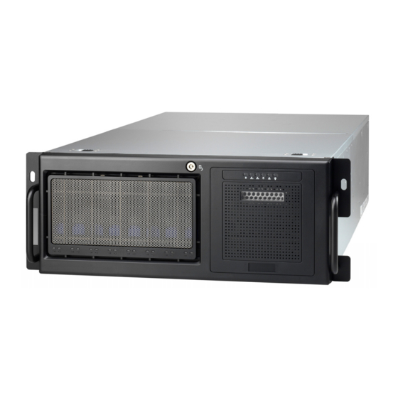
®’ FT48-B8812 uses TYAN s latest rack-mountable 4U chassis featuring a robust structure and a solid mechanical enclosure. All of this provides the FT48-B8812 the power and flexibility to meet the needs of nearly any server application. Product Models Model... -
Page 10: Features
Features TYAN FT48B8812 (B8812F48W8HR) Form Factor 4U Rackmount Chassis Model FT48 Dimension (D x W x H) 27.5" x 16.8" x 6.9" (700 x 427 x 176mm) System Motherboard S8812WGM3NR Board Dimension MEB, 13"x16.2" (330x411mm) Gross Weight 50 kg Buttons... - Page 11 RoHS 6/6 Complaint Barebones (1) FT48 B8812 Barebones Manual (1) FT48 B8812 System Engineer Guide Installation CD (1) TYAN installation CD Heatsink / Cooler (4) G34 CPU heatsinks Package Contains Rail kit (1) CRAL-0070, sliding rail kit for KFT48 (1) CRBK-0021, Rack mounting handle bracket, right /...
-
Page 12: Standard Parts List
Standard Parts List This section describes FT48-B8812 package contents and accessories. Open the box carefully and ensure that all components are present and undamaged. The product should arrive packaged as illustrated below. 1.4.1 Box Contents Component Description 4U Rackmount FT48 Chassis... -
Page 13: Accessories
If any items are missing or appear damaged, contact your retailer or browse to TYAN’s website for service: http://www.tyan.com ® The web site also provides information of other TYAN products, as well as FAQs, compatibility lists, BIOS settings, etc. Rail Kit ®... - Page 14 NOTE http://www.tyan.com...
-
Page 15: Chapter 2: Motherboard Details
(5) Inspect the board for damage. The following pages include details on how to install your motherboard into your chassis, as well as installing the processor, memory, disk drives and cables. NOTE: Do not apply power to the board if it has been damaged. http://www.tyan.com... -
Page 16: Board Image
Board Image This picture is representative of the latest board revision available at the time of publishing. The board you receive may not look exactly like the above picture. http://www.tyan.com... -
Page 17: Sensors On The Board
There are seven different hardware health and IPMI sensors on the S8812 motherboard. Name Function PCI_INLET_AREA Thermometer on board RD5690_CASE_TEMP integrated in the SR5690 chip SAS_CASE_TEMP integrated in the SAS controller chip CPU0_MOS_AREA embedded part CPU1_MOS_AREA embedded part CPU2_MOS_AREA Thermometer on board CPU3_MOS_AREA Thermometer on board http://www.tyan.com... -
Page 18: Block Diagram
Block Diagram S8812 Block Diagram http://www.tyan.com... -
Page 19: Board Parts, Jumpers And Connectors
The board you receive may not look exactly like the above diagram. But for the DIMM number please refer to the above placement for memory installation. For the latest board revision, please visit our web site at http://www.tyan.com. http://www.tyan.com... - Page 20 VGA Disable Jumper JP21/JP22/JP25/JP26 DDR3 VDDIO Voltage Select Jumper JP24 LAN2 LED Connector JP27 ID LED Connector LED1 ID LED USB1/USB2 USB Front Panel Header Jumper Legend OPEN - Jumper OFF Without jumper cover CLOSED - Jumper ON With jumper cover http://www.tyan.com...
- Page 21 http://www.tyan.com...
- Page 22 CPU0 Fan : J55 CPU2 Fan : J10 CPU1 Fan : J9 CPU3 Fan : J14 J18: IPMB Connector Signal Signal IPMB DATA IPMB CLK J66: SAS Fault LED Signal Signal LED_SAS_FAULT-0 LED_SAS_FAULT-1 LED_SAS_FAULT-2 LED_SAS_FAULT-3 LED_SAS_FAULT-4 LED_SAS_FAULT-5 LED_SAS_FAULT-7 LED_SAS_FAULT-6 http://www.tyan.com...
- Page 23 LED1 http://www.tyan.com...
- Page 24 P3V3_AUX ID_SW_L State Color Description Blue System identified System not identified NOTE: IPMI can activate ID LED from remote site. Please visit the TYAN Web Site at http://www.tyan.com to download the latest AST2050 Software Configuration Guide for IPMI settings. http://www.tyan.com...
- Page 25 JP13 JP12 JP10 JP11 http://www.tyan.com...
- Page 26 JP10: BMC Disable Jumper Open: Normal (Default) Closed: BMC Disable JP11/JP12: COM2 Switch Jumper Pin 1-2 Closed: SIO to COM2 (Default) Pin 2-3 Closed: BMC UART2 to COM2 JP13: TPM Disable Jumper Open: Enable TPM (Default) Closed: Disable TPM http://www.tyan.com...
- Page 27 JP19 JP24 JP14 JP16 JP15 USB1 USB2 http://www.tyan.com...
- Page 28 Use this header to trigger the system chassis intrusion alarm. JP19: VGA Disable Jumper Open: Enable VGA (Default) Closed: Disable VGA JP24: LAN3 LED Header Signal LAN3 LED+ LAN3 LED- USB1/USB2: USB Front Panel Connector Signal Signal USB0- USB1- USB0+ USB1+ http://www.tyan.com...
- Page 29 JP25 JP26 JP21 JP22 JP27 http://www.tyan.com...
- Page 30 JP21/JP22/JP25/JP26: DDR3 VDDIO Voltage Select Jumper Open: Support regular 1.5V DDR3 memory (Default) Closed: Support for Low Voltage 1.35V DDR3 memory JP27: ID LED Connector Signal ID LED+ http://www.tyan.com...
-
Page 31: Installing The Processor And Heat Sink
Installing the Processor and Heat sink ® The S8812 supported AMD class of processors are listed on Page 10. Check our website at http://www.tyan.com for latest processor support. NOTE: MiTAC is not liable for damage as a result of operating an unsupported configuration. - Page 32 Lift the socket cover to a fully open position. Take off the CPU protection cap. Place the CPU in the CPU socket. http://www.tyan.com...
- Page 33 Place the heat sink on top of the CPU and secure it to the motherboard with 2 screws. Connect the heat sink Fan cable to the CPU0 FAN connector J55. Repeat the same procedures to install the other heat sinks (CPU1 Fan: J9, CPU2 Fan: J10, CPU3 Fan: J14). http://www.tyan.com...
-
Page 34: Thermal Interface Material
CPU lid (applying too much will actually reduce the cooling). NOTE: Always check with the manufacturer of the heat sink & processor to ensure that the thermal interface material is compatible with the processor and meets the manufacturer’s warranty requirements. http://www.tyan.com... -
Page 35: Tips On Installing Motherboard In Chassis
If there are any studs missing, you will know right away since the motherboard will not be able to be securely installed. http://www.tyan.com... - Page 36 Some chassis include plastic studs instead of metal. Although the plastic studs are usable, MiTAC recommends using metal studs with screws that will fasten the motherboard more securely in place. Below is a chart detailing what the most common motherboard studs look like and how they should be installed. http://www.tyan.com...
-
Page 37: Lights On The Motherboard
State). The blue LED will light because the S5 power has been supplied in S5 Mode. It will blink slowly when the MB works normally in S5 Mode. If it does not blink, it shows that the MB has died in S5 Mode. Green LED (Still): Initializing BMC/Being updated BMC firmware Green LED (Blink): Monitoring hardware health http://www.tyan.com... -
Page 38: Installing The Memory
Installing the Memory Before installing memory, ensure that the memory you have is compatible with the motherboard and processor. Check the TYAN Web site at http://www.tyan.com for details of the type of memory recommended for your motherboard. The following diagram shows common types of DDR3 memory modules. - Page 39 √ √ P3_DIMM(29)B0 √ P3_DIMM(30)B1 √ √ P3_DIMM(31)A0 √ P3_DIMM(32)A1 √ √ NOTE: 1. √ indicates a populated DIMM slot. 2. Pair DIMM module configuration for Max performance. 3. We do not suggest or support any other memory configurations. http://www.tyan.com...
- Page 40 √ √ √ P2_DIMM(17)D0 √ P2_DIMM(18)D1 √ √ P2_DIMM(19)C0 √ P2_DIMM(20)C1 √ √ P2_DIMM(21)B0 √ P2_DIMM(22)B1 √ √ P2_DIMM(23)A0 √ P2_DIMM(24)A1 √ √ P3_DIMM(25)D0 √ √ P3_DIMM(26)D1 √ √ √ √ P3_DIMM(27)C0 √ √ P3_DIMM(28)C1 √ √ √ √ http://www.tyan.com...
- Page 41 Maximum of 8GB per channel SR and DR UDDR3 module support only SR and DR 1.35v Memory MAX speed of 1066MHz in a dual channel configuration SR and DR 1.5v Memory MAX speed of 1333MHz in a dual channel configuration http://www.tyan.com...
- Page 42 SR and DR 1.5v Memory MAX speed of 1333MHz in a dual channel configuration QR Memory has a MAX amount of 32GB per channel QR 1.35v Memory MAX speed of 800MHz in a dual channel configuration QR 1.5v Memory MAX speed of 1066MHz in a dual channel configuration http://www.tyan.com...
- Page 43 http://www.tyan.com...
-
Page 44: Memory Installation Procedure
Hold the DIMM by both of its ends. Insert the module vertically into the socket. Apply force to both ends of the DIMM simultaneously until the retaining clip pop up into place. And the DIMM cannot be pushed in any further to ensure proper sitting of the DIMM。 http://www.tyan.com... -
Page 45: Attaching Drive Cables
Master/Slave jumpers on SATA drives. If you are in need of SATA/SAS cables or power adapters please contact your place of purchase. The following pictures illustrate how to connect an SATA drive. 1. SATA drive cable connection 2. SATA drive power connection 3. SATA cable motherboard connector 4. SATA drive power adapter http://www.tyan.com... -
Page 46: Installing Add-In Cards
Doing so allows air to circulate within the chassis more easily, thus improving cooling for all installed devices. NOTE: You must always unplug the power connector to the motherboard before performing system hardware changes to avoid damaging the board or expansion device. http://www.tyan.com... -
Page 47: Connecting External Devices
LED states. 10/100/1000 Mbps LAN Link/Activity LED Scheme Left LED Right LED Link Green 10 Mbps Active Blinking Green Link Green Green 100 Mbps Active Blinking Green Green Link Green Yellow 1000 Mbps Active Blinking Green Yellow No Link http://www.tyan.com... -
Page 48: Installing The Power Supply
AMD CPU SE models, both 8-pin power connectors will be required. Connect the EPS/12V 24-pin power connector. Connect power cable to power supply and power outlet. NOTE: You must unplug the power supply before plugging the power cables to motherboard connectors. http://www.tyan.com... -
Page 49: Finishing Up
In the rare circumstance that you have experienced difficulty, you can find help by asking your vendor for assistance. If they are not available for assistance, please find setup information and documentation online at our website or by calling your vendor’s support line. http://www.tyan.com... - Page 50 NOTE http://www.tyan.com...
-
Page 51: Chapter 3: About The Barebones Chassis Features
System Front View The front bezel LED control panel Hot-swap HDD Bays 3 * 5.25 inch device bays ID LED LAN2 LED NMI Button LAN1 LED USB Ports HDD LED Reset Button Warning LED Power LED Power Button ID Button http://www.tyan.com... -
Page 52: System Rear View
Users from remote site could also activate ID LED by interfacing with the IPMI. For further details on the IPMI software, please visit http://www.tyan.com for the latest AST2050 user guide. http://www.tyan.com... - Page 53 (Blinking 1 Hz) Rear I/O The three onboard Ethernet ports have green and yellow LEDs to indicate LAN status. The rear I/O LED Please refer to Chapter 2.10 Connecting External Devices Onboard LAN LED Color Definition on page 45. http://www.tyan.com...
-
Page 54: Internal View
(8) HDD trays with (2) M1237F48 SAS backplane ① (Pre-installed) ② M1018 Front Panel Board and (3) 5.25 inch media bays System Fan Module ③ (6) 12038 hot-swap fan as pre-installed ④ System Main Board ⑤ (4) Expansion slots http://www.tyan.com... -
Page 55: Chapter 4: Setting Up
A grounding strap or an anti-static pad Most of the electrical and mechanical connections can be disconnected with your hands. It is recommended that you do not use pliers to remove connectors as it may damage the soft metal or plastic parts of the connectors. http://www.tyan.com... -
Page 56: Precautions
Working on a system that is connected to a power supply can be extremely dangerous. Follow the guidelines below to avoid damage to FT48-B8812 or injury to yourself. Ground yourself properly before removing the top cover of the ... -
Page 57: Installing Motherboard Components
CPUs, memory modules and add on cards. 4.1.1 Removing the Chassis Cover Follow these instructions to remove FT48-B8812 chassis cover. Press the button on the front top cover and slide the cover off. Unscrew the thumb screw securing the rear cover then slide the rear top cover off. -
Page 58: Installing The Pci-E Cards
4.1.2 Installing the PCI-E Cards FT48-B8812 has four PCIe expansion slots. Slot 1 and Slot 2 have x8 PCIe signals. Slot 3 and Slot 4 share a single x16 PCIe signal. If cards are installed on both Slot 3 and Slot 4, then both slots can only expect a maximum of x8 PCIe signal strength. - Page 59 Connect the cables between the expansion card and the power distribution board. The (CCBL-1100) power cable was designed to support up to 2x GPU cards (each w/8-pin power connector per GPU card). http://www.tyan.com...
-
Page 60: Installing Hard Drives
Installing Hard Drives The FT48-B8812 supports up to eight 3.5” hard drives. Follow these instructions to install a hard drive. Press the locking lever latch and pull the locking lever open. Slide the HDD tray out. http://www.tyan.com... - Page 61 Place a 3.5" hard drive into the HDD tray. Turn over the HDD unit and secure the HDD using 4 HDD screws. Reinsert the HDD tray into the chassis and press the locking lever to secure the tray. http://www.tyan.com...
-
Page 62: Installing Dvd Drive
SATA Cable P/N: 422T38700001 DVD PWR cable P/N: 422790900011 Install the DVD Rail-L and Rail-R to the DVD device and secure with the packaged screws. Open the chassis front bezel, and determine the location to insert the DVD device. http://www.tyan.com... - Page 63 Remove the DVD cover BKT. http://www.tyan.com...
- Page 64 Install the DVD device into location 1. DVD rail-R needs to be locked with the chassis hook. http://www.tyan.com...
- Page 65 Remove the J36 connector cable from the HDD BP-1. Insert the SATA cable on the motherboard J50 and route the cable along the side of the chassis. http://www.tyan.com...
- Page 66 Connect the SATA cable to the DVD device. 10. Connect the DVD power Y cable to the HDD PWR cable. 11. Insert DVD power cable Y to the HDD BP-1 connector J36. http://www.tyan.com...
- Page 67 12. Connect the DVD PWR cable to the DVD device. 13. The DVD device has been successfully installed. http://www.tyan.com...
-
Page 68: Rack Mounting
A: Bracket for M6 screw--10 pcs B: M 6--10 pcs C: M 4-L5--16 pcs Installing the Inner Rails to the Unit Step1: Screw the mounting ears to each side of the FT48-B8812 as shown using three M4-L5 screws (C) from the supplied screws kit. http://www.tyan.com... - Page 69 Step2: Secure the outer rails to the Server rack using 4 M6 screws (B) for each side. Secure the mounting brackets from the outside, not the inside of the server rack. http://www.tyan.com...
-
Page 70: Rack Mounting The Server
Rack Mounting the Server Step1: Draw out the middle rail to the latch position. Step2: Lift the unit and then insert the inner slide rails into the middle rails. Step3: Press the latch key and push the whole system in. http://www.tyan.com... -
Page 71: Opening The Chassis Front Bezel
(A) and M6 screws (B). Opening the Chassis Front Bezel Insert the front bezel key (packed in a bag in the accessory box) and rotate the key 90 degrees counterclockwise to unlock the front bezel. Open the front bezel. http://www.tyan.com... - Page 72 NOTE http://www.tyan.com...
-
Page 73: Chapter 5: Replacing Pre-Installed Components
B8812 server chassis, including the Motherboard, four small boards (M1018 Front Panel Board, M1237-F48 HDD Backplane, M1801-F77 Fan Board, M7025-PDB Power Distribution Board) System fan, ODD drive, PSU and etc. Disassembly Flowchart The following flowchart outlines the disassembly procedure. http://www.tyan.com... -
Page 74: Removing The Cover
Removing the Cover Before replacing any parts you must remove the chassis cover. Follow Chapter 2.1.1 to remove the cover of the FT48-B8812. Replacing the System Fan and Fan Board Follow these instructions to replace the cooling fans in your system. - Page 75 Unplug the cables connected to the fan board and turn over the fan holder. Remove the 10 screws and disassemble the fan board from the fan holder. Renew the fan board if it is necessary and assemble the fan module back follow the steps above in reverse. http://www.tyan.com...
-
Page 76: M1801F77 Fan Board Features
5.4.1 M1801F77 Fan Board Features http://www.tyan.com... -
Page 77: M1801F77 Fan Board Connector Pin Definition
M1801F77 Fan Board Connector Pin Definition J1~J6: 4 pin Fan connector Definition Definition VDD+12V CLOCK PW1/PW2/PW3: Big 4 pin Power connector Definition Definition VDD+12V VCC+5V J8: fan control header Definition Definition TACH1 TACH6 TACH2 TACH3 TACH4 TACH5 PWM1 PWM2 PWM3 http://www.tyan.com... -
Page 78: Replacing The M1237F48 Sata/Sas Backplane
Refer to the steps given in Chapter 3.4, then, follow these instructions to replace SATA/SAS backplane. Remove the HDD trays corresponding to the SAS/SATA backplane to be replaced from the FT48-B8812. Disconnect all cables from the M1237F48 to be replaced and remove the screw securing it. -
Page 79: M1237F48 Sata/Sas Backplane Features
5.5.1 M1237F48 SATA/SAS Backplane Features Front view: Rear view: http://www.tyan.com... - Page 80 Definition Definition CPLD_JTAG_TCK CPLD_JTAG_TDO VDD_3P3_RUN CPLD_JTAG_TMS dummy pin dummy pin key pin CPLD_JTAG_TDI J18: SGPIO header Definition Definition FPIO_SCL SDATAIN FPIO_SDA SDATAOUT SAS_SIO_END_A Key pin SAS_SIO_CLK_A dummy pin HD_ERR_LED J35/J36: Big 4 pin Power connector Definition Definition VDD+12V VCC+5V http://www.tyan.com...
-
Page 81: Replacing The Front Panel Control Board
Replacing the Front Panel Control Board Follow these instructions to replace the M1018 LED control board. Disconnect the power cable and data cable from M1018. Push aside the latch and slide the LED control board unit out of the chassis. http://www.tyan.com... -
Page 82: M1018 Led Control Board Features
5.6.1 M1018 LED Control Board Features Power Switch Warning LED Reset Switch Power LED NMI Switch ID Switch ID LED USB 2 LAN2 LED USB 1 LAN1 LED 2x14 pin header HDD LED 2x5 pin USB header http://www.tyan.com... -
Page 83: M1018 Led Control Board Connector Pin Definition
HD_LED- RESET+ RESET- Power LED+ Power LED- WLED+ WLED- Reserved Reserved EXT INT Voltages V5SB Reserved Power SW+ Power SW- LAN1 LED+ LAN1 LED+ LAN2 LED+ LAN2 LED+ Reserved Reserved ID LED-IN+ ID LED-IN- ID SW+ ID SW- Reserved http://www.tyan.com... -
Page 84: Replacing Power Supply And M7025 Pdb
Replacing Power Supply You need to disconnect the power supply first before replacing the power distribution board. Press the blue button on the power supply and slide it out. After replacement new ones, insert the power supply back into the chassis. http://www.tyan.com... -
Page 85: Replacing M7025 Power Distribution Board
5.7.2 Replacing M7025 Power Distribution Board Disconnect the cables on the M7025 PDB and motherboard. Power cables, SAS cable, front panel cable: Thumb the screw securing the motherboard tray, pull down the bar. Slide the motherboard tray out carefully. http://www.tyan.com... - Page 86 Disconnect the cables on the PDB. Locate the 12 screws on the PDB, then you can renew the board and fix it back follow the steps above in reverse. http://www.tyan.com...
-
Page 87: M7025 Power Distribution Board Features
5.7.3 M7025 Power Distribution Board Features PW17 PW12 PW13 PW15 PW14 PW16 J6: Power Supply Connector J5: Power Supply Connector J4: Power Supply Connector http://www.tyan.com... -
Page 88: M7025 Pdb Connector Pin Definition
PW6/7: 2×4 Pin Power Connector Definition Definition +12V +12V +12V +12V PW12/13/14/15: 2×2 Pin Power Connector for Fan board / HDD backplane Definition Definition +12V PW16: 2×10 Pin Power Connector Definition Definition +12V +12V +12V +12V +12V +12V +12V +12V +12V +12V http://www.tyan.com... - Page 89 J9: Power Redundancy Select Jumper Definition 5VSB RSVD Note: Connect pin1-pin2 for PSU 2+0 or 2+1; Connect pin2-pin3 for PSU 1+0 or 1+1; Default: connect pin1-pin2 for PSU 2+0 or 2+1. J10: PS_ON Enable Definition RSVD PSON_EN Note: Default status: Connect J10 pin1-pin2 http://www.tyan.com...
-
Page 90: Replacing S8812 System Board
Replacing S8812 System Board Followed Chapter 3.7.2 to set the mother board tray free. Unscrew the motherboard and carefully lift it up from the MB tray. Renew the board and fix it back follow the steps above in reverse. http://www.tyan.com... -
Page 91: Chapter 6: Bios Setup
The table below shows how to navigate in the setup program using the keyboard. Function Moves from one selection to the next Left/Right Arrow Keys Changes from one menu to the next Up/Down Arrow Keys Moves between selections Enter Opens highlighted section PgUp/PgDn Keys Changes settings. http://www.tyan.com... - Page 92 NOTE: The following pages provide the details of BIOS menu. Please be noticed that the BIOS menu are continually changing due to the BIOS updating. The BIOS menu provided are the most updated ones when this manual is written. Please visit TYAN’s website at http://www.tyan.com for the information of BIOS updating.
-
Page 93: Main Menu
This displays the amount of system memory present on the system. System Time / Date setup System Time: Adjusts the system clock. HH (24 hours format): MM (Minutes): SS (Seconds) System Date: Adjusts the system date. MM (Months): DD (Days): YYYY (Years) http://www.tyan.com... -
Page 94: Advanced Menu
CPU Configuration Configure CPU. IDE Configuration Configure the IDE devices. Super IO Configuration Configure the Super IO. ACPI Configuration Selection for Advanced ACPI Configuration. Event Log Configuration Configuration the Event Log. Hardware Health Configuration Configure / monitor the Hardware Health. http://www.tyan.com... - Page 95 IPMI configuration including server monitoring and event log. MPS Configuration Configure the Multi-Processor Table. PCI Express Configuration Configure PCI Express Support. Remote Access Configuration Configure Remote Access. USB Configuration Configure the USB support. Hyper Transport Configuration Configure the HT link. http://www.tyan.com...
- Page 96 6.3.1 Advanced CPU Configuration This section allows you to fine-tune the processor options. http://www.tyan.com...
- Page 97 Disabled / Enabled PowerNow Enable/disable the generation of ACPI_PPC, _PSS, and _PCT objects. Disabled / Enabled PowerCap The option can decide the highest performance P-state in OS. P-state 0 / P-state 1 / P-state 2 / P-state 3 / P-state 4 http://www.tyan.com...
- Page 98 P-state 0 / P-state 1 / P-state 2 / P-state 3 / P-state 4 HTC Temperature HTC limit Temperature, range from 52 to 115. NOTE: HTC P-State & HTC Temperature is hidden and will be appear when HTC is set to [Enabled]. http://www.tyan.com...
- Page 99 Disabled / Enabled IDE Detect Time Out (Sec) Select the time out value for detecting ATA/ATAPI device(s). 0~35 (at 5 interval) ATA(PI) 80Pin Cable Detection Select the mechanism for detecting 80Pin ATA(PI) Cable. Host & Device / Host / Device http://www.tyan.com...
- Page 100 Block (Multi-Sector Transfer) Disabled: The Data transfer from and to the device occurs one sector at a time. Auto: The Data transfer from and to the device occurs multiple sectors at a time if the device supports it. Auto / Disabled http://www.tyan.com...
- Page 101 S.M.A.R.T (Self-Monitoring Analysis and Reporting Technology) is a utility that monitors your disk status to predict hard disk failure. Auto / Disabled / Enabled 32-Bit Data Transfer Enable 32-bit to maximize the IDE hard disk data transfer rate. Enabled / Disabled http://www.tyan.com...
- Page 102 6.3.3 Super I/O Configuration Serial Port1 Address Allow BIOS to configure Serial Port1 Base Address. Disabled / 3F8/IRQ4 / 3E8/IRQ4 http://www.tyan.com...
- Page 103 6.3.4 ACPI Configuration http://www.tyan.com...
- Page 104 Set this value to allow the ACPI BIOS to add a pointer to an OEMB table in the Root System Description Table (RSDT) table. Enabled / Disabled NOTE: OEMB table is used to pass POST data to the AMI code during ACPI O/S operations. http://www.tyan.com...
- Page 105 Disabled / Enabled 6.3.5 Event Log Configuration View Event Log View all unread events on the Event Log. Mark all events as read Mark all unread events as read. Clear Event Log Discard all events in the Event Log. http://www.tyan.com...
- Page 106 CPU FAN Min Duty Cycle This item allows you to set minimum PWM Duty Cycle. 30% Duty Cycle / 50% / 40% / 0% NOTE: This item is hidden and will appear when Auto FAN Power Control is set to [Enabled]. http://www.tyan.com...
- Page 107 6.3.6.1 Sensor Data Register Monitoring http://www.tyan.com...
- Page 108 Read only. It can not be modified in user mode. http://www.tyan.com...
- Page 109 Set PEF Configuration Parameters Command. BMC Watch Dog Timer Action Allows the BMC to reset or power down the system if the operating system crashes or hangs. Disabled / Enabled BMC Alert LED and Beep BMC Alert LED and Beep. OFF / ON http://www.tyan.com...
- Page 110 FW Key Enter IPMI FW Key upgrade to IPMI or iKVM function. [0000000] 6.3.7.1 View BMC System Event Log Read only. It can not be modified in user mode. http://www.tyan.com...
- Page 111 6.3.7.2 Set LAN Configuration Read only. It can not be modified in user mode. http://www.tyan.com...
- Page 112 IP Address and Subnet Mask appear when IP Address Source is set to [STATIC]. IP Address / Subnet Mask Read only. It can not be modified in user mode. Save LAN Configuration After setup LAN Configuration, select Save LAN Configuration and click [OK] to enable changes. http://www.tyan.com...
- Page 113 Alert / Power Down / Reset System / Power Cycle / OEM Action / Diagnostic. Int. Alert Startup Delay Enable/disable Alert Startup Delay. Disabled / Enabled Startup Delay Enable/disable Startup Delay. Disabled / Enabled Event Message For PEF Action Enable/disable Event Message for PEF Action. Disabled / Enabled http://www.tyan.com...
- Page 114 6.3.8 MPS Configuration MPS Revision Select MPS Revision. 1.4 / 1.1 http://www.tyan.com...
- Page 115 If Enabled, allows Device to use 8-bit Tag field as a requester. Auto / Disabled No Snoop Enables/Disables PCI Express Device No Snoop option. Auto / Disabled Maximum Read Request Size Set Maximum Read Request Size of PCI Express Device or allow System BIOS select the value. Auto / Disabled http://www.tyan.com...
- Page 116 Active State Power Management Enable/disable PCI Express L0s AND L1 link power states. Disabled / Enabled Extended Synch If enabled, allows generation of Extended Synchronization patterns. Auto / Disabled http://www.tyan.com...
-
Page 117: Flow Control
Serial Port Number Select Serial Port for cosole redirection. Make sure the selected port is enabled. COM1 / BMC VUR Serial Port Mode Select Serial Port settings. Flow Control Select Flow Control for console redirection. None / Hardware / Software http://www.tyan.com... - Page 118 VT-UTF8 Combo Key Support Enable VT-UFT8 Combination Key Support for ANSI/VT100 terminals. Enabled / Disabled Sredir Memory Display Delay Gives the delay in seconds to display memory information. No Delay / Delay 1 Sec / Delay 2 Sec / Delay 4 Sec http://www.tyan.com...
-
Page 119: Usb Configuration
This is a work around for OSes without EHCI hand-off support. The EHCI ownership change should claim by EHCI driver. Enabled / Disabled Legacy USB1.1 HC Support Enables support for legacy USB. Auto option disables legacy support if no USB devices are connected. Enabled / Disabled http://www.tyan.com... - Page 120 Configure NonCoherent HT frequency. Auto / 400MHz / 600MHz / 800MHz / 1GHz / 1.2GHz / 1.4GHz / 1.6 GHz 1.8GHz / 2.0GHz / 2.2GHz / 2.4GHz / 2.6GHz NonCoherent HT Link Width Configure NonCoherent HT Width 8bit / 16bit http://www.tyan.com...
-
Page 121: Pci/Pnp Menu
Values in units of PCI clocks for PCI device latency timer register 64 / 32 / 96 / 128 / 160 / 192 / 224 / 248 Allocate IRQ to PCI VGA Yes: assigns IRQ to PCI VGA card if card requests IRQ. Yes / No http://www.tyan.com... - Page 122 Some PCI IDE cards may require this to be set to the PCI slot number that is holding the card. Auto: Works for most PCI IDE cards. Auto / PCI Slot 1 / PCI Slot 2 / PCI Slot 3 / PCI Slot 4/ PCI Slot 5 / PCI Slot 6 http://www.tyan.com...
-
Page 123: Boot Menu
Allows user to force BIOS/Option ROM of add-on cards to be displayed during quiet boot. Force BIOS / Keep Current Boot Up Num-Lock Selects Power-on state for Numlock. On / Off PS/2 Mouse Support Select support for PS/2 Mouse. Auto / Enabled / Disabled http://www.tyan.com... - Page 124 Waits for F1 key to be present if error occurs. Enabled / Disabled Hit ‘DEL’ Message Display Displays “Press DEL to run Setup in POST”. Enabled / Disabled Interrupt 19 Capture Enabled: allows option ROMs to trap interrupt 19. Enabled / Disabled http://www.tyan.com...
-
Page 125: Security Menu
Install or change the password. Boot Sector Virus Protection When it is set to [Enabled], BIOS will issue a virus warning message and beep if a write to the boot sector or the partition table of the HDD is attempted. Disabled / Enabled http://www.tyan.com... - Page 126 6.6.1 Trusted Computing TCG/TPM Support Enable / Disable TPM TCG (TPM 1.1/1.2) support in BIOS. No / Yes http://www.tyan.com...
-
Page 127: Chipset Menu
Chipset Menu Allow you to change NorthBridge, SouthBridge, RD890 and Onboard Peripherals Configuration. http://www.tyan.com... - Page 128 6.7.1 North Bridge Configuration Memory Timing Parameters To select which node’s timing parameters to display. CPU Node 0 / CPU Node 1 http://www.tyan.com...
-
Page 129: Bank Interleaving
Enable Node Memory Interleaving. Disabled / Enabled Channel Interleaving Enable Channel Memory Interleaving. Auto / Disabled CS Sparing Enable Reserve a spare memory rank in each node. Disabled / Enabled Bank Swizzle Mode Enable or disable bank swizzle mode. Enabled / Disabled http://www.tyan.com... - Page 130 DRAM scrubbing corrects memory errors so later reads are correct. Doing this while memory is not being used improves performance. Disabled / 40ns / 80ns / 160ns / 320ns / 640ns / 1.28us / 2.56us / 5.12us / 10.2us / 20.5us / 41.0us / 81.9us / 163.8us / 327.7us / 655.4us http://www.tyan.com...
- Page 131 Disabled / 40ns / 80ns / 160ns / 320ns / 640ns / 1.28us / 2.56us / 5.12us / 10.2us / 20.5us / 41.0us / 81.9us / 163.8us / 327.7us / 655.4us ECC Symbol Size ECC Symbol Size. Auto / x4 / x8 http://www.tyan.com...
- Page 132 Select the DRAM Frequency programming method. If Auto, the DRAM speed will be based on SPDs. If Limit, the DRAM speed will not exceed the specified value. If Manual, the DRAM speed specified will be programmed by users. Auto / Manual / Limit http://www.tyan.com...
- Page 133 SATA as primary / SATA as seondary Power Saving Features Enable/Disable power saving features in SB. As general rule, this feature should be disabled for desktop and enabled for mobile. See AMD SB700 Power Saving document for more details. Enabled / Disabled http://www.tyan.com...
- Page 134 Disabled / Enabled Primary Video Controller PCIE GFX-PCI GFX: Video card scan from PCIE bus to PCI bus. PCI GFX-PCIE GFX: Video card scan from PCI bus (onboard VGA) to PCIE bus. PCIE GFX-PCI GFX / PCI GFX-PCIE GFX http://www.tyan.com...
- Page 135 Enable or Disable the onboard LSI SAS controller. Enable / Disabled LSI SAS 2008 OPTROM Enable or Disable the onboard LSI SAS controller oprom. Enable / Disabled Intel 82576 Enable or Disable the onboard Intel 82576 LAN controller. Enable / Disabled http://www.tyan.com...
- Page 136 Configure the PCIe slot3 & slot4 link width. Auto / 16x PCIe Slot1 OPROM Enable or Disable the add-on card oprom on the PCIe slot1. Enable / Disabled PCIe Slot2 OPROM Enable or Disable the add-on card oprom on the PCIe slot2. Enable / Disabled http://www.tyan.com...
- Page 137 Disabled / Enabled Watchdog Mode Disabled: Disable Watchdog POST: BIOS POST Watchdog, timer counting starts at PowerOn, stops at OS boot OS: Boot Watchdog, starts at OS boot PowerOn: Start at PowerOn Disabled / PowerOn / POST / OS http://www.tyan.com...
-
Page 138: Exit Menu
All new selections you have made are not stored into CMOS. System will use the old settings to boot up. Discard Changes Use this option to restore all new setup values that you have made but not saved into CMOS. http://www.tyan.com... - Page 139 Use this option to load default performance setup values. Use this option when system CMOS values have been corrupted or modified incorrectly. Load Failsafe Defaults Use this option to load all default failsafe setup values. Use this option when troubleshooting. http://www.tyan.com...
- Page 140 NOTE http://www.tyan.com...
-
Page 141: Appendix I: S8812 / Ft48 B8812 Bios Comparisons
The BIOS for the FT48 B8812 is very similar to the BIOS for the S8812 The following listings displays those differences in detail. For a complete review of S8812 BIOS, please refer to Chapter 6 BIOS Setup. BIOS Version information S8812: http://www.tyan.com... - Page 142 FT48 B8812: http://www.tyan.com...
- Page 143 2. FAN Configuration Sub-Menu S8812: http://www.tyan.com...
- Page 144 http://www.tyan.com...
- Page 145 FT48 B8812: http://www.tyan.com...
- Page 146 http://www.tyan.com...
- Page 147 Table of Differences B8812 S8812 Version V0.13a V0.16 CPU FAN Min Duty Cycle http://www.tyan.com...
- Page 148 NOTE http://www.tyan.com...
-
Page 149: Appendix Ii: Cable Connection Tables
HDD BP-1 J17 (3) Cable-1 → HDD BP-1 J13 (4) HDD BP-1 J18 → (SB) → HDD BP-2 J15 (1) → HDD BP-2 J16 (2) Mini-SAS → HDD BP-2 J17 (3) Cable-2 → HDD BP-2 J13 (4) HDD BP-2 J18 → (SB) http://www.tyan.com... - Page 150 6. PDB PWR Cables PDB board to Fan board PDB board Connect to S8812 MB → PSMI Cable 2X12P PWR → PWR1 Cable 2X10P PWR → PW16 PWR2 & PWR3 Cable GPU PWR → Cable-1 GPU PWR → Cable-2 http://www.tyan.com...
-
Page 151: Appendix Iii: Fru Parts Table
Appendix III: FRU Parts Table FT48-B8812 FRU Parts Item Model Number Part Number Picture Quantity Description Chassis Unit CCHA-0410 432790900001 4U FT48 CHASSIS Motherboard S8812WGM3NR 412794600002 MAIN BOARD, 3.5" HDD Tray CHDT-0130 340746600039 3.5'' External HDD Tray 770W, Power Supply, Delta... -
Page 152: Appendix Iv: Technical Support
(which can have expensive consequences). If these options are not available for you then TYAN Computer Corporation can help. Besides designing innovative and quality products for over a decade, Tyan has continuously offered customers service beyond their expectations. - Page 153 Return Merchandise Authorization (RMA) number. The RMA number should be prominently displayed on the outside of the shipping carton and the package should be mailed prepaid. TYAN will pay to have the board shipped back to you ®...
Need help?
Do you have a question about the FT48-B8812 and is the answer not in the manual?
Questions and answers