Table of Contents
Advertisement
Quick Links
Advertisement
Table of Contents

Subscribe to Our Youtube Channel
Related Manuals for TYAN FT48 B7025


Summary of Contents for TYAN FT48 B7025
- Page 1 ® TYAN FT48 B7025 Service Engineer’s Manual http://www.tyan.com...
- Page 2 http://www.tyan.com...
- Page 3 Corporation and has been reviewed for accuracy and reliability prior to ® printing. TYAN assumes no liability whatsoever, and disclaims any ® express or implied warranty, relating to sale and/or use of TYAN products including liability or warranties relating to fitness for a particular purpose or ® merchantability. TYAN retains the right to make changes to produce descriptions and/or specifications at any time, without notice.
- Page 4 There will be danger of explosion if battery is incorrectly replaced. Replace only with the same or equivalent type recommended by manufacturer. Dispose of used battery according to manufacturer instructions and in accordance with your local regulatio- -ns. http://www.tyan.com...
- Page 5 About this Manual This manual provides you with instructions on installing your ® TYAN GT20. This Manual is intended for experienced users and integrators with hardware knowledge of personal computers. This manual consists of the following parts: Chapter1: Provides an introduction to the FT48-B7025 bare-...
- Page 6 ·When service or repairs have been done, perform routine safety checks to verify that the system is operating correctly. ·Avoid using the system near water, in direct sunlight, or near a heating device. ·Cover the unit when not in use. http://www.tyan.com...
-
Page 7: Table Of Contents
Table of Contents Chapter 1: Overview ................. 9 About the TYAN FT48-B7025........... 9 Product Models................. 9 Product Models............... 10 Features.................. 11 Standard Parts List ..............14 1.4.1 Box Contents ..............14 1.4.2 Accessories ..............16 Optional Parts ................. 17 About the Product ..............18 1.6.1... - Page 8 M7025 Power Distribution Board Features ..... 57 3.7.4 M7025 PDB Connector Pin Definition ......58 Replacing S7025 System Board..........60 Appendix I: Cable Connection Tables .......... 61 Appendix II: FRU Parts Table ............63 Appendix III: Technical Support............ 65 http://www.tyan.com...
-
Page 9: Chapter 1: Overview
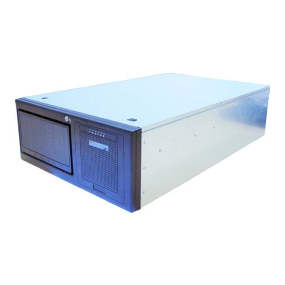
Chapter 1: Overview About the TYAN FT48-B7025 ® Congratulations on your purchase of the TYAN FT48-B7025, a highly optimized rack-mountable 4U barebone system. FT48-B7025 is designed ® to support dual Intel Nehalem-EP/Nehalem-WS 2S processors and up to 6 channels with 18 DDR3 DIMMs, providing a rich feature set and ®... -
Page 10: Product Models
Product Models Model HDD Bays Power supply (4) 3.5" Hot-Swap HDD ERP1U hot-swap / B7025F48W4H Bays; Extra (4) hot-swap (2+0) trays available for add-on (8) 3.5" Hot-Swap HDD ERP1U hot-swap / B7025F48W8HR Bays; (2+1) http://www.tyan.com... -
Page 11: Features
Features TYAN FT48-B7025 (B7025F48W4H / B7025F48W8HR (BTO)) Form Factor 4U Rack mount Chassis Model FT48 Dimension (H x W x D) 6.9" x 16.7" x 27.6" (176 x 425 x 700mm) System Motherboard S7025WAGM2NR-B Gross Weight 46.8 kg Buttons (1) RST / (1) ID / (1) PWR / (1) NMI... - Page 12 ACPI 2.0 power management BIOS Feature Power on mode after power recovery User-configurable H/W monitoring Auto-configurable of hard disk types Multiple boot options Operating OS supported list Please refer to our OS supported list. System FCC (DoC) Class A Regulation CE (DoC) http://www.tyan.com...
- Page 13 Operating Temp. 10° C ~ 35° C (50° F~ 95° F) Operating Non-operating Temp. - 40° C ~ 70° C (-40° F ~ 158° F) Environment In/Non-operating 90%, non-condensing at 35° C Humidity RoHS RoHS 6/6 Complaint http://www.tyan.com...
-
Page 14: Standard Parts List
Open the box carefully and ensure that all components are present and undamaged. The product should arrive packaged as illustrated below. 1.4.1 Box Contents Component Description 4U FT48 Chassis MAIN BOARD,S7025WAGM2NR-B 650W,PowerSupply, DeltaDPS-650JB B 120X120X38MM FAN,12V, 4800RPM, Delta 4-pin Front Panel board, Antrada http://www.tyan.com... - Page 15 SAS Backplane board, 4-port,Antrada PWR Backplane board (R02) FAN control board, Antrada http://www.tyan.com...
-
Page 16: Accessories
If any items are missing or appear damaged, contact your retailer or browse to TYAN’s website for service: http://www.tyan.com ® The web site also provides information of other TYAN products, as well as FAQs, compatibility lists, BIOS settings, etc. ®... -
Page 17: Optional Parts
HDD BP PWR CCBL-1094 CABLE, 2*2P, P4.2/B4P(F),P5.08/ Cable B4P(F),P5.08, L=550+50MM CABLE ASSY;HDD BP PWR DVD-ROM SATA CABLE,B4P(M), P4.2/B4P(F), CCBL-1095 PWR Cable P4.2/5P, P3.81/5P, P3.81/5P, P3.81, L=50/500+80+80MM CABLE ASSY;HDD BP PWR DVD-ROM B4P CABLE,B4P(M),P4.2/B4P(F),P4.2/ CCBL-1096 PWR Cable B4P(F),P4.2/B4P(F),P4.2/B4P(F), P4.2, L=50/500+80+80MM http://www.tyan.com... -
Page 18: About The Product
USB Ports Reset Button HDD LED Power Button Warning LED Power LED ID Button 1.6.2 System Rear View Thumb Screw Thumb Screw for MB Tray for top cover LAN1(L)/LAN2(R) USB Ports Expansion slots Power Supply VGA and COM Ports http://www.tyan.com... -
Page 19: Led Definitions
LED will show the system is identified with emitting blue light. Users from remote site could also activate ID LED by input a few commands in IPMI, detailed software support please visit http://www.tyan.com for lastest AST2050 user guide. Rear I/O... - Page 20 Description Green 10Mb/100Mb/1000Mb linked RJ-45 Linkage/ Blinking Green 10Mb/100Mb/1000Mb activity Activity(left) No LAN linked Amber 1000Mb linked/activity RJ-45 Linkage/ Green 100Mb linked/activity Activity(Right) 10Mb mode or No LAN linked NOTE: “Left” and “Right” are viewed from the rear panel. http://www.tyan.com...
-
Page 21: Motherboard (S7025) Layout
1.6.4 Motherboard (S7025) Layout The diagram is representative of the latest board revision available at the time of publishing. The board you receive may not look exactly like the above diagram. http://www.tyan.com... -
Page 22: Jumpers & Connectors
IPMB J47/J48 Rear Fan Audio Header SATA SGPIO Chassis Intrusion Header J167 SSI Fan Header J168 SPDIF Header J169 CD IN Clear CMOS Jumper Legend OPEN - Jumper OFF Without jumper cover CLOSED - Jumper ON With jumper cover http://www.tyan.com... -
Page 23: System Block Diagram
1.6.6 System Block Diagram The diagram is representative of the latest board revision available at the time of publishing. The board you receive may not look exactly like the above diagram. http://www.tyan.com... -
Page 24: Internal View
(Pre-installed) ② M1018 Front Panel Board and (3) 5.25 inch media bays System Fan Module ③ (3) 12038 hot-swap fan as pre-installed ④ System Main Board (8) Expansion slots ⑤ Mechanically support up to (4) full sized GPU card http://www.tyan.com... -
Page 25: Chapter 2: Setting Up
Most of the electrical and mechanical connections can be disconne- -cted with your hands. It is recommended that you do not use pliers to remove connectors as it may damage the soft metal or plastic parts of the connectors. http://www.tyan.com... -
Page 26: Precautions
Metallic parts or metal flakes can cause electrical shorts. Note: All connectors are keyed to only attach one way. All use the correct screw size as indicated in the procedures. http://www.tyan.com... -
Page 27: Installing Motherboard Components
Removing the Chassis Cover Follow these instructions to remove FT48-B7025 chassis cover. Press the button on the front top cover and slide the cover off. Unscrew the thumb screw securing the rear cover then slide the rear top cover off. http://www.tyan.com... -
Page 28: Installing The Cpu And Heatsink
Installing the CPU and Heatsink Follow the steps below on installing CPUs and CPU heatsinks. 1. Locate the CPU socket. 2. Press the lever and unlock the CPU socket. Lift protection up and lay the into socket(A), ensuring pin1 is correctly located(B); http://www.tyan.com... - Page 29 4. Close the socket cover and press the CPU lever down to secure the CPU; 5. Place the heatsink on top of the CPU and secure it with 8 screws. http://www.tyan.com...
-
Page 30: Installing The Memory
Press the memory slot locking levers in the direction of the arrows as shown in the following illustration. Align the memory module with the slot. When inserted properly, the memory slot locking levers lock automatically onto the indentations at the ends of the module. http://www.tyan.com... - Page 31 2). Refer to the memory population option table for recommended memory installation instruction. Memory Population Option Table ® To achieve the best performance, TYAN strongly recommended memory installation configuration as listed below: 1. Single CPU installed (CPU0 Only) Quantity of memory DIMM Slot √...
- Page 32 1). “√”indicates a populated DIMM slot. 2). If installing only one processor, you can choose either CPU0 or CPU1. 3). For two slots per channel configuration, it requires population to start with the DIMM slots furthest away from the processor. http://www.tyan.com...
-
Page 33: Installing The Pci-E Cards
1. Locate the expansion slot on the motherboard, unscrew the bracket from the slot you want to use. 2. Take the brackets out from the slot, insert the card into the slot and secure it with the screws you removed from the bracket. http://www.tyan.com... - Page 34 3. Connect the cables between the expansion card and the power distribution board, the connectors you use should match with the slot you add the card with. http://www.tyan.com...
-
Page 35: Installing Hard Drives
The FT48-B7025 supports up to eight 3.5” hard drives. Follow these instructions to install a hard drive. Press the locking lever latch and pull the locking lever open. Slide the HDD tray out. Place a hard drive into the HDD tray. http://www.tyan.com... - Page 36 Turn over the HDD unit and secure the HDD using 4 HDD screws. 5. Reinsert the HDD tray into the chassis and press the locking lever to secure the tray. http://www.tyan.com...
-
Page 37: Rack Mounting
Maintenance can be performed on the unit while in a rack but it is preferable to install the device in a fully operational condition. Screw Sack Including: A: Bracket for M6 screw--10 pcs B: M 6--10 pcs C: M 4-L5--16 pcs http://www.tyan.com... - Page 38 Installing the Outer Rails to the Unit Step1: Adjust the outer rails to fit the length of the rack. The sliding brackets have long slits to allow them to be fixed to the other part of the rails in various positions. http://www.tyan.com...
- Page 39 Secure the mounting brackets from outside, not inside, of the rack. Rack Mounting the Server Step1: Draw out the middle rail to the latch position. Step2: Lift the unit and then insert the inner slide rails into the middle rails. http://www.tyan.com...
- Page 40 Step3: Press the latch key and push the whole system in. Step4: Secure the mounting ears of the unit to the rack using two small brackets (A) and M6 screws (B). http://www.tyan.com...
-
Page 41: Opening The Chassis Front Bezel
Opening the Chassis Front Bezel 1. Insert the front bezel key (packed in a bag in the accessory box) and rotate the key 90 degrees counterclockwise to unlock the front bezel. 2. Open the front bezel. http://www.tyan.com... - Page 42 http://www.tyan.com...
-
Page 43: Chapter 3: Replacing Pre-Installed Components
Disassembly Flowchart The following flowchart outlines the disassembly procedure. Chassis cover System Fan Module and M1014 Fan Board HDD and M1216-P HDD Backplane M1018 Front Panel Board Heatsink/CPU/Memory/Add on cards MB Tray and MB M7025 PDB and Power Supply http://www.tyan.com... -
Page 44: Removing The Cover
Follow these instructions to replace the cooling fans in your system. Refer to Chapter 1.6.7 “internal view” and locate the cooling fans in your system. Unplug the installed single system fans in the fan module. Unscrew the fan holder and lift it up from the chassis. http://www.tyan.com... - Page 45 Unplug the cables connected to the fan board and turn over the fan holder. 5. Renew the fan board if it is necessary and assemble the fan module back follow the steps above in reverse. http://www.tyan.com...
-
Page 46: M1014 Fan Board Features
3.4.1 M1014 Fan Board Features FAN2 Connector FAN1 Connector FAN3 Connector FAN4 Connector FAN6 Connector FAN5 Connector http://www.tyan.com... -
Page 47: M1014 Fan Board Connector Pin Definition
FAN 1~FAN6: 4 pin Fan connector Definition Definition VDD+12V CLOCK J1/J2: Big 4 pin Power connector Definition Definition VDD+12V VCC+5V J3: PWM connector Definition Definition FAN1 PWM FAN1 PWM FAN1 PWM FAN1 PWM FAN1 PWM FAN1 PWM FAN PWM MUTE+ http://www.tyan.com... -
Page 48: Replacing M1216-P Sata/Sas Backplane
Remove the HDD trays corresponding to the SAS/SATA backplane to be replaced from the FT48-B7025. Disconnect all cables from the to be replaced and M1216-P remove the screw securing it. Renew the backplane and secure it following the steps above in reverse. http://www.tyan.com... -
Page 49: M1216-P Sata/Sas Backplane Features
M1216-P SATA/SAS Backplane Features Front view: Right to Left : J1/J2/J3/J4 29 Pin SAS Connector Rear view: Right to Left: J13/J14 Big 4 pin Power Connector Right to Left: J7/J5/J3/J1 Primary port connector Right to Left: J8/J6/J4/J2 Secondary port connector (SAS Only) http://www.tyan.com... -
Page 50: 3.5.2 M1216-P Connector Pin Definition
Replacing the Front Panel Control Board Follow these instructions to replace the M1018 LED control board. Disconnect the power cable and data cable from M1018. Push aside the latch and slide the LED control board unit out of the chassis. http://www.tyan.com... - Page 51 Remove three screws securing the LED control board to the bracket. 4. Lift the LED control board free from the chassis. After replacem- -ent, insert the unit into the chassis following the above proced- -ures in reverse. http://www.tyan.com...
-
Page 52: M1018 Led Control Board Features
3.6.1 M1018 LED Control Board Features Power Switch Warning LED Reset Switch Power LED NMI Switch ID Switch ID LED USB 2 LAN2 LED USB 1 LAN1 LED 2x14 pin header HDD LED 2x5 pin USB header http://www.tyan.com... -
Page 53: M1018 Led Control Board Connector Pin Definition
HD_LED- RESET+ RESET- Power LED+ Power LED- WLED+ WLED- Reserved Reserved EXT INT Voltages V5SB Reserved Power SW+ Power SW- LAN1 LED+ LAN1 LED+ LAN2 LED+ LAN2 LED+ Reserved Reserved ID LED-IN+ ID LED-IN- ID SW+ ID SW- Reserved http://www.tyan.com... -
Page 54: Replacing Power Supply And M7025 Pdb
Press the green button on the power supply and slide it out. After replacement, insert the power supply into the chassis following the above procedures in reverse. 3.7.2 Replacing M7025 Power Distribution Board 1. Disconnect the cables on the motherboard. Power cables: http://www.tyan.com... - Page 55 SAS cable, front panel cable: 2. Thumb the screw securing the motherboard tray, pull down the bar. 3. Slide the motherboard tray out carefully. http://www.tyan.com...
- Page 56 4. Disconnect the cables on the PDB. 5. Locate the 12 screws on the PDB, then you can renew the board and fix it back follow the steps above in reverse. http://www.tyan.com...
-
Page 57: M7025 Power Distribution Board Features
3.7.3 M7025 Power Distribution Board Features J6: Power Supply Connector J5: Power Supply Connector J4: Power Supply Connector PW11 PW10 http://www.tyan.com... -
Page 58: M7025 Pdb Connector Pin Definition
PW5: 2×10 Pin Power Connector Definition Definition +12V +12V +12V +12V +12V +12V +12V +12V +12V +12V PW6/7: 2×4 Pin Power Connector Definition Definition +12V +12V +12V +12V PW8/9/10/11: 2×2 Pin Power Connector for Fan board / HDD backplane Definition Definition +12V http://www.tyan.com... - Page 59 Definition SMBCLK SMBDAT SMB_ALERT VDD3.3V Definition 5VSB RSVD Note: Connect pin1-pin2 for PSU 2+0 or 2+1; Connect pin2-pin3 for PSU 1+0 or 1+1; Default: connect pin1-pin2 for PSU 2+0 or 2+1. J10: Definition RSVD PSON_EN Default: Connect J10 pin1-pin2 http://www.tyan.com...
-
Page 60: Replacing S7025 System Board
Replacing S7025 System Board Followed Chapter 3.7.2 to set the mother board tray free. Unscrew the motherboard and carefully lift it up from the MB tray. Renew the board and fix it back follow the steps above in reverse. http://www.tyan.com... -
Page 61: Appendix I: Cable Connection Tables
S7025 MB Board → → Mini-SAS Cable → → 3. B4P PWR Cable for HDD BP SATA/SAS BP Board to Power Distribution Board (PDB) SATA/SAS BP Connect to Board → B4P PWR Cable PW10 → B4P PWR Cable PW11 http://www.tyan.com... - Page 62 B4P PWR Cable → B4P PWR Cable 6. PDB PWR Cables FDB board to Fan board FDB board Connect to S7025 MB → PSMI Cable 2X12P PWR → Cable 2X10P PWR → PW3,5,6 Cable → GPU PWR PW6,7 GPU Card http://www.tyan.com...
-
Page 63: Appendix Ii: Fru Parts Table
340746600023 Assy 650W,Power Supply, Delta Power Supply CPSU-0330 471015200198 DPS-650JB B 120X120X38MM CFAN-0180 336252012259 FAN,12V,4800RPM, Delta 4-pin HEATSINK;AL/CU,+PIPE,1366- Heat Sink & Cooler CHSK-0460 343790900002 3U-PASSIVE-HEATSINK M7025-PDB 411790900012 PWR Backplane board (R02) PCBA SAS Backplane board, 4-port, M1216-P 412758500002 Antrada http://www.tyan.com... - Page 64 CABLE ASSY;HDD BP PWR CABLE,B4P(M),P4.2/B4P(F),P4 CCBL-1096 422790©900012 .2/B4P(F),P4.2/B4P(F),P4.2/B4 P(F), P4.2, L=50/500+80+80MM PWR CORD; US,125V, CCBL-0310 332810000280 18AWGX3C,YONGCHIN PWR CORD;EU,250V, CCBL-0300 332810000281 H05VV-FX3C,10A,0.75MM Note: The table is subject to change without notice. Please visit our Web site at http://www.tyan.com for latest update. http://www.tyan.com...
-
Page 65: Appendix Iii: Technical Support
(which can have expensive consequences). If these options are not available for you then TYAN Computer Corporation can help. Besides designing innovative and quality products for over a decade, Tyan has continuously offered customers service beyond their expectations. - Page 66 Return Merchandise Authorization (RMA) number. The RMA number should be prominently displayed on the outside of the shipping carton and the package should be mailed prepaid. TYAN will pay to have the board shipped back to you ®...
Need help?
Do you have a question about the FT48 B7025 and is the answer not in the manual?
Questions and answers