Table of Contents
Advertisement
Quick Links
Advertisement
Table of Contents

Related Manuals for TYAN FT76-B7922


Summary of Contents for TYAN FT76-B7922
- Page 1 FT76-B7922 Service Engineer’s Manual...
- Page 2 TYAN products including liability or ® warranties relating to fitness for a particular purpose or merchantability. TYAN retains the right to make changes to produce descriptions and/or specifications at ® any time, without notice. In no event will TYAN...
- Page 3 Notice for Canada This Class A digital apparatus complies with Canadian ICES-003. Cet appareil numérique de la Classe A est conforme à la norme NMB-003 du Canada. Notice for Europe (CE Mark) ● http://www.tyan.com...
- Page 4 Replace only with the same or equivalent type recommended by manufacturer. Dispose of used battery according to manufacturer instructions and in accordance with your local regulations. VCCI-A ● この装置は、クラスA情報技術装置です。この装置を家庭環境で使用すると電波妨 害を引き起こすことがあります。この場合には使用者が適切な対策を講ずるよう要 求されることがあります。 Safety: EN/IEC 60950-1 ● This equipment is compliant with CB/LVD of Safety: EN/IEC 60950-1. http://www.tyan.com...
- Page 5 Chapter2: Setting Up This chapter Covers procedures on installing the CPU, memory modules, add on card and hard drives. Give an overview about the FT76-B7922 barebone from an overall angle. Chapter 3: Replacing the Pre-installed Components This chapter covers the removal and replacement procedures for pre-installed components.
- Page 6 Safety and Compliance Information Before installing and using TYAN FT76-B7922, take note of the following precautions: ·Read all instructions carefully. ·Do not place the unit on an unstable surface, cart, or stand. ·Do not block the slots and opening on the unit, which are provided for ventilation.
- Page 7 You must become familiar with the safety information in this guide before you install, operate, or service TYAN products. Symbols on Equipment Caution. This symbol indicates a potential hazard.
- Page 8 · Do not attempt to move a fully loaded rack. Remove equipment from the rack before moving it. · Do not attempt to move a rack on an incline that is greater than 10 degrees from the horizontal. http://www.tyan.com...
- Page 9 This will reduce the risk of personal injury, fire, or damage to the equipment. The total rack load should not exceed 80 percent of the branch circuit rating. Consult the electrical authority having jurisdiction over your facility wiring and installation requirements. http://www.tyan.com...
- Page 10 TYAN, your authorized TYAN partner, or their agents. Equipment Modifications · Do not make mechanical modifications to the system. TYAN is not responsible for the regulatory compliance of TYAN equipment that has been modified.
- Page 11 – The product has been dropped or damaged. – The product does not operate normally when you follow the operating instructions. Warning: This equipment is compliant with Class A of CISPR 32. In a residential environment this equipment may cause radio interference. http://www.tyan.com...
-
Page 12: Table Of Contents
Table of Contents Chapter 1: Overview ..............14 About the TYAN FT76-B7922..........14 Product SKUs ..............14 Features................15 Standard Parts List .............. 24 1.4.1 Box Contents ..............24 1.4.2 Accessories ..............24 About the Product ..............25 1.5.1 System Front View ............25 1.5.2... - Page 13 AMIBIOS Post Code (Aptio) ..........163 Appendix I: Fan and Temp Sensors .......... 173 Appendix II: Cable Connection Tables ........180 Appendix III: FRU Parts Table ............ 182 Appendix IV: Glossary ..............183 Appendix V: Technical Support ..........189 http://www.tyan.com...
-
Page 14: Chapter 1: Overview
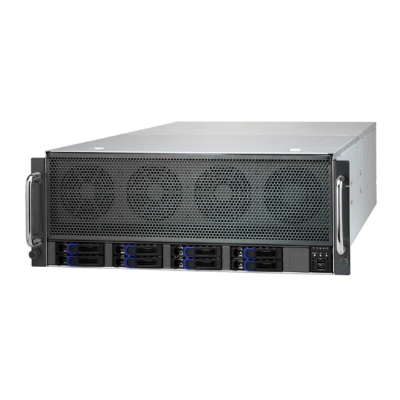
IT environment but also offers a smooth path for future application usage. ® also offers the FT76-B7922 in a version that can support up to eight 2.5” TYAN hot-swap SATAIII HDDs.FT76-B7922 uses rack-mountable 4U chassis featuring a robust structure and a solid mechanical enclosure. All of this provides FT76-B7922 the power and flexibility to meet the needs of nearly any server application. -
Page 15: Features
Features TYAN FT76B7922 (B7922F76U8HR-4T-HE-X) Form Factor 4U Rackmount Gross Weight 41.3 kg System Chassis Model FT76 Dimension (D x W x H) 29.92" x 17.17" x 6.93" (760 x 436 x 176mm) Motherboard S7922GM2NR-2T Buttons (1) PWR / (1) RST / (1) ID... - Page 16 Double-width) + (1) PCI-E Gen3 x8 slot (Full-height, 10.5" length) (1) M7922F76-HSP riser card for (2) Hot-swap Pre-install TYAN Riser PCI-E Gen3 x8 slots / (1) M7922F76-IO-HE riser Card card for (2) PCI-E Gen3 x8 slots + (1) PCI-E Gen2 x8 slot + (4)PCI-E Gen3 x16 slots 1) P3250USR-8I storage mezz.
- Page 17 Environment Humidity Recommend to fully populate 4x GPU/coprocessor Note modules for best thermal performance RoHS RoHS 6/6 Compliant (1) FT76-B7922 w/Intel Xeon Phi-aware FW Barebone Barebone Manual (1) Web User's manual / (1) Quick Installation Guide Package Contains Installation CD...
- Page 18 TYAN FT76B7922 (B7922F76U8HR-4T) Form Factor 4U Rackmount Gross Weight 41.3 kg System Chassis Model FT76 Dimension (D x W x H) 29.92" x 17.17" x 6.93" (760 x 436 x 176mm) Motherboard S7922GM2NR-2T Buttons (1) PWR / (1) RST / (1) ID...
- Page 19 (2) LAN mezz. slots + (9) PCI-E Gen3 x8 slots (1) P3250USR-8I storage mezz. card w/ (8) SAS Pre-install TYAN Mezz 12G ports / (1) P1210C-2T LAN mezz. card w/ (2) Card 10GbE ports Port Q'ty (1) PHY / (4) 10GbE ports...
- Page 20 Intel Xeon E7-8800 v3 series processors can be Note supported with limited thermal condition RoHS RoHS 6/6 Compliant Barebone (1) FT76-B7922 Barebone Manual (1) Web User's manual / (1) Quick Installation Guide Package Installation CD (1) TYAN installation CD Contains...
- Page 21 TYAN FT76B7922 (B7922F76U8HR-2T) Form Factor 4U Rackmount Gross Weight 41.3 kg System Chassis Model FT76 Dimension (D x W x H) 29.92" x 17.17" x 6.93" (760 x 436 x 176mm) Motherboard S7922GM2NR-2T Buttons (1) PWR / (1) RST / (1) ID...
- Page 22 (2) LAN mezz. slots + (9) PCI-E Gen3 x8 slots Pre-install TYAN Mezz (1) P3250USR-8I storage mezz. card w/ (8) SAS Card 12G ports Port Q'ty (2) 10GbE ports / (1) PHY Controller Intel X540-AT2 Realtek RTL8211E Others (2) SATA DOM 3G...
- Page 23 Intel Xeon E7-8800 v3 series processors can be Note supported with limited thermal condition RoHS RoHS 6/6 Compliant Barebone (1) FT76-B7922 Barebone Manual (1) Web User's manual / (1) Quick Installation Guide Package Contains Installation CD (1) TYAN installation CD...
-
Page 24: Standard Parts List
Standard Parts List This section describes FT76-B7922 package contents and accessories. Open the box carefully and ensure that all components are present and undamaged. The product should arrive packaged as illustrated below. 1.4.1 Box Contents FT76-B7922 Chassis Kit (1) 4U chassis ... -
Page 25: About The Product
About the Product The following views show you the product. 1.5.1 System Front View http://www.tyan.com... - Page 26 Drive State Active LED(Green) Status LED(Orange) Without HDD Drive Present, No Active Solid On Drive Present, With Active Blinking Drive Failure Don’t care Solid On Raid Rebuild Don’t care Blinking @4 Hz Drive Locate Identify Don’t care Blinking @1 Hz http://www.tyan.com...
-
Page 27: System Rear View
(4) FH/10.5”L/DW PCI-E Gen.3 x16 slots for high-performance co-processor modules (2) FH/HL hot-swap PCI-E Gen.3 x8 slots UID Button LAN3/1000M (Dedicate IPMI) + (2) USB v2.0 LAN2/10Gbps+LAN1/10Gbps(from left to right) D-sub VGA + DB-9 COM1 (3+1) 4,800Wdc (@220Vac) RPSU 80+ Platinum http://www.tyan.com... -
Page 28: Led Definitions
(Link/Activity) (Speed) No Link Solid Green Solid Green Link 100 Mbps Blinking Green Solid Green Active Solid Green Solid Amber Link 1000 Mbps Blinking Green Solid Amber Active Solid Amber Solid Amber Link (10Gbps) Solid Amber Solid Amber Active http://www.tyan.com... - Page 29 (PMBus reading), or hot spot temperature>95deg (PMBus reading), high power, high current, slow fan(<1200rpm). AC present Only 12VSB on(PS off) Blink GREEN or PS in Smart Redundant state Output ON and OK AMBER AC cord unplugged http://www.tyan.com...
-
Page 30: Internal View
1.5.4 Internal View (4) 9238 Easy-swap System FANs (8) Memory Riser with (96) R-DDR4 DIMMs (4) CPU Socket R1 (HSW-EX) (2) Power Distribution Board http://www.tyan.com... -
Page 31: Chapter 2: Setting Up
Caution! To avoid damaging the motherboard and associated components, do not use torque force greater than 7kgf/cm (6.09 lb/in) on each mounting screw for motherboard installation. Do not apply power to the board if it has been damaged. http://www.tyan.com... -
Page 32: Precautions
Working on a system that is connected to a power supply can be extremely dangerous. Follow the guidelines below to avoid damage to FT76-B7922 or injury to yourself. Ground yourself properly before removing the top cover of the system. -
Page 33: 2.1 Installing Motherboard Components
2.1.1 Removing the Chassis Cover Follow these instructions to remove FT76-B7922 chassis cover. Remove one screw on the front side as illustrated in the image. Push the two gutters in the direction of the arrow to remove the top cover. - Page 34 Unscrew the top cover and release the latches to remove the top cover from Remove the 2 screws from the air duct. http://www.tyan.com...
-
Page 35: Installing The Cpu And Heat Sink
Installing the CPU and Heat sink Follow the steps below on installing CPUs and CPU heat sinks. Locate the CPU socket. Started at CPU0 and press the lever to unlock the CPU socket. Lift the CPU socket cover up. http://www.tyan.com... - Page 36 Take out the protection cover and place the CPU to the CPU socket; Close the socket cover. Close the socket levers. http://www.tyan.com...
- Page 37 Install the heatsink to the CPU0 socket. Connect the heatsink cable to the motherboard CPU0_FAN. http://www.tyan.com...
-
Page 38: Installing The Memory
2.1.3 Installing the Memory Before installing memory, ensure that the memory you have is compatible with the motherboard and processor. Check the TYAN Web site at http://www.tyan.com details of the type of memory recommended for your motherboard. Follow these instructions to install the memory modules onto the M7922F76-MR Memory Riser. - Page 39 3. Press the memory slot locking levers in the direction of the arrows as shown in the following illustration. 4. Align the memory module with the slot. When inserted properly, the memory slot locking levers lock automatically onto the indentations at the ends of the module. http://www.tyan.com...
- Page 40 3. Populate the same DIMM type in each channel, specifically - Use the same DIMM size - Use the same # of ranks per DIMM 4. Dual-rank DIMMs are recommended over single-rank DIMMs. http://www.tyan.com...
- Page 41 Intel Xeon processor HSW-EX 4S platform product families Support NOTE 1: 1DPC => One dimm per channel 2DPC => Two dimm per channel Physical Ranks are used to calculate DIMM Capacity. Supported DRAM Densities are 4Gb, 8Gb. http://www.tyan.com...
-
Page 42: Installing Expansion Cards
M7922F76-IO) PCI-E Gen.2 x8 w/ tailored pin-outs dedicated for TYAN dual port 10GbE networking adapter (sourced from CPU#1) (J23/J33) PCI-E Gen.3 x8 w/ tailored pin-outs dedicated for TYAN SAS 12G RAID adapter (sourced from CPU#0)(J24/J34) ... - Page 43 2. Insert the card into the slot and secure it with the screws you removed from the bracket. Connect the cables between the expansion card and the power distribution board, the connectors you use should match with the slot you add the card with. http://www.tyan.com...
-
Page 44: Tyan ® Lan Card And Sas Raid Card
® 2.1.5 TYAN LAN card and SAS Raid Card ® P1210C-2T LAN Card (TYAN dual port 10Gbe networking adapter) ® P3250 USR-8I SAS Raid Card (TYAN SAS 12G RAID adapter) http://www.tyan.com... - Page 45 M7922F76-HSP Hot-Swappable PCI-E Riser card FT76-B7922 has two hot-swapped expansion slots which can support LAN card, storage card, etc. Follow these instructions to install expansion cards. 1. Press the tab to pull out the hot-swapped PCIE riser bracket. Release the screw on the PCIE dummy bracket and open the iron bar to remove the PCIE cover shield.
- Page 46 Insert the PCI-E card in the direction of arrows as shown. Secure the riser card bracket to the chassis with one screw. http://www.tyan.com...
-
Page 47: Installing Hard Drives
2.1.6 Installing Hard Drives The FT76-B7922 supports eight 2.5” Hard Drives. Follow these instructions to install a hard drive. Located at the 2.5” HDD tray on the chassis. Press Locking lever to release the 2.5” HDD tray. Pull the 2.5” HDD tray out of the chassis. - Page 48 5. Place a hard drive into the drive tray. Use four screws to secure the HDD. 6. Reinsert the HDD tray into the chassis. Press the locking lever to secure the hard drive. Repeat the same procedures to install other HDD trays. http://www.tyan.com...
-
Page 49: Rack Mounting
Mounting Ears screw Pack x 1 2.2.1 Installing the Server in a Rack Follow these instructions to mount the TYAN FT76-B7922 into an industry standard 19" rack. NOTE: Before mounting the TYAN FT76-B7922 in a rack, ensure that all internal components have been installed and that the unit has been fully tested. - Page 50 Installing the Inner Rails to the Chassis 1. Screw the mounting ears to each side of the FT76-B7922 as shown using six screws from the supplied mounting ears screw pack. 2. Draw out the inner rail from the rail assembly. When the rail comes to a stop, pull the tab to release the latch and completely draw the inner rail out.
- Page 51 Installing the Outer Rails to the Unit Secure the outer rails to the rack using four M5 screws (A) and fixed iron (B) on each side. Rack Mounting the Server Lift the unit and then insert the inner slide rails into the Outer rails. http://www.tyan.com...
- Page 52 Secure the two rotary screws on the mounting ears of the unit to the rack. http://www.tyan.com...
-
Page 53: Chapter 3: Replacing Pre-Installed Components
Fan Board, M7922F76-IO PCI-E Riser Board, M1268F76-BP12-8 HDD Backplane Board, M7922F76-MPB Memory Riser Power Board, M7922F76-PDB Power Distribution Board, M7922F76-HSP Hot-Swappable PCI-E Riser card, System Fan and Power Supply, etc. Disassembly Flowchart The following flowchart outlines the disassembly procedure. http://www.tyan.com... -
Page 54: Removing The Cover
Removing the Cover Before replacing any parts you must remove the chassis cover. Follow Chapter 2.1.1 to remove the cover of FT76-B7922. Replacing the Power Supply To replace the power supply follow these instructions. Press the tab as shown in the diagram and pull out the power. -
Page 55: Replacing Hdd Backplane Board
Replacing HDD Backplane Board Follow these instructions to replace the M1268F76-BP12-8 HDD Backplane Board. Disconnect all the HDD backplane cables. Remove the 2 screws secure the chassis on the both sides. Removing the one screw on the other side. http://www.tyan.com... - Page 56 Lift up the HDD bracket from the chassis. 5. Unscrew the HDD BP Board and remove the BP mylar. http://www.tyan.com...
-
Page 57: Hdd Back Plane Board Features
3.5.1 HDD Back Plane Board Features (8) SAS Output Connector Integrated I/O (2) Mini SAS HD Connector (1 ) Power Connector (1 ) CPLD JTAG Connector W34.1*L381mm Board size http://www.tyan.com... -
Page 58: Hdd Backplane Board Pin Definition
3.5.2 HDD Backplane Board Pin Definition Power 1: 2 x 4 Pin Power connector Definition Definition +12V +12V +12V +12V J9: JTAG Connector Signal Signal JTAG_TCK JTAG_TDO VCC3_3 JTAG_TMS JTAG_TDI http://www.tyan.com... -
Page 59: Replacing The System Fan
Replacing the System Fan 1. Lift the fan which you need to replace up. 2. Unscrew to detach the system fan to replace a new fan. 3. Unscrew both sides to detach the system fan. http://www.tyan.com... - Page 60 4. Push the latch in the direction as the arrow shown to release the fan from the iron holder. 5. Remove the iron holder to replace a new fan. http://www.tyan.com...
- Page 61 6. After replacing a new one, put the fan unit back into the cage. http://www.tyan.com...
-
Page 62: Replacing The System Fan Board
Follow these instructions to replace the Fan Backplane Board in your system. Remove the 4 screws from the chassis. Remove the 3 screws from the chassis. 3. Lift the system bracket beside the Fan cage from the chassis. http://www.tyan.com... - Page 63 4. Disconnect all the cables from the M1810F76-FB fan board. Remove the 4 screws from the chassis. 6. Lift the Fan cage from the chassis. http://www.tyan.com...
- Page 64 7. Take out the Fan cage and turn it over to remove the 4 screws. 8. Renew the board and tighten the screw place it back to the chassis following the above procedures in reverse. http://www.tyan.com...
-
Page 65: Fan Board Features
(1) FAN Cable Connector 3.6.3 Fan Board Pin Definition Power Connector: 2x4-pin Power Connector Definition Definition +12V +12V +12V +12V J8: 2×10-Pin System Fan Connector for Motherboard Definition Definition Tachometer Input1 PWM Output2 PWM Output1 SMB Data SMB Clock P3V3_AUX PWM Output3 http://www.tyan.com... -
Page 66: Replacing Power Distribution Board
3. Lift the Power Distribution board from the chassis on both sides and remove the 4 screws to detach the PDB board. 4. Follow the steps described earlier in reverse order to reinstall the power distribution board into the chassis. http://www.tyan.com... -
Page 67: Power Distribution Board Pin Definition
J2: 2×4-Pin ATX Power Connector for FAN Board, the max current is 30A Signal Signal +12V +12V +12V +12V J3 ~ J18: 2×4-Pin ATX Power Connector for GPU, the max current is 20A Signal Signal +12V +12V +12V +12V http://www.tyan.com... -
Page 68: Replacing The Riser Card
Replacing the Riser Card Follow these instructions to replace the M7922F76-HSP Riser Card. 1. Press the tab to pull out the hot-swapped PCIE riser bracket. 2. Unscrew the riser card from the bracket. http://www.tyan.com... -
Page 69: M7922F76-Hsp Riser Card Feature
3.8.1 M7922F76-HSP Riser card Feature Board size W22*L137mm (1 ) PCIE X8 Connector Integrated I/O (1 ) HSP to MB Connector http://www.tyan.com... -
Page 70: Replacing The Front Panel Board
Replacing the Front Panel Board Follow these instructions to replace the M1706G62-FPB Front Panel Board. 1. Unscrew and disconnect both cables from the front panel board. 2. Unscrew to release the Front Panel tray. 3. Unscrew to take out the front panel board. http://www.tyan.com... - Page 71 4. Replace a new front panel board and screw it to the front panel tray. 5. Prepare a new one to replace. Follow the procedure described earlier in reverse order to reinsert the front panel board into the chassis. http://www.tyan.com...
-
Page 72: Front Panel Board Features
1 VCC_USB0 Power connect to 5V (for USB) 6 USB_P1_P USB_P1 + 2 VCC_USB1 Power connect to 5V (for USB) 7 GND Ground 3 USB_P0_N USB_P0 - 8 GND Ground 4 USB_P1_N USB_P1 - 9 NC 5 USB_P0_P USB_P0 + 10 NC http://www.tyan.com... -
Page 73: Replacing The Mpb
After removing all of the Memory Risers, follow these instructions to remove the M7922F76-MPB from the Memory Riser. Turn over the MR to remove the 4 screws to release the MPB. 3.10.1 Memory Riser Power Board Feature Board size W63.5*L153.9mm Integrated I/O MPB to MR Connector http://www.tyan.com... -
Page 74: Replacing The Motherboard
After removing all of the aforementioned cables, follow these instructions to remove the motherboard from the chassis. Step1: detach the IO board 2. Before detach the board, the hot-swapped riser bracket must be take off. 3. Unscrew the power distribution board bracket. There are totally nine screws. http://www.tyan.com... - Page 75 4. Disconnect all cables from the IO board. 5. According to the screw location picture below to unscrew to lift up the IO board. IO board screw location (Total 10 screws) http://www.tyan.com...
- Page 76 Step2: detach the 3 Link bar Unscrew the back link bar. Lift up the back Link bar as illustrated. 3. Unscrew the middle link bar as illustrated. 4. Lift up the middle link bar as illustrated. http://www.tyan.com...
- Page 77 5. Remove the 4 screws from the chassis. 6. Remove the 3 screws from the chassis. 7. Lift the front link bar beside the Fan cage from the chassis. http://www.tyan.com...
- Page 78 8. According to the screw location picture to unscrew to replace a new motherboard as illustrated. Motherboard screw location (Total 12 screws) http://www.tyan.com...
-
Page 79: Chapter 4: Motherboard Information
Caution! To avoid damaging the motherboard and associated components, do not use torque force greater than 7kgf/cm (6.09 lb/in) on each mounting screw for motherboard installation. Do not apply power to the board if it has been damaged. http://www.tyan.com... -
Page 80: Board Image
Board Image S7922GM2NR-2T Motherboard S7922 This picture is representative of the latest board revision available at the time of publishing. The board you receive may not look exactly like the above picture. http://www.tyan.com... - Page 81 M7922F76-IO PCI-E Riser Board (x8) M7922F76-IO-HE PCI-E Riser Board (x16) http://www.tyan.com...
- Page 82 M7922F76-MR Memory Riser Board This picture is representative of the latest board revision available at the time of publishing. The board you receive may not look exactly like the above picture. http://www.tyan.com...
-
Page 83: Block Diagram
Block Diagram S7922 Block Diagram http://www.tyan.com... - Page 84 M7922F76-IO Board Block Diagram http://www.tyan.com...
-
Page 85: Mainboard Mechanical Drawing
Mainboard Mechanical Drawing http://www.tyan.com... -
Page 86: Board Parts, Jumpers And Connectors
Board Parts, Jumpers and Connectors S7922GM2NR-2T Motherboard http://www.tyan.com... - Page 87 Hook2 Select Jumper(J38) XDP Jumper(J21) XDP Jumper(J22) XDP Jumper(J23) MEMORY riser Power Slot CPU3_MR1_Power( J43) CPU3_MR0_Power(J46) CPU2_MR1_Power(J48) CPU2_MR0_Power(J50) CPU1_MR1_Power(J52) CPU1_MR0_Power(J54) CPU0_MR1_Power(J56) CPU0_MR0_Power(J58) MEMORY riser Slot CPU0_MR0 Slot(J57) CPU0_MR1 Slot(J55) CPU1_MR0 Slot(J53) CPU1_MR1 Slot(J51) CPU2_MR0 Slot(J49) CPU2_MR1 Slot(J47) CPU3_MR0 Slot(J45) CPU3_MR1 Slot(J43) http://www.tyan.com...
- Page 88 This diagram is representative of the latest board revision available at the time of publishing. The board you receive may not look exactly like the above diagram. For the latest board revision, please visit our web site at http://www.tyan.com. http://www.tyan.com...
- Page 89 I/O Board Jumpers&Connectors Jumper/Connector ID LED Button Header TYAN Module Header (J44) (SW1,J46) ID LED XDP Connector (J66) COM2 Header (J8) 4 Pin CPU Fan Connector(J80) HP#2 Button (J5) 4 Pin CPU Fan Connector(J79) HP#1 Button (J4) IPMB Connector (J65)
- Page 90 PCIe SLOTS PCI-E Gen.3 x8 w/ tailored pin-outs dedicated for TYAN SAS 12G RAID adapter (sourced from CPU#0,J23,J33) PCI-E Gen.2 x8 w/ tailored pin-outs dedicated for TYAN dual port 10GbE networking adapter (sourced from CPU#1,J24,J34) PCI-E Gen.3 x8 slot (sourced from CPU#1,J22) PCI-E Gen.3 x16 slots (for NV GPU &...
- Page 91 HDDLED- FAULT_LED-2 PWR_SW# LAN1_ACTLE+ LAN1_ACTLED- RST_SW# SMBCLK FP_IDLED_BTN_N INTRUSION# FPIO_TEMP_IN LAN2_ACTLED+ NMI_SW# J8: COM2 Header Signal Signal SOUT J50/J52/J58/J49: USB Front Panel Header (blue) Signal Signal USBD- USBD- USBD+ USBD+ J42: Vertical (Type A) USB Connectors Signal DATA2- DATA2+ http://www.tyan.com...
- Page 92 J65: IPMB Connector Signal Signal BMC_SMB_DATA BMC_SMB_CLK J44: TYAN Module Header Signal Signal P3V3 FRAME_N LAD0 LAD1 PLT_RST_N LAD2 LAD3 CLK_33M DBG_SERIRQ DBG_PRES_N VCC3_AUX TPM_ADDR_MB PCH_TPM_PP_EN J56: Chassis Intrusion Header Signal INTRUSION# Open Open: Use this header to trigger the system chassis intrusion alarm.
- Page 93 Connects to the Serial ATA ready drives via the Serial ATA cable. J41: SATA2.0 Connector(Black) Connects to the Serial ATA ready drives via the Serial ATA cable. PW1/2: SSI 8-pin System Power Connector Signal Signal VCC12 VCC12 VCC12 VCC12 http://www.tyan.com...
- Page 94 Description Blue System identified System not identified NOTE: The ID LED can be activated remotely using IPMI. Please visit the TYAN Web Site at http://www.tyan.com to download the latest IPMI Configuration Guide for more details. J6/J7/J15J20/J30/J35: Power Connector Signal Signal...
- Page 95 Short (Default) J38: Hook2 Select Jumper Signal Signal Open Pin 1-2 Closed: EAR_N=Hook2 ; PWR_DBG=Disable Open: EAR_N=Disable(1); PWR_DBG=HOOK2 Short (Default) J21/J22/J23: XDP Jumper PWRGD_LVC3_ Signal CPU1/2/3_PWR FM_ME_RCVR_N GOOD_BUF Pin 1-2 Closed: CPU2PWRGOOD(J21)/ CPU3PWRGOOD(J22) CPU1PWRGOOD(J23) (Default) Pin 2-3 Closed: Disable P3 http://www.tyan.com...
- Page 96 Some chassis include plastic studs instead of metal. Although the plastic studs are usable, MiTAC recommends using metal studs with screws that will fasten the motherboard more securely in place. Below is a chart detailing what the most common motherboard studs look like and how they should be installed. http://www.tyan.com...
-
Page 97: Chapter 5: Bios Setup
Select the previous value/setting of the field <+> Select the next value/setting of the field <F8> Load Fail Safe default configuration values of the menu <F3> Load the Optimal default configuration values of the menu <F4> Save and exit <Enter> Execute command or select submenu http://www.tyan.com... - Page 98 BIOS menus are continually changing due to continual BIOS updates over the product lifespan of the motherboard. The BIOS menus provided are current as of the date when this manual was written. Please visit TYAN’s website at http://www.tyan.com for information on BIOS updates available for this specific motherboard.
-
Page 99: Main Menu
It displays BIOS related information. Memory Information This displays the total memory size. System Date Adjust the system date. MM (Months): DD (Days): YYYY (Years) System Time Adjust the system clock. HH (24 hours format): MM (Minutes): SS (Seconds) Access Level Read only. http://www.tyan.com... -
Page 100: Advanced Menu
Serial Port Console Redirection Serial Port Console Redirection PCI Subsystem Settings PCI, PCI-X and PCI Express Settings CSM Configuration CSM Configuration, Enable/Disable Option ROM execution setting,etc Info Report Configuration Info Report Settings Trusted Computing (optional function) Trusted Computing (TPM) settings. http://www.tyan.com... - Page 101 Disabled / Enabled Enable Hibernation Enables or disables System ability to Hibernate (OS/S4 Sleep State). This option may not be effective with some OS. Disabled / Enabled Lock Legacy Resourse Enables or disables Lock of Legacy Resourse Disabled / Enabled http://www.tyan.com...
- Page 102 5.3.2 Hardware Health Configuration Auto Fan Control Auto Fan Control help. Disabled / Enabled BMC Alert Beep BMC Alert Beep On/Off. On / Off http://www.tyan.com...
- Page 103 5.3.2.1 Sensor Data Register Monitoring When you enter the Sensor Data Register Monitoring submenu, you will see the following dialog window pop out. Please wait 8~10 seconds. NOTE 1: SDR can not be modified. Read only. http://www.tyan.com...
- Page 104 http://www.tyan.com...
- Page 105 http://www.tyan.com...
- Page 106 http://www.tyan.com...
- Page 107 Load Onboard LAN Port 1 OpRom Enable or disable Load Option ROM for LAN Devices. Enabled with iSCSI / Enabled with PXE / Disabled Load Onboard LAN Port 2 OpRom Enable or disable Load Option ROM for LAN Devices. Enabled with PXE / Disabled http://www.tyan.com...
- Page 108 5.3.4 S5 RTC Wake Setting http://www.tyan.com...
- Page 109 Serial Port for Out-Of-Band Management/Windows Emergency Services (EMS) Console Redirection Console redirection enable or disable. Disabled / Enabled Console Redirection Settings The settings specify how the host computer (which the user is using) will exchange data. Both computers should have the same or compatible settings. http://www.tyan.com...
- Page 110 Bits per Second Select serial port transmission speed. The speed must be matched on the other side. Long or noisy lines may require lower speeds. 38400 / 9600 / 19200 / 115200 / 57600 Data Bits 8 / 7 http://www.tyan.com...
- Page 111 VT100 / LINUX / XTERMR6 / SCO / ESCN / VT400 Redirection After BIOS POST The settings specify if bootloader is selected than Legacy console redirection is disabled before booting to Legacy OS. Default value is always enable means Legacy. Always Enabled / Bootloader http://www.tyan.com...
- Page 112 0 if the num of 1’s in the data bits is even. Odd: parity bit is 0 if the num of 1’s in the data bits is odd. Mark: parity bit is always 1. Space: parity bit is always 0. Mark and Space parity do not allow for error detection. None / Even / Odd / Mark / Space http://www.tyan.com...
- Page 113 VT100 / LINUX / XTERMR6 / SCO / ESCN / VT400 Redirection After BIOS POST The settings specify if bootloader is selected than Legacy console redirection is disabled before booting to Legacy OS. Default value is always enable means Legacy. Always Enable / Bootloader http://www.tyan.com...
- Page 114 5.3.5.3 Legacy Serial Redirection Settings Legacy Serial Redirection Port Select a COM port to display redirection of Legacy, OS and Legacy OPROM Messages COM1 / Disable http://www.tyan.com...
- Page 115 VT-UTF8 / VT100 / VT100+ / ANSI Bits per Second Select serial port transmission speed. The speed must be matched on the other side. Long or noisy lines may require lower speeds. 115200 / 9600 / 19200 / 38400 / 57600 http://www.tyan.com...
- Page 116 ‘stop’ signal can be sent to stop the data flow. Once the buffers are empty, a ‘start’ signal can be sent to restart the flow. Hardware flow control uses two wires to send start/stop signal. None / Hardware RTS/CTS Data Bits / Parity / Stop Bits Read only. http://www.tyan.com...
- Page 117 Enables or Disables 64bit capable Devices to be decoded in Above 4G Address Space(Only if System supports 64 bit PCI decoding). Enable / Disabled SR-IOV Support If system has SR-IOV capable PCIe Devices, this option Enables or Disables Single Root IO Virtualization Support. Enable / Disabled http://www.tyan.com...
- Page 118 Defines number of microseconds software will wait before polling ‘Link training’ bit in link status register. Value range from 10 to 10000 uS Unpopulated Links In order to save power software will disable unpopulated PCI Express Links, if this option set to ‘Disable Link’ Keep Link On / Disable Link http://www.tyan.com...
- Page 119 1MB Upon Request / Always Option ROM Messages Set display mode for Option ROM Force BIOS / Keep Current Boot option filter This option controls Legacy/UEFI ROMs priority UEFI and Legacy / Legacy only / UEFI only http://www.tyan.com...
- Page 120 Determines OpRom execution policy for devices other than network, storage, or video legacy / UEFI first 5.3.8 Info Report Configuration Post Report Post Report support Enabled/Disabled Enabled / Disable NOTE: If Post Report is set to Disabled, the Delay Time submenu will not appear. Info Error Message http://www.tyan.com...
- Page 121 Info Error Message support Enabled / Disabled Summary Screen Summary Screen support Enabled / Disabled http://www.tyan.com...
- Page 122 5.3.9 Trusted Computing Configuration Security Device Support Enables or Disables BIOS support for security device. O.S. will not show Security Device. TDG EFI protocol and INT1A interface will not be available. Enabled / Disabled http://www.tyan.com...
- Page 123 USB Mass Storage Driver Support Enable/Disable USB Mass Storage Driver Support Enabled / Disabled Port 60/64 Emulation Enables I/O port 60h/64h emulation support. This should be enabled for the complete USB keyboard legacy support for non-USB aware OSes. Enabled / Disabled http://www.tyan.com...
- Page 124 Maximum time the device will take before it properly reports itself to the Host Controller. AUTO uses default value: for a Root port it is 100 ms, for a Hub port the delay is taken from Hub descriptor. Auto / Manual http://www.tyan.com...
-
Page 125: Intel Rcsetup Menu
Intel RCSetup Menu Processor Configuration Processor Parameters. Advanced Power Management Configuration Advanced power management Parameters. QPI Configuration QPI Configuration Memory Configuration Memory Configuration Memory RAS Configuration Memory RAS Configuration I/O Configuration I/O Configuration PCH Configuration PCH Configuration http://www.tyan.com... - Page 126 Miscellaneous Configuration Miscellaneous Configuration Server ME Configuration Configure Server ME Technology Parameters Runtime Error Logging Press <Enter> to view or change the runtime error log configuration. 5.4.1 Processor Configuration http://www.tyan.com...
- Page 127 Option to clear MCA during boot No/Yes Execute Disable Bit XD can prevent certain classes of malicious buffer overflow attacks when combined with a supporting OS (Windows Server 2003 SP1, Windows XP SP2, SuSE Linux 9.2, RedHat Enterprise 3 Update 3). Enabled / Disabled http://www.tyan.com...
- Page 128 Enables the Vanderpool Technology, takes effect after reboot Enable / Disable Enable SMX Enables Safer Mode Extensions. Enable / Disabled BIST Selection Enables BIST take effect after reboot Enable / Disabled Extended APIC Enable/Disable Extended APIC Support Enable / Disabled http://www.tyan.com...
- Page 129 5.4.2 Advanced Power Management Configuration Power Technology Enable the power management features. Custom / Disabled / Energy Efficient NOTE: Power Technology must be set to Custom, the CPU C/P/T State Control submenu can be modified. http://www.tyan.com...
- Page 130 Enabled / Disable Turbo Mode Enable/Disable Turbo Mode. Enabled / Disable P-state coordination HW-All (hardware) coordination is recommended over SW_ALL and SW_ANY (software coordination). HW_ALL / SW_ALL / SW_ANY Single PCTL MSR_CR_MUSC_PWR_MGMT 0x1AA Bit[0]:single_PCTL_EN NO / Yes http://www.tyan.com...
- Page 131 C0/C1 state / C2 state / C6 (non Retention) state / C6 (Retention State) CPU C3 Report Enable/Disable CPU C3 (ACPI C2) report to OS. Enabled / Disabled CPU C6 Report Enable/Disable CPU C6 (ACPI C3) report to OS. Enabled / Disabled http://www.tyan.com...
- Page 132 5.4.2.3 CPU T State Control ACPI T-States Enable /Disable CPU throttling by OS. Throttling reduces power consumption. Enabled / Disabled http://www.tyan.com...
- Page 133 5.4.2.4 CPU Advanced PM Turning http://www.tyan.com...
- Page 134 BIOS / OS Energy Performance BIAS setting Set Energy performance BIAS which overrides OS setting. Performance / Balanced Performance / Balanced Power / Power Workload Configuration Optimization for the workload characterization. Balanced is recommended. Balanced / I/O sensitive http://www.tyan.com...
- Page 135 Enable /Disable long Term Power limit override. If this option is disabled, BIOS will program the deafuit values for Long Term Power Limit and Long Term Power Limit Time window. Enabled / Disabled Short Our Pur Limit En Enable/ Disable long short Duration Power Limit (aka Power Limit 2). Enabled / Disabled http://www.tyan.com...
- Page 136 Link L0p Enable: Disable, Enable, Auto (default) Enable/ Disabled Link L1 Enable Link L1 Enable: Disable, Enable, Auto (default) Enable / Disabled MMIOH Size PerIIO Select MMIOH Size Per I/O 0x8_00000000 (32GB) / 0x10_00000000(64GB) / 0x20_00000000(128GB) / 0x40_00000000(256GB) / 0x80_00000000(512GB) / 0x100_00000000(1024GB) http://www.tyan.com...
- Page 137 If enabled, when there is a PCI resource allocation failure, PCI resources request for each socket will be auto-adjusted based on detected PCI device resource requirement; if disabled, no auto-adjustment to PCI resources requests will happen. Enabled / Disabled http://www.tyan.com...
- Page 138 5.4.4 Memory Configuration VMSE Lockstep mode 2:1 Independent Channel Operation 1:1 sub-Channel Lockstep Operation 2:1 Mode / 1:1 Mode http://www.tyan.com...
- Page 139 5.4.4.1 Memory Topology Configuration http://www.tyan.com...
- Page 140 http://www.tyan.com...
- Page 141 http://www.tyan.com...
- Page 142 Enabled / Disabled Channel Interleaving Select Channel Interleaving setting Auto / 1-way Interleave / 2-way Interleave / 3-way Interleave / 4-way Interleave Rank Interleaving Select rank Interleaving setting Auto / 1-way Interleave / 2-way Interleave / 4-way Interleave / 8-way Interleave http://www.tyan.com...
- Page 143 5.4.6 I/O Configuration Submenu Read only http://www.tyan.com...
- Page 144 Intel® VT for Directed I/O Configuration Submenu ® Intel VT for directed I/O (VT-d) ® Enable/Disable Intel I/O Virtualization Technology for directed I/O (VT/d) by reporting the I/O device assignment to VMM through DMAR ACPI Tables Disable / Enabled http://www.tyan.com...
- Page 145 5.4.7 PCH Configuration Read Only http://www.tyan.com...
- Page 146 5.4.7.1 PCH Device Configuration PCH state after G3 Select S0/S5 for ACPI state after a G3 S0 / S5 / Last State http://www.tyan.com...
- Page 147 5.4.7.2 PCH SATA Configuration http://www.tyan.com...
- Page 148 Designates this port supports port multipler Disabled / Enabled Spin Up Device AHCI Supports Staggered Spin-up Disabled / Enabled SATA Thermal Throtting Sets ‘Tinactive’ timing value for Thermal Throttling feature of PCH’s SATA controller Hard Disk Drive / Solid State Drive / Auto http://www.tyan.com...
- Page 149 5.4.7.2.1 Software feature Mask Configuration LED Locate If enabled, indicate that the LED/SGPIO hardware is attached and ping to locate Feature is enabled on the OS Disabled / Enabled http://www.tyan.com...
- Page 150 5.4.8 Miscellaneous Configuration Active Video Select active video type Onboard Device / Offboard Device http://www.tyan.com...
-
Page 151: Server Me Configuration Management
Server ME configuration Management Read Only http://www.tyan.com... -
Page 152: Runtime Error Logging
Disabled / Enabled McBank Error InjectSupport Enable/Disable McBank Error Injection Support. Disabled / Enabled S/W Error Injection Support When Enables S/W Error Injection is supported by unlocking MSR 0x750. Disabled / Enabled http://www.tyan.com... - Page 153 5.6.1 Memory Error Enabling Configuration Memory corrected error enabling Enable/disable Memory corrected error Disabled / Enabled Share interrupt Select SMI/OMCI/ErrPin for spare interrupt SMI / CMCL / Error Pin http://www.tyan.com...
-
Page 154: Server Mgnt Configuration
OS Watchdog Timer If enabled, starts a BIOS timer which can only be shut off by Intel Management Software after the OS loads. Helps determine that the OS successfully loader or follows the OS Boot watchdog Timer policy. Disabled / Enabled http://www.tyan.com... - Page 155 5 minutes / 10 minutes / 15 minutes / 20 minutes OS Wtd Timer Policy Configure how the system should respond if the OS Boot watchdog Timer expires. Not available if OS Boot watchdog Timer is disabled. Do Nothing / Reset / Power Down / Power Cycle http://www.tyan.com...
- Page 156 Choose options for reactions to a full SEL. Do Nothing / Erase Immediately Log EFI Status Codes Disable the logging of EFI Status Codes or log only error code or only progress code or both. Both / Disabled / Error Code / Progress Code http://www.tyan.com...
- Page 157 BMC Network Configuration Configuration Address Source Select the configure LAN channel parameters statically or dynamically (by BIOS or BMC). Unspecified option will not modify any BMC network parameters during BIOS phase. Current Setting / Static / Dynamic-Obtained by BMC http://www.tyan.com...
-
Page 158: Security
Security Password Description Read only. Administrator Password Install or change the password. User Password Install or change the password. http://www.tyan.com... -
Page 159: Boot
Select the keyboard NumLock state. Off / On Quiet Boot Enable or disable Quiet Boot option. Disabled / Enabled Endless Boot Enable or disable Endless Boot. Disabled / Enabled Boot Option #1/Boot Option #2 Select the first boot device. Device Name / Disabled http://www.tyan.com... -
Page 160: Save & Exit
Discard Changes and Reset Reset system setup without saving any changes. Save Options Read only. Save Changes Save changes done so far to any of the setup options. Discard Changes Discard changes done so far to any of the setup options. http://www.tyan.com... - Page 161 Restore Defaults Restore/Load Default values for all the setup options. Save as User Defaults Save the changes done so far as User Defaults. Restore User Defaults Restore the User Defaults to all the setup options. http://www.tyan.com...
-
Page 162: Chapter 6: Diagnostics
BIOS flash failure, you must contact your dealer for a replacement BIOS. There are no exceptions. TYAN does not have a policy for replacing BIOS chips directly with end users. In no event will TYAN be held responsible for damages done by the end user. -
Page 163: Amibios Post Code (Aptio)
Description 0x00 Note used Progress Codes 0x01 Power on. Reset type detection (soft/hard). 0x02 AP initialization before microcode loading 0x03 North Bridge initialization before microcode loading 0x04 South Bridge initialization before microcode loading 0x05 OEM initialization before microcode loading http://www.tyan.com... - Page 164 Pre-memory CPU initialization (CPU module specific) 0x15 Pre-memory North Bridge initialization is started Pre-Memory North Bridge initialization (North Bridge module 0x16 specific) Pre-memory North Bridge initialization (North Bridge module 0x17 specific) Pre-Memory North Bridge initialization (North Bridge module 0x18 specific) http://www.tyan.com...
- Page 165 CPU post-memory initialization. System Management Mode 0x36 (SMM) initialization 0x37 Post-Memory North Bridge initialization is started. Post-Memory North Bridge initialization (North Bridge module 0x38 specific) Post-Memory North Bridge initialization (North Bridge module 0x39 specific) Post-Memory North Bridge initialization (North Bridge module 0x3A specific) http://www.tyan.com...
- Page 166 Reset PPI is not available. 0x5C – 0x5F Reserved for future AMI error codes S3 Resume Progress Codes S3 Resume is started (S3 Resume PPI is called by the DXE 0xE0 IPL). 0xE1 S3 Boot Script execution 0xE2 Video repost http://www.tyan.com...
- Page 167 Recovery capsule is not found. 0xFA Invalid recovery capsule 0xFB – 0xFF Reserved for future AMI error codes PEI Beep Codes # of Beeps Description Progress Codes Memory not installed Memory was installed twice (installPEIMemory routine in PEI Core called twice). Recovery started http://www.tyan.com...
- Page 168 North Bridge DXE initialization (North Bridge module specific) 0x6F North Bridge DXE initialization (North Bridge module specific) 0x70 South Bridge DXE initialization is started. 0x71 South Bridge DXE SMM initialization is started. 0x72 South Bridge devices initialization 0x73 South Bridge DXE initialization (South Bridge module http://www.tyan.com...
- Page 169 Console output devices connect 0x98 Console Input devices connect 0x99 Super IO initialization 0x9A USB initialization is started. 0x9B USB Reset 0x9C USB Detect 0x9D USB Enable 0x9E -0x9F Reserved for future AMI codes 0xA0 IDE initialization is started http://www.tyan.com...
- Page 170 PCI bus hot plug 0xB6 Clean-up of NVRAM 0xB7 Configuration Reset (reset of NVRAM settings) 0xB8 – 0xBF Reserved for future AMI codes 0xC0 – 0xCF OEM BDS initialization codes DXE Error Codes 0xD0 CPU initialization error 0xD1 North Bridge initialization error http://www.tyan.com...
- Page 171 Platform PCI resource requirements cannot be met. ACPI/ASL Checkpoints Status Code Description 0x01 System is entering S1 sleep state. 0x02 System is entering S2 sleep state. 0x03 System is entering S3 sleep state. 0x04 System is entering S4 sleep state. http://www.tyan.com...
- Page 172 System is waking up from the S3 sleep state. 0x40 System is waking up from the S4 sleep state. System has transitioned into ACPI mode. Interrupt controller 0xAC is in APIC mode. System has transitioned into ACPI mode. Interrupt controller 0xAA is in APIC mode. http://www.tyan.com...
-
Page 173: Appendix I: Fan And Temp Sensors
This section aims to help readers identify the locations of some specific FAN and Temp Sensors on the motherboard. A table of BIOS Temp sensor name explanation is also included for readers’ reference. IO Board NOTE: The red dot indicates the sensor. http://www.tyan.com... - Page 174 (rpm) Temp Sensor: PCH_Area_Temp(RT26),SYS_Air_Outlet(U96). They detect the system temperature around. NOTE: The system temperature is measured in a scale defined by Intel, not in Fahrenheit or Celsius. BIOS Temp Sensor Name Explanation: http://www.tyan.com...
- Page 175 http://www.tyan.com...
- Page 176 http://www.tyan.com...
- Page 177 http://www.tyan.com...
- Page 178 Temperature of Node5 DIMM B2 Slot Node6_DIMMC0 Temperature of Node6 DIMM C0 Slot Node6_DIMMC1 Temperature of Node6 DIMM C1 Slot Node6_DIMMC2 Temperature of Node6 DIMM C2 Slot Node7_DIMMD0 Temperature of Node7 DIMM D0 Slot Node7_DIMMD0 Temperature of Node7 DIMM D1 Slot http://www.tyan.com...
- Page 179 Fan speed of CPU_FAN_1 CPU1_FAN Fan speed of CPU_FAN_1 CPU2_FAN Fan speed of CPU_FAN_2 CPU3_FAN Fan speed of CPU_FAN_3 SYS_FAN_1 Fan speed of SYS_FAN_1 SYS_FAN_2 Fan speed of SYS_FAN_2 SYS_FAN_3 Fan speed of SYS_FAN_3 SYS_FAN_4 Fan speed of SYS_FAN_4 http://www.tyan.com...
-
Page 180: Appendix Ii: Cable Connection Tables
3. FP Ctrl and USB Cable Front Panel Board to M7922F76-IO Connect to IO BD → Control Cable → USB Cable 4. 2x4P FAN PWR Cable FAN BD to M7922F76-PDB FAN Board Connect to PDB-1 2x4P FAN → PWR1 PWR4 PWR Cable http://www.tyan.com... - Page 181 Connect to GPU Card 2X4P GPU → PWR1 (PDB1) GPU card PWR Cable-1 2X4P GPU → PWR2 (PDB1) GPU card PWR Cable-2 2X4P GPU → PWR1 (PDB2) GPU card PWR Cable-3 2X4P GPU → PWR2 (PDB2) GPU card PWR Cable-4 http://www.tyan.com...
-
Page 182: Appendix Iii: Fru Parts Table
Appendix III: FRU Parts Table FT76-B7922 FRU Parts Item Model Number Part Number Picture Description TF-POWER CORD;SBU,US,125 V,16 FRU-CS-0330 332810000514 AWG(1.31mm² ),1800mm,AC PWR CORD TF-POWER CORD;SBU,EU,250 V,16 FRU-CS-0460 332810000515 AWG(1.0mm² ),1800mm,AC PWR CORD POWER CABLE 2*4P(M),P4.2/2*4P(M),P4.2,L=150MM,Y CCBL-146X 422794300006 M490-B7012 GPU power cable SBU,20... -
Page 183: Appendix Iv: Glossary
CPU can manipulate data in a buffer before copying it to a disk drive. While this improves system performance (reading to or writing from a disk drive a single time is much faster than doing so repeatedly) there is the possibility of losing your data http://www.tyan.com... - Page 184 (like soundcards or keyboards) to access the main memory without involving the CPU. This frees up CPU resources for other tasks. As with IRQs, it is vital that you do not double up devices on a single line. Plug-n-Play devices will take care of this for you. http://www.tyan.com...
- Page 185 ROM chip which can, unlike normal ROM, be updated. This allows you to keep ® ’s up with changes in the BIOS programs without having to buy a new chip. TYAN BIOS updates can be found at http://www.tyan.com ESCD (Extended System Configuration Data): a format for storing information about Plug-n-Play devices in the system BIOS.
- Page 186 Plug-n-Play require you to reconfigure your system each time you add or change any part of your hardware. PXE (Preboot Execution Environment): one of four components that together make up the Wired for Management 2.0 baseline specification. PXE was http://www.tyan.com...
- Page 187 Sleep/Suspend mode: in this mode, all devices except the CPU shut down. SDRAM (Static RAM): unlike DRAM, this type of RAM does not need to be refreshed in order to prevent data loss. Thus, it is faster and more expensive. http://www.tyan.com...
- Page 188 CPUs without damaging the sensitive CPU pins. The CPU is lightly placed in an open ZIF socket, and a lever is pulled down. This shifts the processor over and down, guiding it into the board and locking it into place. http://www.tyan.com...
-
Page 189: Appendix V: Technical Support
TYAN serves multiple market segments with the industry's most competitive services to support them. "TYAN's tech support is some of the most impressive we've seen, with great response time and exceptional organization in general" - Anandtech.com ® You can contact TYAN Technical Support by using our Online Support System: http://12.230.196.231/helpstar/hsPages/login.aspx?ReturnUrl=%2fhelpstar%2fhsP... - Page 190 Return Merchandise Authorization (RMA) number. The RMA number should be prominently displayed on the outside of the shipping ® carton and the package should be mailed prepaid. TYAN will pay to have the board shipped back to you ®...
Need help?
Do you have a question about the FT76-B7922 and is the answer not in the manual?
Questions and answers